Abstract
Isotropic periodic sum (IPS) is a method to calculate long-range interactions based on the homogeneity of simulation systems. By using the isotropic periodic images of a local region to represent remote structures, long-range interactions become a function of the local conformation. This function is called the IPS potential; it folds long-ranged interactions into a short-ranged potential and can be calculated as efficiently as a cutoff method. It has been demonstrated that the IPS method produces consistent simulation results, including free energies, as the particle mesh Ewald (PME) method. By introducing the multipole homogeneous background approximation, this work derives multipole IPS potentials, abbreviated as IPSMm, with m being the maximum order of multipole interactions. To efficiently calculate the multipole interactions in Cartesian space, we propose a vector relation that calculates a multipole tensor as a dot product of a radial potential vector and a directional vector. Using model systems with charges, dipoles, and/or quadrupoles, with and without polarizability, we demonstrate that multipole interactions of order m can be described accurately with the multipole IPS potential of order 2 or m − 1, whichever is higher. Through simulations with the multipole IPS potentials, we examined energetic, structural, and dynamic properties of the model systems and demonstrated that the multipole IPS potentials produce very similar results as PME with a local region radius (cutoff distance) as small as 6 Å.
I. INTRODUCTION
Long-range interactions are crucial in governing properties of molecular systems. Because the calculation of long-range interactions is expensive, many methods have been developed for their efficient calculation. One main category is the cutoff based methods, such as the energy switch, energy shift, force switch, and force shift,1 as well as the “damped-shifted” potential2 and the force-matching functions.3 These methods are criticized for lack of physical basis4 and for having the undesirable effect of abrupt truncations.4,5 Another category is the field based methods which includes the reaction field6 and molecular field7 methods. These methods have a certain physical basis and have been successfully applied in some simulation studies.8–10
The third category is the image based methods, such as Ewald sum,11 Particle-mesh-Ewald (PME),12–18 and fast multipole algorithm (FMA).19,20 These methods avoid the deleterious effects of a cutoff and use the lattice images created by periodic boundary conditions (PBCs) to represent remote structures. In other words, remote structures are represented by the PBC images, so that the long-range interaction is a function of the coordinates of the atoms within the simulation box and the PBC parameters,
| (1) |
where ε(rij) is the pairwise interaction energy between atoms i and j, and N is the number of atoms in the simulation system. Because images generated by PBC depend not only on the atom positions but also on the PBC parameters, , the summation over images, ϕPBC(ri, rj, L), is a complicated function of ri, rj, and L and has to be calculated numerically with methods like PME and FMA. PBC images reside at lattice points and distribute discretely in space. As a result, the lattice sum of a pair of atoms depends not only on their distance but also on their relative orientation in the PBC box. Despite the drawbacks of the PBC image approximation, methods of this category have gained widespread acceptance due to efficient algorithms developed in recent decades.12–15,17–19,21–27
The isotropic periodic sum (IPS) method,28,29 like the lattice sum methods, is also an image based method. Instead of using the lattice images created by PBC, IPS uses the so-called isotropic periodic images to represent the remote structure. The isotropic periodic images distribute continuously in orientation. Because of this, the IPS interaction between a pair of atoms is independent of their relative orientation in the PBC box. Since the IPS images distribute in an isotropic and periodic way, the sum of interactions with IPS images is a function of distance for each pair of atoms within the local region and the radius of the local region, rc,
| (2) |
We call ϕIPS(rij, rc) the IPS potential, which is a function of distance of the interacting atom pair within the local region radius (or cutoff distance), rc. Unlike ϕPBC(ri, rj, L) which needs to be solved numerically, ϕIPS(rij, rc) depends only on the distance and can be solved analytically for most potential functions. For example, the interaction between a pair of point charges has the following analytical form, which is called the IPS electrostatic potential:28
| (3) |
where is the Euler’s constant and ψ(z) is the digamma function: , and . Here in Eq. (3) and in Secs. II–V, we drop the charges for convenience.
When the local region is comparable in size to the PBC box, the homogeneity approximation used by IPS is found to be no worse than the lattice approximation used by Ewald sum for non-lattice systems.28,30 The IPS method makes long-ranged nonbonded interactions short-ranged so that they can be calculated as simply as with a cutoff method. Therefore, the IPS method has the accuracy of lattice sum methods and can be calculated as efficiently as the cutoff methods. The primary benefit of using IPS versus PME is for speed and better parallelization, i.e., no k-space calculation, with comparable accuracy. Further, the IPS method is not limited to specific interaction types. The IPS potentials of many interaction types, such as electrostatic and Lennard-Jones energies, have been presented in our previous work.28 For homogeneous systems, the IPS method28 can be applied with a small local region, typically, rc = 10 Å. It has been demonstrated that the IPS results are fairly independent of the cutoff radius for homogeneous systems. For heterogeneous systems, the discrete fast Fourier transform accelerated 3D IPS (3D IPS/DFFT) method29 provides an efficient way to allow a local region large enough to contain the heterogeneity of a simulation system, for a more accurate calculation of long-ranged interactions. Venable and co-workers30 have compared 3D-IPS/DFFT with PME and demonstrated that this method is highly accurate for simple bulk fluids, liquid/liquid, and liquid/vapor interfaces, as well as lipid bilayers and monolayers. For lipid monolayers, 3D-IPS/DFFT is recommended over PME.30 Ojeda-May and Pu have extended the IPS method for quantum mechanical and molecular mechanical (QM/MM) simulation, demonstrating that the QM/MM-IPS method can be used as a reliable and efficient alternative to the QM/MM-Ewald method.31,32 IPS is more convenient than PME in decomposing pairwise interactions, which is essential for some new simulation methods, such as the virtual mixture of multiple states (VMMS’s) method.33 It has been demonstrated that the free energies calculated with the IPS method are consistent with that calculated with PME.33,34
While the IPS potentials of many interaction forms have been derived, multipole interactions have not yet been explored. It is recognized that multipoles have their advantages in describing molecular interactions.35–44 They are increasingly employed in force field development, such as the AMOEBA force field45,46 and the sticky water model.47 Even though multipole interactions decay faster than charge-charge interactions, the large number of multipole interaction components makes a reduction of interaction pairs highly desirable in simulation. Direct cutoff methods require a large cutoff distance to maintain a specific accuracy. For example, Bereau and co-workers43 applied the force-switch cutoff method in multipole interactions with a cutoff distance ranging from 12 Å for charge-dipole interactions to 9 Å for quadrupole-quadrupole interactions. Further reduction in cutoff distances would introduce significant errors in the calculation. PME can effectively reduce the number of interaction pairs by splitting interactions into direct sums and reciprocal sums. The interaction numbers in the direct sum can be significantly reduced with small cutoff distances.24 Therefore, much effort has been dedicated to implementing PME for the calculation of multipole-multipole interactions.18,24,27,48 However, the reciprocal sum has a significant additional cost and is a bottleneck for massive parallel computing. Therefore, deriving multipole IPS potentials is desirable for efficient simulation with multipole force fields. This work extends IPS electrostatic potential to multipole interactions by introducing the multipole background homogeneous approximation.
Multipole interactions can be calculated either in Cartesian space or in spherical harmonics basis. In Cartesian space, Sagui et al.24 utilized Challacombe’s efficient McMurchie-Davidson recursive scheme49,50 to enhance calculation efficiency, which scales with multipole order l as O(l4), whereas the spherical harmonic approach developed by Hattig51,52 scales as O(l3). Given the convenience of Cartesian expressions and the fact that the multipole IPS potentials no longer satisfy Laplace’s equation, we present the multipole IPS method in Cartesian space and leave the spherical harmonic expression to future work. To efficiently calculate multipole interactions, we present here a vector relation that calculates multipole tensors as dot products of a radial potential vector and directional vectors. This vector relation can be applied to any charge-charge potential forms, regardless of whether or not a potential form satisfies Laplace’s equation. Through several model systems of various polarities, we examine the behavior of the multipole IPS potentials of various orders and compare them with PME results.
II. METHOD AND ALGORITHM
A. A vector relation for the calculation of multipole interactions
With the IPS electrostatic potential shown in Eq. (3), charge-charge interactions are no longer based on the simple 1/r Coulomb potential form. We propose a way to calculate multipole interactions for any form of charge-charge potential. For a general type of interaction potential function, υ(r), potential V(R) is related to the charge distribution ρ(r) by the following relation:
| (4) |
Here, R is the position of any given point where the potential is being calculated, and r is the integration variable representing a charge position. υ(R − r) is the potential at R due to a unit charge at r, which can be expanded in Taylor series around r = 0 (|r| ≪ |R|),
| (5) |
The derivatives in each term of Eq. (5) depend only on the potential function and are called the generalized interaction tensors,
| (6) |
The electrostatic energy of a charge, q, at R, is the potential at its position multiplied by the charge, qV(R). In Secs. III–V, we drop the charge, i.e., use a unit charge, for convenience so that the potential function is the same as the energy function: υ(r) = ε(r). This generalized interaction tensor can be applied to any potential form, including the IPS potential shown in Eq. (3),
| (7) |
where t ≥ 0, u ≥ 0, and v ≥ 0 are the differential orders in x, y, and z directions, respectively. The electrostatic potential can be written as
| (8) |
where q, μα, θαβ, and oαβγ are charge, dipole, quadrupole, octopole, and hexadecapole, whose multipole orders are l = 0, 1, 2, and 3, respectively. The multipole moments of the charge distribution are defined as
| (9) |
Clearly, the multipole moments are independent of the interaction potential function form, υ(r). To be general, a multipole moment is denoted as Mtuv = ∫xtyuzvρ(r) dr, which has a multipole order of l = t + u + v. The interaction order between two multipoles, Mtuv and Mt′u′v′, is m = l + l′ = t + u + v + t′ + u′ + v′. Between two charge distributions, A and B, the multipole interaction energy is
| (10) |
Effective calculation of the tensors resides in the center of multipole interaction calculation. A series of recurrence relations have been developed for the calculation of multipole tensors. For example, McMurchie and Davidson developed the first recursion relation for Cartesian Gaussians.49 Challacombe et al. extended the McMurchie-Davidson formalism to the Cartesian multipole interaction tensors with a Coulomb type charge-charge interaction.50
Here, we propose a generalized multipole tensor calculation method for any type of charge-charge interaction. The generalized tensor can be factorized into a directional vector, atuv, and a radial potential vector, S, and conveniently expressed as the dot product of these two vectors,
| (11) |
The radial potential vector S = (S0, S1, S2, S3, S4, S5, …) is the same for all tensors and the directional vector is independent of the potential. The components of atuv and S can be calculated with the following direct and recursive relations:
| (12) |
| (13) |
Note that S0 = εele(r) can be any type of charge-charge interaction, e.g., εele(r) can be the standard Coulomb potential, the force-switched potential, the screened interaction in PME direct sum calculation, or the IPS potential shown in Eq. (3). The middle expression in Eq. (12) indicates that the components of S can be understood as the derivatives of the charge-charge potential function with respect to a variable, r2/2. The middle expression in Eq. (13) provides a polynomial form of the directional vectors. The polynomial constants, , , and , can be calculated with
| (13a) |
whose values for n = 0 ∼ 10 are listed in Table I. To illustrate the vector relation shown in Eqs. (11)–(13) for the calculation of multipole tensors, in Appendix A we list the expressions of S and atuv, as well as interaction energies for a multipole system with charges, dipoles, and quadrupoles.
TABLE I.
The polynomial constants, , for the directional vector calculation in Eq. (13).
| i | ||||||||||||
|---|---|---|---|---|---|---|---|---|---|---|---|---|
| 0 | 1 | 2 | 3 | 4 | 5 | 6 | 7 | 8 | 9 | 10 | ||
| n | 0 | 1 | 0 | 0 | 0 | 0 | 0 | 0 | 0 | 0 | 0 | 0 |
| 1 | 0 | 1 | 0 | 0 | 0 | 0 | 0 | 0 | 0 | 0 | 0 | |
| 2 | 0 | 1 | 1 | 0 | 0 | 0 | 0 | 0 | 0 | 0 | 0 | |
| 3 | 0 | 0 | 3 | 1 | 0 | 0 | 0 | 0 | 0 | 0 | 0 | |
| 4 | 0 | 0 | 3 | 6 | 1 | 0 | 0 | 0 | 0 | 0 | 0 | |
| 5 | 0 | 0 | 0 | 15 | 10 | 1 | 0 | 0 | 0 | 0 | 0 | |
| 6 | 0 | 0 | 0 | 15 | 45 | 15 | 1 | 0 | 0 | 0 | 0 | |
| 7 | 0 | 0 | 0 | 0 | 105 | 105 | 21 | 1 | 0 | 0 | 0 | |
| 8 | 0 | 0 | 0 | 0 | 105 | 420 | 210 | 28 | 1 | 0 | 0 | |
| 9 | 0 | 0 | 0 | 0 | 0 | 945 | 1260 | 378 | 36 | 1 | 0 | |
| 10 | 0 | 0 | 0 | 0 | 0 | 945 | 4725 | 3150 | 630 | 45 | 1 | |
B. Multipole IPS potentials
Multipoles are an alternative way to describe a group of point charges, and interactions between these point charges are the sum of interactions between these multipoles. The interaction between the point charges can be calculated by the IPS electrostatic potential28 as shown in Eq. (3). According to Eq. (12), the IPS electrostatic potential shown in Eq. (3) has non-zero radial potential vectors at the local region boundary (r = rc). Here, we introduce a multipole background homogeneous approximation that the background multipole IPS interactions have zero sums and can be removed from pairwise terms. That is, for any multipole, Mtuv, at interaction site i, we have
| (14) |
Here, is the background radial potential vector. Based on the recursive relation of S components, Eq. (12), the background radial potential vector components can be derived in the following way:
| (15) |
Here, m is the order of the background potential. According to the definition of the radial potential vector, Eq. (12), the background potential is . From Eq. (15) we can see that the background radial potential vector has the same components with i ≤ m + 1 as the IPS electrostatic radial potential vector at the boundary. By subtracting the background potential of order m from the IPS electrostatic potential, we obtain the multipole IPS potential of the mth order, which has zero derivatives of up to the (m + 1)th order. We abbreviate the multipole IPS potentials of order m as IPSMm, which can be expressed by the following recursive equation:
| (16) |
For convenience, we list the IPSMm potentials for m ≤ 5 in Appendix B.
It is easy to verify that the IPSMm potential has zero derivatives of up to the (m + 1)th order at the boundary,
| (17) |
which we call the IPS boundary condition for multipole interactions. Because the long-range part of the IPSMm potentials shown in Eq. (16) are all even functions, we fit the long-range part of the IPSMm potentials with rational even polynomial functions, for an easy implementation in molecular simulation,
| (18) |
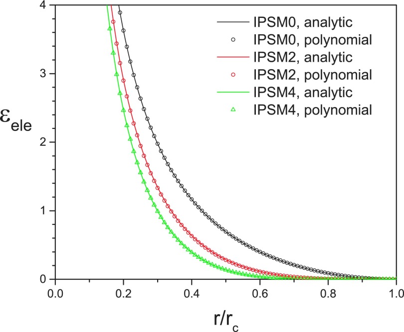
Table II lists the polynomials that fit well to the IPS multipole potentials given in Eq. (16) for m = 0–10 and their root-mean-square deviations from Eq. (16). Fig. 1 show the IPS multipole potentials and their polynomial fittings for m = 0, 2, and 4. As can be seen from Fig. 1 and Table II, the polynomials fit very well to the analytic expressions given in Eq. (16). The polynomials with m ≥ 2 listed in Table II are the lowest order polynomials that satisfy the multipole IPS boundary condition, Eq. (17). For the multipole interaction of the mth order, the lowest order polynomial given by Eq. (18) has m + 2 coefficients, b0, b1, …, bm+1, which can be solved analytically from the multipole IPS boundary condition, Eq. (17). Obviously, the more terms in the polynomial function, Eq. (18), the better fit we can achieve. However, for high order multipole interactions with m ≥ 2, we found that more terms do not produce noticeably better simulation results.
TABLE II.
The fit polynomial functions for the multipole IPS potentials. The root-mean-square deviation (RMSD) is calculated against Eq. (16).
| Order | Pairsa | Fit functions | RMSD |
|---|---|---|---|
| 0 | M-M | 1.7 × 10⁻³ | |
| 1 | M-D | 5.4 × 10⁻⁴ | |
| 2 | N-Q | 6.9 × 10⁻³ | |
| D-D | |||
| 3 | M-O | 2.2 × 10⁻³ | |
| D-Q | |||
| 4 | M-16th | 6.9 × 10⁻⁴ | |
| D-O | |||
| Q-Q | |||
| 5 | M-32nd | 2.2 × 10⁻⁴ | |
| D-16th | |||
| Q-O | |||
| 6 | M-64th | 7.1 × 10⁻⁵ | |
| D-32nd | |||
| Q-16th | |||
| O-O | |||
| 7 | M-128th | 2.3 × 10⁻⁵ | |
| D-64th | |||
| Q-32nd | |||
| O-16th | |||
| 8 | M-256th | 7.5 × 10⁻⁶ | |
| D-128th | |||
| Q-64th | |||
| O-32nd | |||
| 16th-16th | |||
| 9 | M-512nd | 2.4 × 10⁻⁶ | |
| D-256th | |||
| Q-128th | |||
| O-64th | |||
| 16th-32nd | |||
| 10 | M-1024th | 8.0 × 10⁻⁷ | |
| D-512nd | |||
| Q-256th | |||
| O-128th | |||
| 16th-64th | |||
| 32nd-32nd |
Monopole, dipole, quadrupole, and octopole are denoted as M, D, Q, and O, respectively. Hexadecapole and higher are denoted by their numerical orders.
FIG. 1.
IPSMm potentials and their polynomial fittings for m = 0, 2, and 4.
From Table II we can see that the nonpolar 3D IPS electrostatic potential (IPSn)53 is the multipole IPS electrostatic potential of order 0, IPSM0, and the polar 3D IPS electrostatic potential (IPSp) we proposed previously53 is the multipole IPS electrostatic potential of order 2, IPSM2.
C. Algorithm of the IPS method
To summarize the multipole IPS method, we list the calculated equations for multipole IPS interactions. We use a charge-dipole-quadrupole system as an example to show the calculation of multipole IPS potentials.
For this charge-dipole-quadrupole system, the maximum interaction order is m = 4. We chose the IPSM4 to illustrate the calculation,
| (19) |
Here, χ is a scaling factor that many force fields employ to adjust contribution from covalent bonded atom pairs, which typically takes the following form:
| (20) |
For the AMOEBA force field,46 . When χ = 1, Eq. (19) and its derivatives up to the 5th order are continuous at r = rc. Note that the covalent bonding adjusting only applies to the direct interaction part, , not the long-range IPS image part because image atoms are at least rc distance away and are not directly covalent-bonded with the central atom. Therefore, the total energy is the sum over all atom pairs within rc, including the excluded atoms (such as self-pairs and covalent-bonded pairs, which are normally excluded in nonbonded interactions).
From Eqs. (12) and (19) we can calculate S0 through S5,
| (21a) |
| (21b) |
| (21c) |
| (21d) |
| (21e) |
| (21f) |
For the charge-dipole-quadrupole system, the energy calculation needs S0 through S4, while the force calculation needs S1 through S5. With the S vector and the direction vectors, Eq. (13), we can calculate all tensors according to Eq. (11).
The IPSMm potentials are implemented into the AMBER Sander program.54 The implementation is based on Sagui’s implementation of the AMOEBA force field.24 Many details of the multipole interaction, including global frame transformation, torque treatment, etc., can be found in Sagui’s paper.24 With the IPSMm potentials, only atom pairs within the local region are calculated as described above. The calculation in reciprocal space is completely avoided. Using the vector relation proposed in this work, tensors are directly calculated without recursion.
III. SIMULATION DETAILS
The multipole IPS potentials, IPSMm, for m = 0–5, are examined against PME, energy shift (ESH), and force switch (FSW) methods. The FSW method applies a switching function to smoothly taper each multipole interaction energy to zero between the distances ron and roff,43
| (22) |
The switch-on distance was set to ron = rc − 2 Å as recommended by the authors.1
The energy shift (ESH) method shifts only the charge-charge electrostatic energy function,1
| (23) |
and all interactions of higher order are calculated according to Eq. (10) based on the tensors,
| (24) |
For the particle-mesh-Ewald (PME) method,15,55 the 5th order b-spline interpolation was used. The grid size was around 0.466 Å and the Ewald coefficient, β, was set to be 0.45 Å−1.24 To focus the comparison on electrostatic interactions, Lennard-Jones interactions were calculated with the original method of AMOEBA with the same cutoff distance of 10 Å.45,46 The cutoff distance, rc, which, for IPS, is also the local region radius, was varied for multipole interactions to examine its effect on simulation results.
To compare the IPSMm potential of different orders, we modified the AMOEBA water to have various polarities as shown in Table III. We use M, D, and Q to denote the type of multipoles in the model systems. For example, as shown in Table III, system M has only monopoles and system MQ has monopoles and quadrupoles. These model systems contain multipoles up to the order of 2 and correspondingly have interactions up to the order of 4. To demonstrate the application of the IPSMm potential in real protein simulations, we present the simulations of an aqueous solution of dihydrofolate reductase (DHFR) with the polarizable AMEOBA force field. All model systems were simulated for 0.5 ns to evaluate their energetic, structural, and dynamic properties. The SHAKE algorithm56 was used to fix bond lengths. A time step of 1 fs was used for all simulations, except for the NVE simulations where the time step was 0.1 fs and bond lengths were not constrained. All of the simulations (except the NVE simulations) were performed at a constant temperature of T = 300 K and a constant volume in a cubic periodic box with a box side of 29.858 Å3. The only exception was the DHFR system which was simulated in a cubic periodic box with a side of 62.23 Å.
TABLE III.
Model systems to examine the IPSMm potentials. Each system contains 890 three-atom molecules. Charges, dipoles, and quadrupoles are all in atomic units.
| System | Monopole | Dipole | Quadrupole |
|---|---|---|---|
| (interaction order) | q | {μx, μy, μz} | {θxx, θyy, θzz, θxy, θyz, θzx} |
| M (m = 0) | μO = μH1 = μH2 = {0, 0, 0} | θO = θH1 = θH2 = {0, 0, 0, 0, 0, 0} | |
| D (m = 2) | qO = qH1 = qH2 = 0 | θO = θH1 = θH2 = {0, 0, 0, 0, 0, 0} | |
| Q (m = 4) | qO = qH1 = qH2 = 0 | μO = μH1 = μH2 = {0, 0, 0} | |
| MD (m = 2) | θO = θH1 = θH2 = {0, 0, 0, 0, 0, 0} | ||
| MQ (m = 4) | μO = μH1 = μH2 = {0, 0, 0} | ||
| DQ (m = 4) | qO = qH1 = qH2 = 0 | ||
| MDQ (m = 4) | |||
| Polarizable (m = 4) |
IV. RESULTS AND DISCUSSION
The IPSMm potentials derived in this work have different interaction orders. Using model systems, we examined the behavior of these potentials and compared them with ESH, FSW, and PME results to produce a guide for selecting the order of the IPSMm potential for multipole systems.
A. Energy conservation in NVE simulation
A basic requirement of a potential function is to be able to conserve energy in a NVE simulation. For methods with limited cutoff distances, typically, it requires both the energy and force to approach zero at the cutoff boundary to conserve energy. For multipole interactions, because the force can be repulsive and attractive depending on the orientation, the overall effects of non-zero forces at the boundary cancel out. As a result, only the pairwise energies are required to approach zero at the cutoff boundary to conserve energy.
The FSW method forces all pairwise energies to be zero at the boundary and can therefore maintain the energy conservation. ESH has a zero charge-charge interaction energy, but a non-zero multipole interaction energy at the boundary for orders other than 0, and therefore will not be able to conserve energy for systems with interaction orders higher than 0. The IPSMm potential of order m produces zero energy for interactions of order m + 1 or lower, which can conserve energy for systems with interaction order of m + 1 or lower.
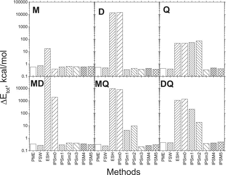
Fig. 2 shows the energy drifts of the model systems during 100 ps NVE simulations with various methods. Note that these energy drifts are as reported by AMBER and do not include a correction for the shadow Hamiltonian.57 PME is a full range method and is expected to conserve energy well. The energy drifts in the PME results are due to numerical errors. Practically, an energy drift comparable to the PME results is regarded as satisfactory in energy conservation.
FIG. 2.
Total energy drifts in NVE simulations with various methods. The simulations were performed for a cubic box of 890 molecules with a time step of 0.1 fs and a cutoff distance of 8 Å. The drifts were calculated over a 100 ps period. Each model system contains 890 three-atom molecules (see Table III).
For system M, where only charge-charge interactions exist, i.e., the maximum interaction order is 0, all IPSMm potentials, as well as FSW and ESH, have zero energies at the boundary. Therefore, all methods conserve energy satisfactorily for system M, as evident by the small energy drifts shown in Fig. 2. The non-zero boundary forces of ESH do cause a larger drift than other methods. For D and MD systems, the maximum interaction order is 2. From Fig. 2 we can see that ESH and IPSM0 cannot satisfactorily conserve the total energy. For Q, MQ, and DQ systems, the maximum interaction order is 4 and ESH, IPSM0, IPSM1, and IPSM2 produced large energy drifts, indicating that they cannot satisfactorily conserve the total energy. These results support that only the potentials with zero boundary energies can conserve energy. As a summary, for a system with the maximum interaction order of k, the IPSMm potential with m ≥ k − 1 can conserve the energy.
B. Energy distributions
Energy distribution reflects the energy surface sampled in molecular simulation. Applying each of the potential calculation methods, we performed NVT simulations to examine the potential energy averages and fluctuations, which are related to heat capacities of the simulation system.
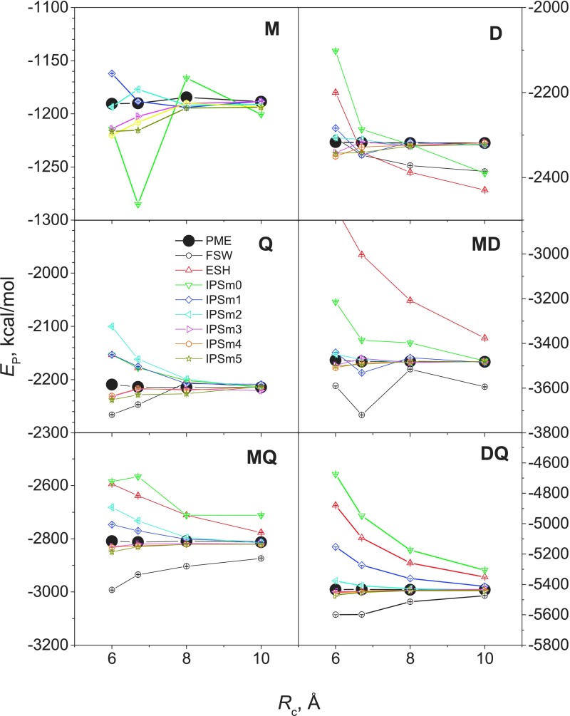
Fig. 3 shows the average energies from these methods at different cutoff distances. The PME results are shown as big dots for an easy comparison. For system M, the results of FSW and ESH are so different from the PME results that cannot be seen in the plot range. The IPSMm potentials produced much closer results to PME and the higher the interaction order, m, is, the closer results it produced.
FIG. 3.
Average potential energies obtained from NVT simulations with different methods at different cutoff distances. Each model system contains 890 three-atom molecules (see Table III).
One important aspect of a calculation method for long-range interactions is the dependence on cutoff distances. Theoretically, PME results are independent of cutoff distances. However, due to numerical errors in calculation, there are certain fluctuations when simulating with different cutoff distances.
Examining the results in Fig. 3, we can see that FSW and ESH have strong cutoff distance dependence for all model systems. IPSM0 and IPSM1 show strong dependence for all systems with m > 0, IPSM2 shows strong dependence for systems with m > 2, and IPSM3, IPSM4, and IPSM5 show little dependence for all model systems (where the maximum interaction orders are 4 or less). This independence to the cutoff distance allows an acceleration of simulation with small cutoff distances without compromising accuracy too much.
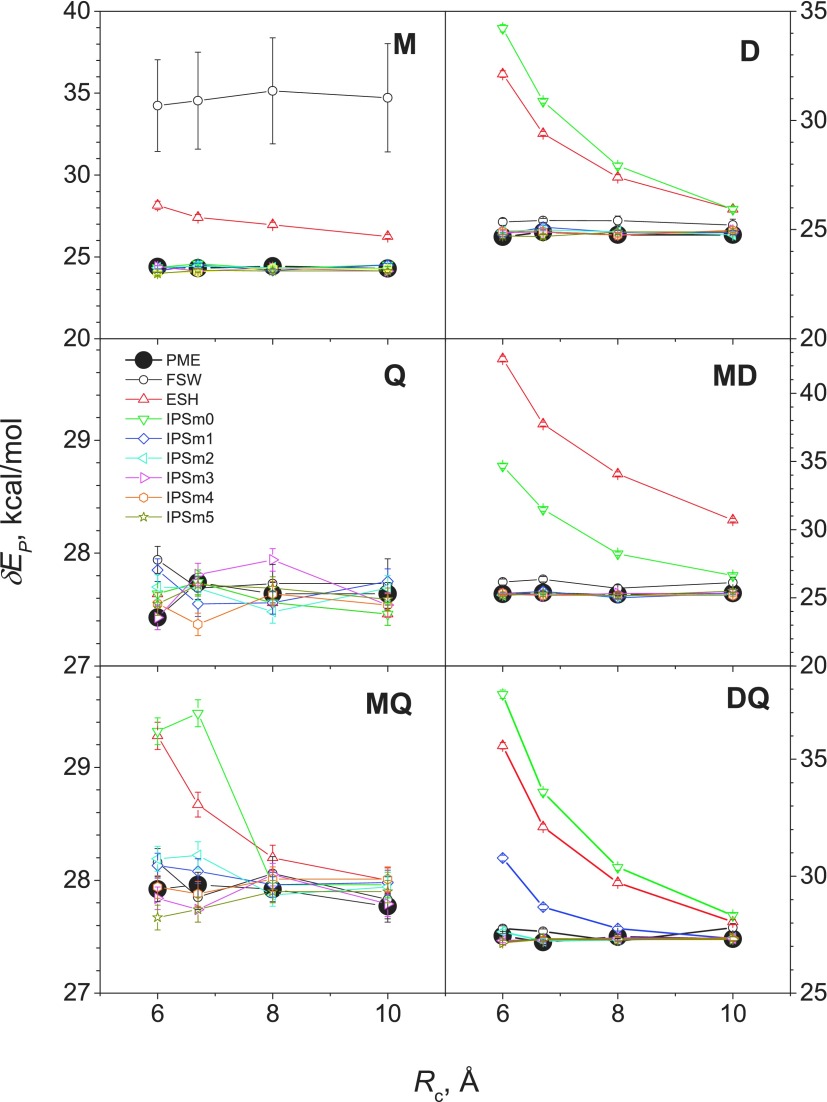
The potential energy is a relative quantity and may shift up or down depending on the choice of the reference state. However, the fluctuation in the potential energy is independent of the reference state and can better describe the energy distribution. The energy fluctuations from different methods at different cutoff distances are shown in Fig. 4. For system M, FSH and ESH fluctuations deviate significantly from the PME results, while all IPSMm potentials produced similar results to PME at all cutoff distances examined. FSW caused system M to freeze, which is why a large difference was observed. ESH and IPSM0 exhibit strong cutoff-distance dependence for D, MD, MQ, and DQ. All IPSMm with an interaction order of 2 or higher produced very similar fluctuation at all cutoff distances. Combined with the energy averages shown in Fig. 3, IPSMm potentials can accurately describe the energy distributions in systems with a maximum interaction order of m + 1 or less at all the cutoff distances examined here.
FIG. 4.
Potential energy fluctuations of the model systems obtained from NVT simulations with different methods at different cutoff distances. Each model system contains 890 three-atom molecules (see Table III).
C. Radial distribution functions (RDFs)
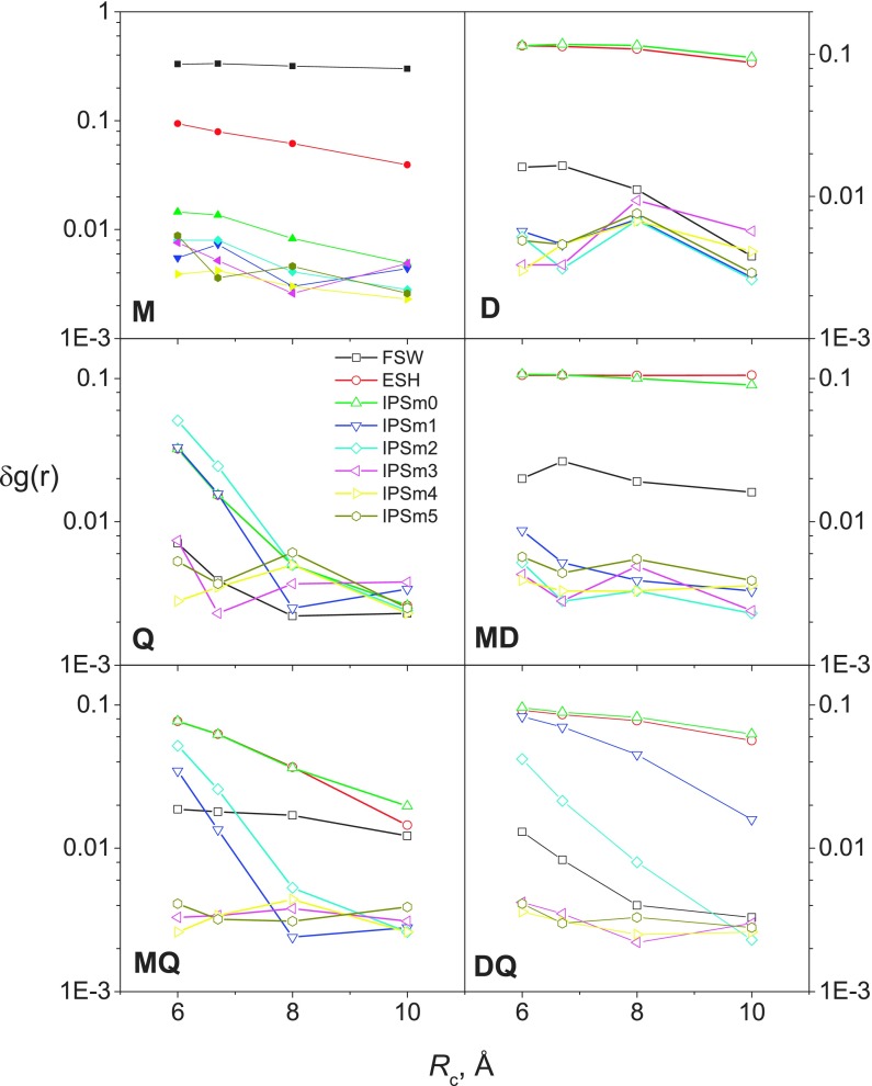
Radial distribution functions (RDFs) are sensitive to potential functions and often show abnormal deviations for cutoff-based methods around the cutoff boundary. We use root-mean-square deviations (RMSDs) in RDFs as compared with the PME results to measure the accuracy in reproducing the PME RDF,
| (25) |
where Ng is the number of data points in the calculated RDF. A RMSD of 0.01 or less indicates a good agreement with the PME result. The RMSD from different methods at different cutoff distances is plotted in Fig. 5.
FIG. 5.
RDF RMSD of various methods at different cutoff distances as compared with the PME results. RDF RMSD was calculated with all atom pairs, including O–O, O–H, and H–H. Each model system contains 890 three-atom molecules (see Table III).
From Fig. 5 we can see that FSW has large RMSD for systems M, M-D, and M-Q, indicating FSW is poor for interactions involving charges. ESH has large rms for all systems except system, Q, which has pure quadrupoles, indicating ESH is poor for interactions involving charges or dipoles. It is clear to see that IPSM0 is poor for all systems except the pure charge system, M, IPSM1 is good only for M and D model systems, while IPSM2 is poor for all quadrupole containing systems, Q, M-Q, and D-Q. IPSM3, IPSM4, and IPSM5 are all similarly good for all systems and show little dependence on cutoff distances. Also we can see that the lower order the IPSMm potential has, the stronger cutoff dependence the results show. In summary, the IPSMm potential is accurate at reproducing the PME RDF for systems with a maximum interaction order of m + 1 or less at all the cutoff distances examined here.
D. Diffusion coefficients
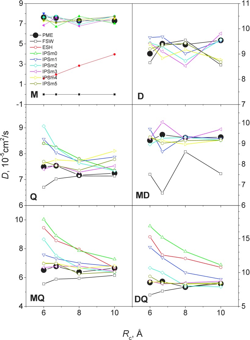
Diffusion is a dynamic property and diffusion coefficient is a convenient quantity for examining interaction calculation methods. An accurate long-range interaction calculation method must preserve the dynamics properties. From the simulations of the model systems, we calculated the diffusion coefficients according to the mean square displacements of heavy atoms. Fig. 6 shows the diffusion coefficients obtained from simulations with various methods and at different cutoff distances. As can be seen, the FSW diffusion coefficients are close to the PME results for systems D, Q, and D-Q. However, the diffusion coefficients are significantly smaller for M, MD, and M-Q, indicating FSW is poor for systems involving charges. ESH produced very different results for all systems and shows strong cutoff distance dependence. The diffusion coefficients of IPSM0 agree with those of PME only for system M. IPSM1 and IPSM2 results agree with the PME results for systems M, D, and M-D. IPSM3, IPSM4, and IPSM5 results are close to the PME results for all systems and at all cutoff distances. From these results we can see again that the IPSMm potentials can well describe the diffusion coefficients in systems with a maximum interaction order of m + 1 or less at all the cutoff distances examined here.
FIG. 6.
Comparison of diffusion coefficients obtained from NVT simulations with different methods at different cutoff distances. Each model system contains 890 three-atom molecules (see Table III).
E. Polarizable water
Multipole interactions are especially important for polarizable force fields.35,45,58 Here we show the application of the IPSMm potentials to the AMOEBA polarizable water45,46 to demonstrate its applicability in polarizable force fields.
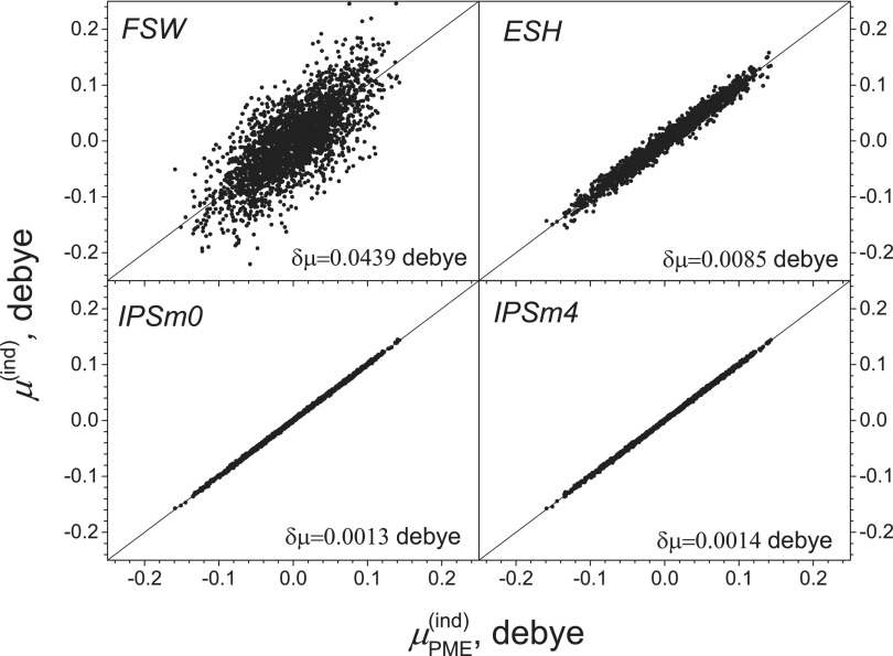
Induced dipole moments measure the local electric field that molecules experience and are critical quantities for a polarizable force field. We first examine induced dipole moments calculated with different methods. Fig. 7 compares atomic induced dipole moments from FSW, ESH, IPSM0, and IPSM4, against that from PME. Clearly, IPSM0 and IPSM4 correlate very well with PME, while FSW and ESH results have significant deviations. The dipole moment RMSD for FSW, ESH, IPSM0, and IPSM4 is 0.0439, 0.0085, 0.0013, and 0.0014 D, respectively.
FIG. 7.
Induced dipole moments of AMOEBA water from FSH, ESH, IPSM0, and IPSM4 are compared against the PME results. A cutoff distance of 8 Å was used for the calculations. The system contains 890 AMOEBA water (see Table III).
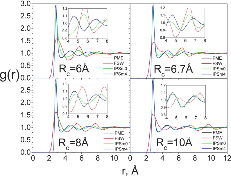
Next, we examine the RDF from different methods at different cutoff distances. Fig. 8 shows the RDFs obtained with PME, FSW, IPSM0, and IPSM4 at different cutoff distances. At rc = 6 Å, the RDFs obtained with FSW and IPSM0 are very different from those obtained with PME, while IPSM4 produced very similar RDFs as PME. As the cutoff distance increases, the RDFs obtained with IPSM0 become closer to those of PME. At Rc = 10 Å, both IPSM0 and IPSM4 methods produced very similar RDFs as PME, while the FSW result still has a significant deviation from the PME result.
FIG. 8.
RDFs of AMOEBA polarizable water from simulations with PME, FSW, IPSM0, and IPSM4 at different cutoff distances. The system contains 890 AMOEBA water (see Table III).
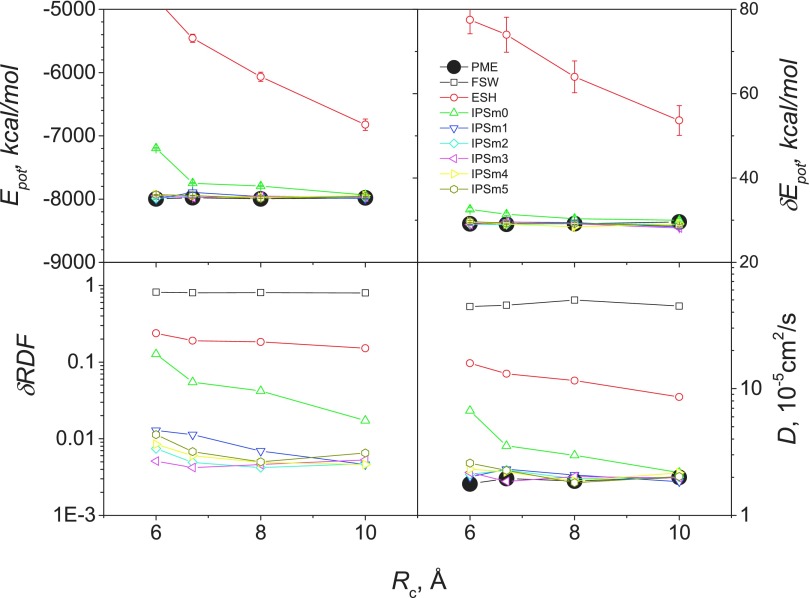
Comparison of different methods is further done with energy, energy fluctuation, RDF RMSD, and diffusion coefficients and the results are shown in Fig. 9. For all the properties examined here, FSW, ESH, and IPSM0 produced significant different results from PME, while IPSM1 through IPSM5 agree well with PME at all cutoff distances examined here. These results demonstrate that IPSM potentials with order of 1 or above can accurately describe the polarizable water with a cutoff distance as small as 6 Å.
FIG. 9.
Ensemble average properties of AMOEBA polarizable water from NVT simulations with different methods. The system contains 890 AMOEBA water (see Table III).
F. Polarizable protein system
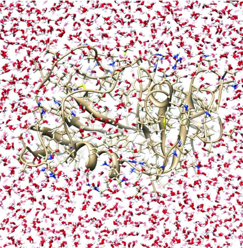
The small cutoff distance used in water simulation can be applied to more heterogeneous systems. Even though the images in a small cutoff range can hardly represent the structures beyond the local region, the difference caused is in the second order and therefore does not have significant effects on long-range interactions. This is the basis to apply IPS potentials to systems with a heterogeneity scale much larger than the cutoff distance. To demonstrate that, we chose the DHFR aqueous solution which is large when compared with the cutoff distance. This is a protein system widely used as a benchmark for molecular simulation (details can be found at http://ambermd.org/amber10.bench1.html). Fig. 10 shows a snapshot of this system. The system contains 23 558 atoms. DHFR has 159 residues with 2489 atoms. There are 7023 AMOEBA water molecules with 21 069 atoms. The system was simulated in a cubic periodic box with a box side of 62.23 Å.
FIG. 10.
A polarizable dihydrofolate reductase (DHFR) in a cubic box of AMOEBA water. There are 159 residues and 7023 water molecules, 21 069 atoms in total. The box side is 62.23 Å.
Because the size of the protein is around 50 Å, much larger than the cutoff distance for the IPSMm potentials, which are typically 10 Å or less, it is not homogeneous in a 10 Å length scale. It is interesting to examine how well the IPSMm potentials describe interactions of this system with small cutoff distances. Table IV lists average potential energies and their fluctuations, as well as the RMSDs of induced dipole moments and the final conformations between simulations with the IPSM4 potential and with PME. As can be seen, the average energies and their fluctuations, simulated with the IPSM4 potential at cutoff distances ranging from 6.0 Å to 10 Å, are very close to the PME result and show little dependence on the cutoff distance. The induced dipole moments with the IPSM4 potential have small deviations from that with PME and the deviation is smaller with larger cutoff distance. The RMSDs of the final conformations obtained with IPSM4 are around 1.3 Å from that obtained with PME. These results demonstrate that the IPSM4 potential can reasonably describe interactions in macromolecule systems with a cutoff distance as small as 6 Å. In other words, molecular interactions beyond the cutoff distance can be well represented with interactions with the isotropic periodic images.
TABLE IV.
Comparison of PME and IPSM4 in the simulation of the polarizable DHFR in AMOEBA water. The averages are calculated over a 10 ps period and the RMSD is between the final conformations from IPSM4 and PME simulations. The simulations were run with a single cpu. The PME simulation uses an 80 × 80 × 80 grid. The induced dipole tolerance is 1 × 10⁻⁵ D.
| Method | rc (Å) | 〈Ep〉 (kcal/mol) | δEp (kcal/mol) | δμ (D) | RMSD (Å) | cpu time (h) |
|---|---|---|---|---|---|---|
| PME | 6.7 | −65 238 ± 63 | 178 ± 18 | 0 | 0 | 36.4 |
| IPSM4 | 6.0 | −65 459 ± 52 | 166 ± 15 | 0.0099 | 1.25 | 10.5 |
| IPSM4 | 6.7 | −65 491 ± 59 | 171 ± 16 | 0.0092 | 1.10 | 13.5 |
| IPSM4 | 8.0 | −65 356 ± 58 | 167 ± 17 | 0.0081 | 1.18 | 20.8 |
| IPSM4 | 10.0 | −65 427 ± 61 | 181 ± 18 | 0.0071 | 1.29 | 39.5 |
When it is desired to fully consider the heterogeneity, a large local region to include the whole system is needed. The IPS/DFFT method proposed previously29 can efficiently handle large cutoff distances which will be the topic of our future development.
Another advantage of using the IPSMm potentials is a faster dipole convergence than using PME. To reach an induced dipole tolerance of 10−5 D with the induced dipole solver which comes with SANDER of AMBER 16,54 27 iterations were needed when using PME while only 18 iterations were needed when using IPSM4. Of course, the iteration numbers can be significantly reduced with better induced dipole solvers and the faster convergence in induce dipole calculation may not be that significant. Combined with the savings in eliminating the reciprocal space calculation and reducing the iteration numbers, the simulation using IPSM4 is much faster than that using PME at the same cutoff distance of 6.7 Å, 14.5 h vs. 40.2 h (see Table IV). For parallel computing, it is expected that IPSMm will scale better because of the poor scalability of FFT in PME calculation.
V. CONCLUSIONS
This work extended the IPS method to multipole interactions by introducing the background homogeneous approximation. Multipole IPS potentials (IPSMm) were derived for the calculation of multipole interactions of order m. Through model systems, we demonstrated that the IPSMm potentials with m ≥ 2 are accurate in describing multipole systems with maximum interaction order of m + 1 or less. The energetic, structural, and dynamic properties obtained with the IPSMm potentials agree well with those with PME. FSW performs very poorly for systems involving charges, while ESH is poor for systems with charges and/or dipoles.
To efficiently calculate multipole interactions in Cartesian space, we proposed a vector relation where a multipole tensor is calculated as a dot product between a radial potential vector and a directional vector. This vector relation can be applied to any type of charge-charge interactions, including the IPSMm potentials. With the IPSMm potentials, long-range multipole interactions are calculated just as easily as with the cutoff methods. Additionally, the calculation cost scales as O(N), while the cost of PME scales as O(NlogN). We have demonstrated that the IPSMm potentials can reproduce PME results to certain accuracy. By eliminating the need of reciprocal space calculation and the associated FFTs, IPSMm potentials have much better scaling performance than PME for massive parallel computing. The IPSMm potentials are especially convenient for polarizable force fields and converge faster than PME.
Because simulations with the IPSMm potentials have little dependence to the cutoff distance when it is 6 Å or larger, the IPSMm potentials allow small cutoff distances to be used to significantly reduce the number of interacting pairs to accelerate simulation. Application to the DHFR protein system demonstrated that a small cutoff around 6 Å can provide reasonably accurate properties.
Because charges (monopoles) often form dipoles in molecular systems and interact mainly in a dipole manner, the IPSMm potentials of the minimum order to use are IPSM2, which is IPSp proposed previously,53 even for systems with only monopoles (charges). Based on our analysis and simulation results, for multipole systems with a maximum interaction order of k, it is recommended to use the IPSMm potentials of order 2 or k − 1, whichever is higher.
Acknowledgments
This research was supported by the Intramural Research Programs of National Heart, Lung, and Blood Institute (Grant No. Z01 HL001027-30). The authors thank Douglas Joubert, NIH Library Writing Center, for manuscript editing assistance.
APPENDIX A: MULTIPOLE INTERACTIONS BETWEEN CHARGES, DIPOLES, AND QUADRUPOLES
To illustrate the calculation of the vector relation, let us consider a multipole systems with charges, dipoles, and quadrupoles, where the highest interaction order is m = 4. To calculate forces, one needs the radial potential vector components with i ≤ m + 1 = 5 and the directional vectors with t + u + v ≤ m + 1 = 5. For convenience, all components with i ≤ 5 in the radial potential vector are explicitly written as follows:
| (A1) |
| (A2) |
| (A3) |
| (A4) |
| (A5) |
| (A6) |
Here, r is the distance between the two interacting sites. All directional vectors with t + u + v ≤ 5 are listed as follows:
| (A7) |
Here, x, y, and z are the coordinate differences between the two interacting sites along the three axes. The directional vector, atuv, has only a few non-zero components and a dot product with the radial potential vector, S, produces only a few non-zero terms. The directional vector can be significantly simplified further if we reorient the interacting multipoles to a frame (x′, y′, z′) with z′ along the radial direction, which we call the quasi-internal frame, so that x′ = 0, y′ = 0, and z′ = r. In the quasi-internal frame, the radial potential vector, S, remains unchanged while the directional vectors, atuv, are changed to and most of are zero except the following vectors (for t + u + v ≤ 5):
| (A8) |
For a charge-dipole-quadrupole system, the multipoles at interaction site i are charges, qi, dipoles, , and quadrupoles, . In the quasi-internal frame, the charges remain to be qi, the dipole is , and the quadrupole is . Here, by substituting Eqs. (A1)–(A8) into Eqs. (11) and (10), we obtain the energies of the multipole interactions listed as follows:
Charge-charge interaction:
| (A9) |
Charge-dipole interaction:
| (A10) |
Charge-quadrupole interaction:
| (A11) |
Dipole-dipole interaction:
| (A12) |
Dipole-quadrupole interaction:
| (A13) |
Quadrupole-quadrupole interaction:
| (A14) |
The second expressions of Eqs. (A10)–(A14) show the calculation in the global frame and the third expressions show the calculation in the quasi-internal frame. Because of the zero values for most components of the directional vectors, the multipole interactions in the vector expressions have many fewer terms than in McMurchie-Davidson recursive expressions. From Eqs. (A10)–(A14) we can see that in the quasi-internal frame, the interaction energies have much simpler form. However, to calculate in the quasi-internal frame, it is required either to rotate the interacting multipoles to the quasi-internal frame, transforming and to and , or to rotate the directional vectors from the quasi-internal frame, , to the global frame, atuv, which could be expensive especially for high orders of multipoles, and in the former case the forces and torques evaluated need to be rotated back to the global frame. But even with the additional cost of rotations, the quasi-internal frame may be beneficial for other reasons27 and will be the topic of our future development. In this work, all calculations were done in the global frame.
APPENDIX B: MULTIPOLE IPS POTENTIALS
The IPSMm potentials given by Eq. (16) can be explicitly written as follows (for m ≤ 5):
| (B1) |
| (B2) |
| (B3) |
| (B4) |
| (B5) |
| (B6) |
where and through are
| (B7) |
| (B8) |
| (B9) |
| (B10) |
| (B11) |
| (B12) |
| (B13) |
| (B14) |
REFERENCES
- 1.Steinbach P. J. and Brooks B. R., J. Comput. Chem. , 667 (1994). 10.1002/jcc.540150702 [DOI] [Google Scholar]
- 2.Wolf D., Keblinski P., Phillpot S. R., and Eggebrecht J., J. Chem. Phys. , 8254 (1999). 10.1063/1.478738 [DOI] [Google Scholar]
- 3.Izvekov S., Swanson J. M. J., and Voth G. A., J. Phys. Chem. B , 4711 (2008). 10.1021/jp710339n [DOI] [PubMed] [Google Scholar]
- 4.Bergdorf M., Peter C., and Hunenberger P. H., J. Chem. Phys. , 9129 (2003). 10.1063/1.1614202 [DOI] [Google Scholar]
- 5.Baker N. A., Helms V., and McCammon J. A., Proteins: Struct., Funct., Genet. , 447 (1999). [DOI] [PubMed] [Google Scholar]
- 6.Barker J. A. and Watts R. O., Mol. Phys. , 789 (1973). 10.1080/00268977300102101 [DOI] [Google Scholar]
- 7.Weeks J. D., Annu. Rev. Phys. Chem. , 533 (2002). 10.1146/annurev.physchem.53.100201.133929 [DOI] [PubMed] [Google Scholar]
- 8.Hunenberger P. H. and van Gunsteren W. F., J. Chem. Phys. , 6117 (1998). 10.1063/1.476022 [DOI] [Google Scholar]
- 9.Denesyuk N. A. and Weeks J. D., J. Chem. Phys. , 124109 (2008). 10.1063/1.2894478 [DOI] [PubMed] [Google Scholar]
- 10.Rodgers J. M. and Weeks J. D., Proc. Natl. Acad. Sci. U. S. A. , 19136 (2008). 10.1073/pnas.0807623105 [DOI] [PMC free article] [PubMed] [Google Scholar]
- 11.Ewald P. P., Ann. Phys. , 253 (1921). 10.1002/andp.19213690304 [DOI] [Google Scholar]
- 12.Shan Y., Klepeis J. L., Eastwood M. P., Dror R. O., and Shaw D. E., J. Chem. Phys. , 54101 (2005). 10.1063/1.1839571 [DOI] [PubMed] [Google Scholar]
- 13.Sagui C. and Darden T., J. Chem. Phys. , 6578 (2001). 10.1063/1.1352646 [DOI] [Google Scholar]
- 14.York D. and Yang W., J. Chem. Phys. , 3298 (1994). 10.1063/1.467576 [DOI] [Google Scholar]
- 15.Essmann U., Perera L., Berkowitz M. L., Darden T., Lee H., and Pedersen L. G., J. Chem. Phys. , 8577 (1995). 10.1063/1.470117 [DOI] [Google Scholar]
- 16.Pollock E. L. and Glosli J., Comput. Phys. Commun. , 93 (1996). 10.1016/0010-4655(96)00043-4 [DOI] [Google Scholar]
- 17.Darden T., York D., and Pedersen L., J. Chem. Phys. , 10089 (1993). 10.1063/1.464397 [DOI] [Google Scholar]
- 18.Giese T. J., Panteva M. T., Chen H., and York D. M., J. Chem. Theory Comput. , 436 (2015). 10.1021/ct5007983 [DOI] [PMC free article] [PubMed] [Google Scholar]
- 19.Kurzak J. and Pettitt B. M., Mol. Simul. , 775 (2006). 10.1080/08927020600991161 [DOI] [PMC free article] [PubMed] [Google Scholar]
- 20.Fenley M. O., Olson W. K., Chua K., and Boschitsch A. H., J. Comput. Chem. , 976 (1996). [DOI] [Google Scholar]
- 21.Cerutti D. S., Duke R. E., Darden T. A., and Lybrand T. P., J. Chem. Theory Comput. , 2322 (2009). 10.1021/ct9001015 [DOI] [PMC free article] [PubMed] [Google Scholar]
- 22.Ghasemi S. A., Neelov A., and Goedecker S., J. Chem. Phys. , 024109 (2007). 10.1063/1.2746328 [DOI] [PubMed] [Google Scholar]
- 23.Hedman F. and Laaksonen A., Chem. Phys. Lett. , 142 (2006). 10.1016/j.cplett.2006.04.106 [DOI] [Google Scholar]
- 24.Sagui C., Pedersen L. G., and Darden T. A., J. Chem. Phys. , 73 (2004). 10.1063/1.1630791 [DOI] [PubMed] [Google Scholar]
- 25.Darden T., Perera L., Li L., and Pedersen L., Structure , R55 (1999). 10.1016/S0969-2126(99)80033-1 [DOI] [PubMed] [Google Scholar]
- 26.York D. M., Wlodawer A., Pedersen L. G., and Darden T. A., Proc. Natl. Acad. Sci. U. S. A. , 8715 (1994). 10.1073/pnas.91.18.8715 [DOI] [PMC free article] [PubMed] [Google Scholar]
- 27.Simmonett A. C., Pickard F., Schaefer H. F. III, and Brooks B. R., J. Chem. Phys. , 184101 (2014). 10.1063/1.4873920 [DOI] [PMC free article] [PubMed] [Google Scholar]
- 28.Wu X. and Brooks B. R., J. Chem. Phys. , 44107 (2005). 10.1063/1.1836733 [DOI] [PMC free article] [PubMed] [Google Scholar]
- 29.Wu X. and Brooks B. R., J. Chem. Phys. , 154115 (2008). 10.1063/1.2992601 [DOI] [PMC free article] [PubMed] [Google Scholar]
- 30.Venable R. M., Chen L. E., and Pastor R. W., J. Phys. Chem. B , 5855 (2009). 10.1021/jp900843x [DOI] [PMC free article] [PubMed] [Google Scholar]
- 31.Ojeda-May P. and Pu J., J. Chem. Phys. , 164106 (2014). 10.1063/1.4871871 [DOI] [PubMed] [Google Scholar]
- 32.Ojeda-May P. and Pu J., J. Chem. Theory Comput. , 134 (2013). 10.1021/ct400724d [DOI] [PubMed] [Google Scholar]
- 33.Wu X. and Brooks B. R., PLoS Comput. Biol. , e1004480 (2015). 10.1371/journal.pcbi.1004480 [DOI] [PMC free article] [PubMed] [Google Scholar]
- 34.Lee J., Miller B. T., and Brooks B. R., Protein Sci. , 231 (2016). 10.1002/pro.2755 [DOI] [PMC free article] [PubMed] [Google Scholar]
- 35.Jakobsen S., Bereau T., and Meuwly M., J. Phys. Chem. B , 3034 (2015). 10.1021/jp508052q [DOI] [PubMed] [Google Scholar]
- 36.Plattner N. and Meuwly M., J. Mol. Model. , 687 (2009). 10.1007/s00894-009-0465-6 [DOI] [PubMed] [Google Scholar]
- 37.Beck B., Rauhut G., and Clark T., J. Comput. Chem. , 1064 (1994). 10.1002/jcc.540151003 [DOI] [Google Scholar]
- 38.Konig G., Mei Y., Pickard F. C. t., Simmonett A. C., Miller B. T., Herbert J. M., Woodcock H. L., Brooks B. R., and Shao Y., J. Chem. Theory Comput. , 332 (2016). 10.1021/acs.jctc.5b00874 [DOI] [PMC free article] [PubMed] [Google Scholar]
- 39.Cazade P. A., Tran H., Bereau T., Das A. K., Klasi F., Hamm P., and Meuwly M., J. Chem. Phys. , 212415 (2015). 10.1063/1.4916630 [DOI] [PubMed] [Google Scholar]
- 40.Cazade P. A., Bereau T., and Meuwly M., J. Phys. Chem. B , 8135 (2014). 10.1021/jp5011692 [DOI] [PubMed] [Google Scholar]
- 41.Kramer C., Bereau T., Spinn A., Liedl K. R., Gedeck P., and Meuwly M., J. Chem. Inf. Model. , 3410 (2013). 10.1021/ci400548w [DOI] [PubMed] [Google Scholar]
- 42.Bereau T., Kramer C., Monnard F. W., Nogueira E. S., Ward T. R., and Meuwly M., J. Phys. Chem. B , 5460 (2013). 10.1021/jp400593c [DOI] [PubMed] [Google Scholar]
- 43.Bereau T., Kramer C., and Meuwly M., J. Chem. Theory Comput. , 5450 (2013). 10.1021/ct400803f [DOI] [PubMed] [Google Scholar]
- 44.Devereux M., Plattner N., and Meuwly M., J. Phys. Chem. A , 13199 (2009). 10.1021/jp903954t [DOI] [PubMed] [Google Scholar]
- 45.Ponder J. W. et al. , J. Phys. Chem. B , 2549 (2010). 10.1021/jp910674d [DOI] [PMC free article] [PubMed] [Google Scholar]
- 46.Ren P. and Ponder J. W., J. Comput. Chem. , 1497 (2002). 10.1002/jcc.10127 [DOI] [PubMed] [Google Scholar]
- 47.Tan M. L., Tran K. N., Pickard F., Simmonett A. C., Brooks B. R., and Ichiye T., J. Phys. Chem. B , 1833 (2016). 10.1021/acs.jpcb.5b09565 [DOI] [PubMed] [Google Scholar]
- 48.Simmonett A. C., Pickard F., Shao Y., Cheatham T. E. III, and Brooks B. R., J. Chem. Phys. , 074115 (2015). 10.1063/1.4928530 [DOI] [PMC free article] [PubMed] [Google Scholar]
- 49.McMurchie L. E. and Davidson E. R., J. Comput. Phys. , 218 (1978). 10.1016/0021-9991(78)90092-X [DOI] [Google Scholar]
- 50.Challacombe M., Schwegler E., and Almlöf J., Chem. Phys. Lett. , 67 (1995). 10.1016/0009-2614(95)00597-W [DOI] [Google Scholar]
- 51.Hättig C., Chem. Phys. Lett. , 521 (1997). 10.1016/S0009-2614(97)00206-6 [DOI] [Google Scholar]
- 52.Hättig C., Chem. Phys. Lett. , 341 (1996). 10.1016/0009-2614(96)00952-9 [DOI] [Google Scholar]
- 53.Wu X. and Brooks B. R., J. Chem. Phys. , 024107 (2009). 10.1063/1.3160730 [DOI] [PMC free article] [PubMed] [Google Scholar]
- 54.Case D. A. et al. , AMBER 2016 (University of California, San Francisco, 2016). [Google Scholar]
- 55.Feller S. E., Pastor R. W., Rojnuckarin A., Bogusz S., and Brooks B. R., J. Phys. Chem. , 17011 (1996). 10.1021/jp9614658 [DOI] [Google Scholar]
- 56.Ryckaert J. P., Ciccotti G., and Berendsen H. J. C., J. Comput. Phys. , 327 (1977). 10.1016/0021-9991(77)90098-5 [DOI] [Google Scholar]
- 57.Zhou J., Reich S., and Brooks B. R., J. Chem. Phys. , 7919 (2000). 10.1063/1.481393 [DOI] [Google Scholar]
- 58.Shi Y., Xia Z., Zhang J., Best R., Wu C., Ponder J. W., and Ren P., J. Chem. Theory Comput. , 4046 (2013). 10.1021/ct4003702 [DOI] [PMC free article] [PubMed] [Google Scholar]


