Abstract
Ultrasound computed tomography (USCT) holds great promise for improving the detection and management of breast cancer. Because they are based on the acoustic wave equation, waveform inversion-based reconstruction methods can produce images that possess improved spatial resolution properties over those produced by ray-based methods. However, waveform inversion methods are computationally demanding and have not been applied widely in USCT breast imaging. In this work, source encoding concepts are employed to develop an accelerated USCT reconstruction method that circumvents the large computational burden of conventional waveform inversion methods. This method, referred to as the waveform inversion with source encoding (WISE) method, encodes the measurement data using a random encoding vector and determines an estimate of the sound speed distribution by solving a stochastic optimization problem by use of a stochastic gradient descent algorithm. Both computer-simulation and experimental phantom studies are conducted to demonstrate the use of the WISE method. The results suggest that the WISE method maintains the high spatial resolution of waveform inversion methods while significantly reducing the computational burden.
Index Terms: Ultrasound computed tomography, Breast imaging, Waveform inversion, Source encoding, Sound speed imaging
I. Introduction
After decades of research [1]–[4], advancements in hardware and computing technologies are now facilitating the clinical translation of ultrasound computed tomography (USCT) for breast imaging applications [2], [5]–[8]. USCT holds great potential for improving the detection and management of breast cancer since it provides novel acoustic tissue contrasts, is radiation- and breast-compression-free, and is relatively inexpensive. [9], [10]. Several studies have reported the feasibility of USCT for characterizing breast tissues [2], [4]–[6], [10], [11]. Although some USCT systems are capable of generating three images that depict the breast's acoustic reflectivity, acoustic attenuation, and sound speed distributions, this study will focus on the reconstruction of the sound speed distribution.
A variety of USCT imaging systems have been developed for breast sound speed imaging [5], [7], [10], [12]–[15]. In a typical USCT experiment, acoustic pulses that are generated by different transducers are employed, in turn, to insonify the breast. The resulting wavefield data are measured by an array of ultrasonic transducers that are located outside of the breast. Here and throughout the manuscript, a transducer that produces an acoustic pulse will be referred to as an emitter; the transducers that receive the resulting wavefield data will be referred to as receivers. From the collection of recorded wavefield data, an image reconstruction method is utilized to estimate the sound speed distribution within the breast [5], [7], [10].
The majority of USCT image reconstruction methods for breast imaging investigated to date have been based on approximations to the acoustic wave equation [12], [16]–[24]. A relatively popular class of methods is based on geometrical acoustics, and are commonly referred to as ‘ray-based’ methods. These methods involve two steps. First, time-of-flight (TOF) data corresponding to each emitter-receiver pair are estimated [25]. Under a geometrical acoustics approximation, the TOF data are related to the sound speed distribution via an integral geometry, or ray-based, imaging model [16], [26]. Second, by use of the measured TOF data and the ray-based imaging model, a reconstruction algorithm is employed to estimate the sound speed distribution. Although ray-based methods can be computationally efficient, the spatial resolution of the images they produce is limited due to the fact that diffraction effects are not modeled [23], [27]. This is undesirable for breast imaging applications, in which the ability to resolve fine features, e.g., tumor spiculations, is important for distinguishing healthy from diseased tissues.
USCT reconstruction methods based on the acoustic wave equation, also known as full-wave inverse scattering or waveform inversion methods, have also been explored for a variety of applications including medical imaging [12], [22], [23], [28] and geophysics [29]–[31]. Because they account for higher-order diffraction effects, waveform inversion methods can produce images that possess higher spatial resolution than those produced by ray-based methods [23], [28]. However, conventional waveform inversion methods are iterative in nature and require the wave equation to be solved numerically a large number of times at each iteration. Consequently, such methods can be extremely computationally burdensome. For special geometries [12], [32], efficient numerical wave equation solvers have been reported. However, apart from special cases, the large computational burden of waveform inversion methods has hindered their widespread application.
A natural way to reduce the computational complexity of the reconstruction problem is to reformulate it in a way that permits a reduction in the number of times the wave equation needs to be solved. In the geophysics literature, source encoding methods have been proposed to achieve this [29]–[31]. When source encoding is employed, at each iteration of a prescribed reconstruction algorithm, all of the acoustic pulses produced by the emitters are combined (or ‘encoded’) by use of a random encoding vector. The measured wavefield data are combined in the same way. As a result, the wave equation may need to be solved as few as twice at each algorithm iteration. In conventional waveform inversion methods, this number would be equal to twice the number of emitters employed. Although conventional waveform inversion methods may require fewer algorithm iterations to obtain a specified image accuracy compared to source encoded methods, as demonstrated later, the latter can greatly reduce the overall number of times the wave equation needs to be solved.
In this study, a waveform inversion with source encoding (WISE) method for USCT sound speed reconstruction is developed and investigated for breast imaging with a circular transducer array. The WISE method determines an estimate of the sound speed distribution by solving a stochastic optimization problem by use of a stochastic gradient descent algorithm [30], [33]. Unlike previously studied waveform inversion methods that were based on the Helmholtz equation [22], [23], the WISE method is formulated by use of the time-domain acoustic wave equation [34]–[36] and utilizes broad-band measurements. The wave equation is solved by use of a computationally efficient k-space method that is accelerated by use of graphics processing units (GPUs). In order to mitigate the interference of the emitter on its neighboring receivers, a heuristic data replacement strategy is proposed. The method is validated in computer-simulation studies that include modeling errors and other physical factors. The practical applicability of the method is further demonstrated in studies involving experimental breast phantom data.
The remainder of the paper is organized as follows. In Section II, USCT imaging models in their continuous and discrete forms are reviewed. A conventional waveform inversion method and the WISE method for sound speed reconstruction are formulated in Section III. The computer-simulation studies and corresponding numerical results are presented in Sections IV and V, respectively. In Section VI, the WISE method is further validated in experimental breast phantom studies. Finally, the paper concludes with a discussion in Section VII.
II. Background: USCT imaging models
In this section, imaging models that provide the basis for image reconstruction in waveform inversion-based USCT are reviewed.
A. USCT imaging model in its continuous form
Although a digital imaging system is properly described as a continuous-to-discrete (C-D) mapping (See Chapter 7 in [37]), for simplicity, a USCT imaging system is initially described in its continuous form below.
In USCT breast imaging, a sequence of acoustic pulses is transmitted through the breast. We denote each acoustic pulse by sm(r,t) ∈ 𝕃2(ℝ3 × [0,∞)), where each pulse is indexed by an integer m for m = 0, 1, ⋯, M − 1 with M denoting the total number of acoustic pulses. Although it is spatially localized at the emitter location, each acoustic pulse can be expressed as a function of space and time. When the m-th pulse propagates through the breast, it generates a pressure wavefield distribution denoted by pm(r,t) ∈ 𝕃2(ℝ3 × [0,∞)). If acoustic absorption and mass density variations are negligible, pm(r,t) in an unbounded medium satisfies the acoustic wave equation [38]:
| (1) |
where c(r) is the sought-after sound speed distribution. Equation (1) can be expressed in operator form as
| (2) |
where the linear operator ℋc : 𝕃2(ℝ3 × [0,∞)) ↦ 𝕃2(ℝ3 × [0,∞)) denotes the action of the wave equation and is independent of the index of m. The superscript ‘c’ indicates the dependence of ℋc on c(r).
Consider that pm(r,t) is recorded outside of the object for r ∈ Ωm and t ∈ [0,T], where Ωm ⊂ ℝ3 denotes a continuous measurement aperture. In this case, when discrete sampling effects are neglected, the imaging model can be described as a continuous-to-continuous (C-C) mapping as:
| (3) |
where gm(r,t) ∈ 𝕃2(Ωm × [0, T]) denotes the measured data function and the operator ℳm is the restriction of ℋc to Ωm × [0, T]. The m-dependent operator ℳm allows Eqn. (3) to describe USCT imaging systems in which the measurement aperture varies with emitter location. Here and throughout the manuscript, we will refer to the process of firing one acoustic pulse and acquiring the corresponding wavefield data as one data acquisition indexed by m. The USCT reconstruction problem in its continuous form is to estimate the sound speed distribution c(r) by use of Eqn. (3) and the data functions .
B. USCT imaging model in its discrete forms
A digital imaging system is accurately described by a continuous-to-discrete (C-D) imaging model, which is typically approximated in practice by a discrete-to-discrete (D-D) imaging model to facilitate the application of iterative image reconstruction algorithms. A C-D description of the USCT imaging system is provided in Appendix A. Below, a D-D imaging model for waveform-based USCT is presented. This imaging model will be employed subsequently in the development of the WISE method in Section III.
Construction of a D-D imaging model requires the introduction of a finite-dimensional approximate representations of the functions c(r) and sm(r,t), which will be denoted by the vectors c ∈ ℝN and sm ∈ ℝNL. Here, N and L denote the number of spatial and temporal samples, respectively, employed by the numerical wave equation solver. In waveform-based USCT, the way in which c(r) and sm(r,t) are discretized to form c and sm is dictated by the numerical method employed to solve the acoustic wave equation. In this study, we employ a pseudospectral k-space method [34]–[36]. Accordingly, c(r) and sm(r,t) are sampled on Cartesian grid points as
| (4) |
where Δt denotes the temporal sampling interval and rn denotes the location of the n-th point.
For a given c and sm, the pseudospectral k-space method can be described in operator form as
| (5) |
where the matrix Hc is of dimension NL × NL and represents a discrete approximation of the wave operator ℋc defined in Eqn. (2), and the vector represents the estimated pressure data at the grid point locations and has the same dimension as sm. The superscript ‘a’ indicates that these values are approximate, i.e., . We refer the readers to [34]–[36] for additional details regarding the pseudospectral k-space method.
Because the pseudospectral k-space method yields sampled values of the pressure data on a Cartesian grid, a sampling matrix Mm is introduced to model the USCT data acquisition process as
| (6) |
Here, the NrecL × NL sampling matrix Mm extracts the pressure data corresponding to the receiver locations on the measurement aperture Ωm, with Nrec denoting the number of receivers. The vector denotes the predicted data that approximates the true measurements. In principle, Mm can be constructed to incorporate transducer characteristics, such as finite aperture size and temporal delays. For simplicity, we assume that the transducers are point-like in this study. When the receiver and grid point locations do not coincide, an interpolation method is required. As an example, when a nearest-neighbor interpolation method is employed, the elements of Mm are defined as
| (7) |
where [Mm]nrecL+l,nL+l denotes the element of Mm at the (nrecL+l)-th row and the (nL+l)-th column, and ℐm(nrec) denotes the index of the grid point that is closest to r(m, nrec). Here, r(m, nrec) denotes the location of the nrec-th receiver in the m-th data acquisition. Equation (6) represents the D-D imaging model that will be employed in the remainder of this study.
III. Waveform inversion with source encoding for USCT
A. Sequential waveform inversion in its discrete form
A conventional waveform inversion method that does not utilize source encoding will be employed as a reference for the developed WISE method and is briefly described below. Like other conventional approaches, this method sequentially processes the data acquisitions gm for m = 0, 1, ⋯, M − 1 at each iteration of the associated algorithm. As such, we will refer to the conventional method as a sequential waveform inversion method.
A sequential waveform inversion method can be formulated as a non-linear numerical optimization problem:
| (8) |
where ℱ(c), ℛ(c), and β denote the data fidelity term, the penalty term, and the regularization parameter, respectively. The data fidelity term ℱ(c) is defined as a sum of squared ℓ2-norms of the data residuals corresponding to all data acquisitions as:
| (9) |
where gm ∈ ℝNrecL denotes the measured data vector at the m-th data acquisition. The choice of the penalty term will be addressed in Section IV.
The gradient of ℱ(c) with respect to c, denoted by J, will be computed by discretizing an expression for the Fréchet derivative that is derived assuming a continuous form of Eqn. (9). The Fréchet derivative is described in Appendix B. Namely, the gradient is approximated as
| (10) |
where Jm denotes the gradient of with respect to c and the vector contains samples that approximate adjoint wavefield qm(r,t) that satisfies Eqn. (34) in Appendix B. By use of the pseudospectral k-space method, can be calculated as
| (11) |
where
| (12) |
Here, ℕm = {n : ℐm(nrec), nrec = 0, 1, ⋯, Nrec − 1}, and denotes the inverse mapping of ℐm.
Given the explicit form of J in Eqn. (10), a variety of optimization algorithms can be employed to solve Eqn. (8) [39]. Algorithm 1 describes a gradient descent-based sequential waveform inversion method. Note that at every algorithmic iteration, the sequential waveform inversion method updates the sound speed estimate only once using the gradient J accumulated over all Jm for m = 0, 1, ⋯, M − 1. This is unlike the Kaczmarz method—also known as the algebraic reconstruction technique [16], [19], [40]—that updates the sound speed estimate multiple times in one algorithmic iteration. In Line-10 of Algorithm 1, JR denotes the gradient of ℛ(c) with respect to c.
|
| |
| Algorithm 1 Gradient descent-based sequential waveform inversion. | |
|
| |
| Input: {gm}, {sm}, c(0) | |
| Output: ĉ | |
| 1: | k ← 0 {k is the number of algorithm iteration.} |
| 2: | while stopping criterion is not satisfied do |
| 3: | k ← k + 1 |
| 4: | J ← 0 |
| 5: | for m := 0 to M − 1 do |
| 6: | {m is the index of the emitter.} |
| 7: | {τm is calculated via Eqn. (12).} |
| 8: | J ← J + Jm {Jm is calculated via Eqn. (10).} |
| 9: | end for |
| 10: | J ← J + βJR |
| 11: | Determine step size λ via a line search |
| 12: | c(k) ← c(k−1) − λJ |
| 13: | end while |
| 14: | ĉ = c(k) |
|
| |
In Algorithm 1, Hc is the most computationally burdensome operator, representing one run of the wave equation solver. Note that it appears in Lines-6, -7, and -11. Because Lines-6 and -7 have to be executed M times to process all of the data acquisitions, the wave equation solver has to be executed at least (2M + 1) times at each algorithm iteration. The line search in Line-11 searches for a step size along the direction of −J so that the cost function is reduced by use of a classic trial-and-error approach [39]. Note that, in general, the line search will require more than one application of Hc, so (2M + 1) represents a lower bound on the total number of wave equation solver runs per iteration.
B. Stochastic optimization-based waveform inversion with source encoding (WISE)
In order to alleviate the large computational burden presented by sequential waveform inversion methods (e.g., Algorithm 1), a source encoding method has been proposed [22], [29], [41]. This method has been formulated as a stochastic optimization problem and solved by various stochastic gradient-based algorithms [30], [31]. In this section, we adapt the stochastic optimization-based formulation in [30] to find the solution of Eqn. (8).
The WISE method seeks to minimize the same cost function as the sequential waveform inversion method, namely, Eqn. (8). However, to accomplish this, the data fidelity term in Eqn. (9) is reformulated as the expectation of a random quantity as [29]–[31], [33], [41], [42]
| (13) |
where Ew denotes the expectation operator with respect to the random source encoding vector w ∈ ℝM, M ≡ Mm is the sampling matrix that is assumed to be identical for m = 0, 1, ⋯, M − 1, and gw and sw denote the w-encoded data and source vectors, defined as
| (14) |
respectively. It has been demonstrated that Eqns. (9) and (13) are mathematically equivalent when w possesses a zero mean and an identity covariance matrix [30], [33], [42]. In this case, the optimization problem whose solution specifies the sound speed estimate can be re-expressed in a stochastic framework as
| (15) |
which we refer to as the waveform inversion with source encoding (WISE) method. An implementation of the WISE method that utilizes the stochastic gradient descent algorithm is summarized in Algorithm 2.
In Algorithm 2, the wave equation solver needs to be run one time in each of Lines-5 and 6. In the line search to determine the step size in Line 8, the wave equation solver needs to be run at least one time, but in general will require a small number of additional runs, just as in Algorithm 1. Accordingly, the lower bound on the number of required wave equation solver runs per iteration is 3, as opposed to (2M +1) for the conventional sequential waveform inversion method described by Algorithm 1. As demonstrated in geophysics applications [29], [31], [41] and the breast imaging studies below, the WISE method provides a substantial reduction in reconstruction times over use of the standard sequential waveform inversion method. In Line-7, Jw can be calculated analogously to Eqn. (10) as
|
| |
| Algorithm 2 Waveform inversion with source encoding (WISE) algorithm. | |
|
| |
| Input: {gm}, {sm}, c(0) | |
| Output: ĉ | |
| 1: | k ← 0 {k is the number of algorithm iteration} |
| 2: | while stopping criterion is not satisfied do |
| 3: | k ← k + 1 |
| 4: | Draw elements of w from independent and identical Rademacher distribution. |
| 5: | pw ← Hcsw {sw is calculated via Eqn. (14).} |
| 6: | qw ← Hcτw {τw is calculated via Eqn. (17).} |
| 7: | J ← Jw + βJR {Jw is calculated via Eqn. (16)} |
| 8: | Determine step size λ by use of line search |
| 9: | c(k) ← c(k−1) − λJ |
| 10: | end while |
| 11: | ĉ = c(k) |
|
| |
| (16) |
where pw = Hcsw and qw = Hcτw with τw ∈ ℝNL calculated by
| (17) |
Here, we drop the subscript m of both ℐ−1(n) and ℕ because we assume M to be identical for all data acquisitions. Various probability density functions have been proposed to describe the source encoding vector w [29], [31], [41]. In this study, we employed a Rademacher distribution as suggested by [29], in which case each element of w had a 50% chance of being either +1 or −1.
IV. Description of computer-simulation studies
Two-dimensional computer-simulation studies were conducted to validate the WISE method for breast sound speed imaging and demonstrate its computational advantage over the standard sequential waveform inversion method.
A. Measurement geometry
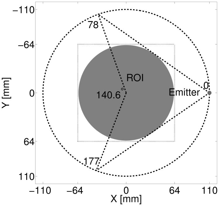
A circular measurement geometry was chosen to emulate a previously reported USCT breast imaging system [10], [23], [43]. As depicted in Fig. 1, 256 ultrasonic transducers were uniformly distributed on a ring of radius 110 mm. The generation of one USCT data set consisted of M = 256 sequential data acquisitions. In each data acquisition, one emitter produced an acoustic pulse. The acoustic pulse was numerically propagated through the breast phantom and the resulting wavefield data were recorded by all transducers in the array as described below. Note that the location of the emitter in every data acquisition was different from those in other acquisitions, while the locations of receivers were identical for all acquisitions.
Fig. 1.
Schematic of a USCT system with a circular transducer array whose elements are indexed from 0 to 255. It shows the first data acquisition, where element-0 (in red) is emitting an acoustic pulse, while all 256 elements are receiving signals. The region-of-interest (ROI) is shaded in gray, and the dashed square box represents the physical dimensions (128 × 128 mm2) of all reconstructed images.
B. Numerical breast phantom
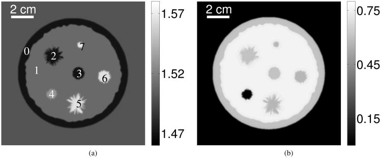
A numerical breast phantom of diameter 98 mm was employed. The phantom was composed of 8 structures representing adipose tissues, parenchymal breast tissues, cysts, benign tumors, and malignant tumors, as shown in Fig. 2. For simplicity, the acoustic attenuation of all tissues was described by a power law with a fixed exponent y = 1.5 [44]. The corresponding sound speed and the attenuation slope values are listed in TABLE I [44]–[46]. Both the sound speed and the attenuation slope distributions in Fig. 2 were sampled on a uniform Cartesian grid with spacing Δs = 0.25 mm. The finest structure (indexed by 7 in Fig. 2-(a)) was of diameter 3.75 mm.
Fig. 2.
(a) Sound speed map [mm·μs−1] and (b) acoustic attenuation slope map [dB·(MHz)−y·cm−1] of the numerical breast phantom.
Table I. Parameters of the numerical breast phantom [44]–[46].
| Structure index | Tissue type | Sound speed [mm·μs−1] | Slope of attenuation [dB·(MHz)−y·cm−1] |
|---|---|---|---|
|
| |||
| 0 | Adipose | 1.47 | 0.60 |
| 1 | Parenchyma | 1.51 | 0.75 |
| 2 | Benign tumor | 1.47 | 0.60 |
| 3 | Benign tumor | 1.47 | 0.60 |
| 4 | Cyst | 1.53 | 0.00217 |
| 5 | Malignant tumor | 1.565 | 0.57 |
| 6 | Malignant tumor | 1.565 | 0.57 |
| 7 | Malignant tumor | 1.57 | 0.57 |
C. Simulation of the measurement data
1) First-order numerical wave equation solver
Acoustic wave propagation in acoustically absorbing media was modeled by three coupled first-order partial differential equations [47]:
| (18a) |
| (18b) |
| (18c) |
where u(r,t), p(r,t), and ρ(r) denote the acoustic particle velocity, the acoustic pressure, and the acoustic density, respectively. The functions τ(r) and η(r) describe acoustic absorption and dispersion during the wave propagation [47]:
| (19) |
where α0(r) and y are the attenuation slope and the power law exponent, respectively. When the medium is assumed to be lossless, i.e., α0(r) = 0, it can be shown that Eqn. (18) is equivalent to Eqn. (1).
Based on Eqn. (18), a pseudospectral k-space method was employed to simulate acoustic pressure data [36], [47]. This method was implemented by use of a first-order numerical scheme on GPU hardware. The calculation domain was of size 512 × 512 mm2, sampled on a 2048 × 2048 uniform Cartesian grid of spacing Δs = 0.25 mm. A nearest-neighbor interpolation was employed to place all transducers on the grid points. On a platform consisting of dual quad-core CPUs with a 3.30 GHz clock speed, 64 gigabytes (GB) of random-accessing memory (RAM), and a single NVIDIA Tesla K20 GPU, the first-order pseudospectral k-space method required approximately 108 seconds to complete one forward simulation.
2) Acoustic excitation pulse
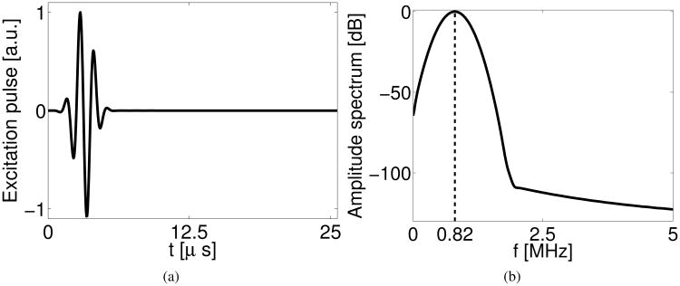
The excitation pulse employed in this study was assumed to be spatially localized at the emitter location while temporally it was a fc = 0.8 MHz sinusoidal function tapered by a Gaussian kernel with standard deviation σ = 0.5 μs, i.e.,
| (20) |
where the constant time shift tc = 3.2 μs. The temporal profile and the amplitude frequency spectrum of the excitation pulse are plotted in Fig. 3-(a) and -(b), respectively. The excitation pulse contained approximately 3 cycles.
Fig. 3.
(a) Normalized temporal profile and (b) amplitude spectrum of the excitation pulse employed in the computer-simulation studies. The dashed line in (b) marks the center frequency of excitation pulse at 0.82 MHz.
3) Generation of non-attenuated and attenuated noise-free data
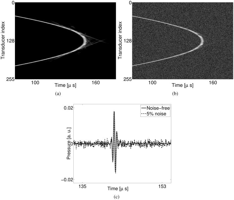
For every data acquisition (indexed by m), the first-order pseudospectral k-space method was run for 3600 time steps with a time interval Δt = 0.05 μs (corresponding to a 20 MHz sampling rate). Downsampling the recorded data by taking every other time sample resulted in a data vector gm (see Eqn. (9)) that was effectively sampled at 10 MHz and was of dimensions ML with M = 256 and L = 1800. The data vector at the 0-th data acquisition, g0, is displayed as a 2D image in Fig. 4-(a). This undersampling procedure was introduced to avoid inverse crime [48] so that the data generation and the image reconstruction employed different numerical discretization schemes. Repeating the calculation for m = 0, 1, ⋯, 255, we obtained a collection {gm} of data vectors that together represented one complete data set. Utilizing the absorption phantom described in Section IV-B, a complete attenuated data set was computed. An idealized, non-attenuated, data set was also computed by setting α0(r) = 0.
Fig. 4.
Computer-simulated (a) noise-free and (b) noisy data vectors at the 0-th data acquisition. (c) Profiles of the pressure received by the 128-th transducer. The grayscale window for (a) and (b) is [−45, 0] dB.
4) Generation of incomplete data
An incomplete data set in this study corresponds to one in which only Nrec receivers located on the opposite side of the emitter record the pressure wavefield, with Nrec < M. Taking the 0-th data acquisition as an example (see Fig. 1), only Nrec = 100 receivers, indexed from 78 to 177, record the wavefield, while other receivers record either unreliable or no measurements. Incomplete data sets formed in this way can emulate two practical scenarios: (1) Signals recorded by receivers near the emitter are unreliable and therefore discarded [23]; and (2) An arc-shaped transducer array is employed that rotates with the emitter [13], [14], [49].
Specifically, incomplete data sets were generated as
| (21) |
where is the incomplete m-th data acquisition, which is of dimensions NrecL, with Nrec < M. The index map is defined as
| (22) |
where (m′ mod M) calculates the remainder of m′ divided by M, and the index set collects indices of transducers that reliably record data at the m-th data acquisition and is defined as
| (23) |
Here, for simplicity, we assume that M and Nrec are even numbers. In this study, we empirically set Nrec = 100 so that the object can be fully covered by the fan region as shown in Fig. 1.
5) Generation of noisy data
An additive Gaussian white noise model was employed to simulate electronic measurement noise as
| (24) |
where g̃m and ñ are the noisy data vector and the Gaussian white noise vector, respectively. In this study, the maximum value of the pressure received by the 128-th transducer at the 0-th data acquisition with a homogeneous medium (water tank) was chosen as a reference signal amplitude. The noise standard deviation was set to be 5% of this value. An example of a simulated noiseless and noisy data acquisition is shown Fig. 4.
D. Image reconstruction
1) Second-order pseudospectral k-space method
In the reconstruction methods described below, the action of the operator Hc (Eqn. (5)) was computed by solving Eqn. (1) by use of a second-order pseudospectral k-space method. This was implemented using GPUs. The calculation domain was of size 512 × 512 mm2, sampled on a 1024 × 1024 uniform Cartesian grid of spacing Δs = 0.5 mm for reconstruction. On a platform consisting of dual octa-core CPUs with a 2.00 GHz clock speed, 125 GB RAM, and a single NVIDIA Tesla K20C GPU, the second-order k-space method required approximately 7 seconds to complete one forward simulation.
2) Sequential waveform inversion
To serve as a reference for the WISE method, we implemented the sequential waveform inversion method described in Algorithm 1. No penalty term was included (β = 0) because, due to its extreme computational burden, we only investigated this method in preliminary studies involving noise-free non-attenuated data. A uniform sound speed distribution was employed as the initial guess, which corresponded to the known background value of 1.5 mm/μs. The object was contained in a square region-of-interest (ROI) of dimension 128 × 128 mm2 (See Fig. 1), which was covered by 256 × 256 pixels.
3) WISE method
We implemented the WISE method by use of Algorithm 2. Two types of penalties were employed in this study: a quadratic penalty expressed as
| (25) |
where Nx and Ny denote the number of grid points along the ‘x’ and ‘y’ directions respectively, and a total variation (TV) penalty, defined as [50], [51]
| (26) |
where ε is a small number introduced to avoid dividing by 0 in the gradient calculation. In this study, we empirically selected ε = 10−8. This value was fixed because we observed that it had a minor impact on the reconstructed images compared to the impact of β. The use of this parameter can be avoided when advanced optimization algorithms are employed [52], [53]. As in the sequential waveform inversion case, it was assumed that the background sound speed was known and the object was contained in a square ROI of dimension 128 × 128 mm2 (See Fig. 1), which corresponded to 256 × 256 pixels. The regularization parameters corresponding to the quadratic penalty and the TV penalty will be denoted by βQ and βTV, respectively. Optimal regularization parameter values should ultimately be identified by use of task-based measures of image quality [37]. In this preliminary study, we investigated the impact of βQ and βTV on the reconstructed images by sweeping their values over a wide range.
4) Reconstruction from incomplete data
Because the WISE method requires Mm to be identical for all m's, image reconstruction from incomplete data remains challenging [30], [33], [42]. In this study, two data completion strategies were investigated [30], [33], [42] to synthesize a complete data set, from which the WISE method could be effectively applied.
One strategy was to fill the missing data with pressure corresponding to a homogeneous medium as
| (27) |
for mrec = 0, 1, ⋯, M − 1, where , denote the computer-simulated (with a homogeneous medium), the measured incomplete, and the combined complete data vectors at the m-th data acquisition, respectively. The mapping denotes the inverse operator of 𝒥m as
| (28) |
This data completion strategy is based on the assumption that the back-scatter from breast tissue in an appropriately sound speed-matched water bath is weak. This assumption suggests that the missing measurements can be replaced by the corresponding pressure data that would have been produced in the absence of the object.
The second, more crude, data completion strategy was to simply fill the missing data with zeros, i.e.,
| (29) |
where denotes the data completed with the second strategy.
5) Bent-ray image reconstruction
A bent-ray method was also employed to reconstruct images. Details regarding the time-of-flight estimation and algorithm implementation are provided in Appendix C.
V. Computer-simulation results
A. Images reconstructed from idealized data
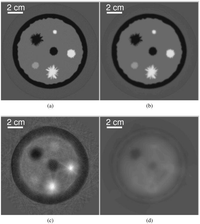
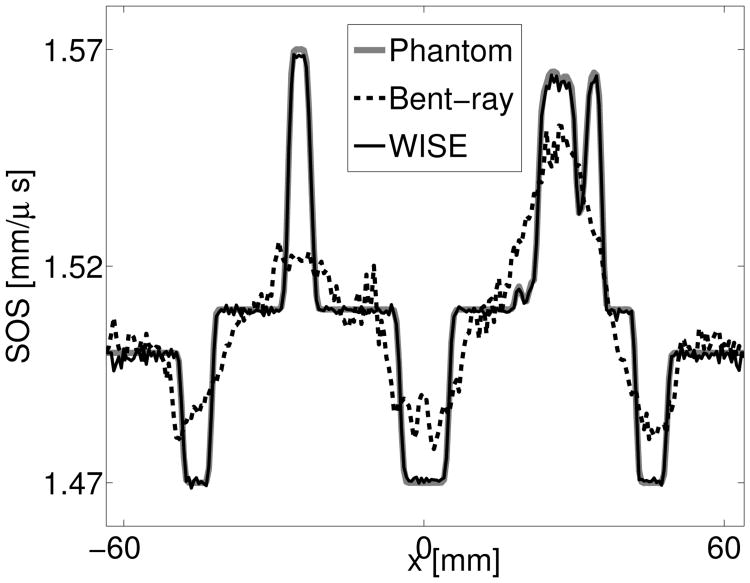
The images reconstructed from the noise-free, non-attenuated, data by use of the WISE method with 199 iterations and the sequential waveform inversion method with 43 iterations are shown in Fig. 5-(a) and (b). As expected [23], [54], both images are more accurate and possess higher spatial resolution than the one reconstructed by use of the bent-ray reconstruction algorithm displayed in Fig. 5-(c). Profiles through the reconstructed images are displayed in Fig. 6. The images shown in Fig. 5-(a) and -(b) possess similar accuracies as measured by their root-mean-square errors (RMSEs), namely, 1.08 × 10⁻³ for the former and 1.19 × 10⁻³ for the latter. The RMSE was computed as the Euclidean distance between the reconstructed image and the sound speed phantom vector c, averaged by the 256 × 256 pixels of the ROI sketched in Fig. 1. However, the reconstruction of Fig. 5-(a) required only about 1.7% of the computational time required to reconstruct Fig. 5-(b), namely, 1.4 hours for the former and 81.4 hours for the latter respectively. This is because the WISE method required only 1018 wave equation solver runs which is significantly less than the 57088 wave equation solver runs required by the sequential waveform inversion method. With a similar number of wave equation solver runs, (e.g., 1024), one can complete only a single algorithm iteration by use of the sequential waveform inversion method. The corresponding image, shown in Fig. 5-(d), lacks quantitative accuracy as well as qualitative value for identifying features. The results suggest that the WISE method maintains the advantages of the sequential waveform inversion method while significantly reducing the computational time.
Fig. 5.
Images reconstructed by use of (a) the WISE method after the 199-th iteration (1, 018 runs of the wave equation solver), (b) the sequential waveform inversion algorithm after the 43-rd iteration (57, 088 runs of the wave equation solver), (c) the bent-ray model-based sound speed reconstruction method, and (d) the sequential waveform inversion algorithm after the 1-st iteration (1, 024 runs of the wave equation solver) from the noise-free non-attenuated data. The grayscale window is [1.46,1.58] mm/μs.
Fig. 6.
Profiles at y = 6.5 mm of the images reconstructed by use of the bent-ray TOF image reconstruction method and the WISE method from the noise-free non-attenuated data.
B. Convergence of the WISE method
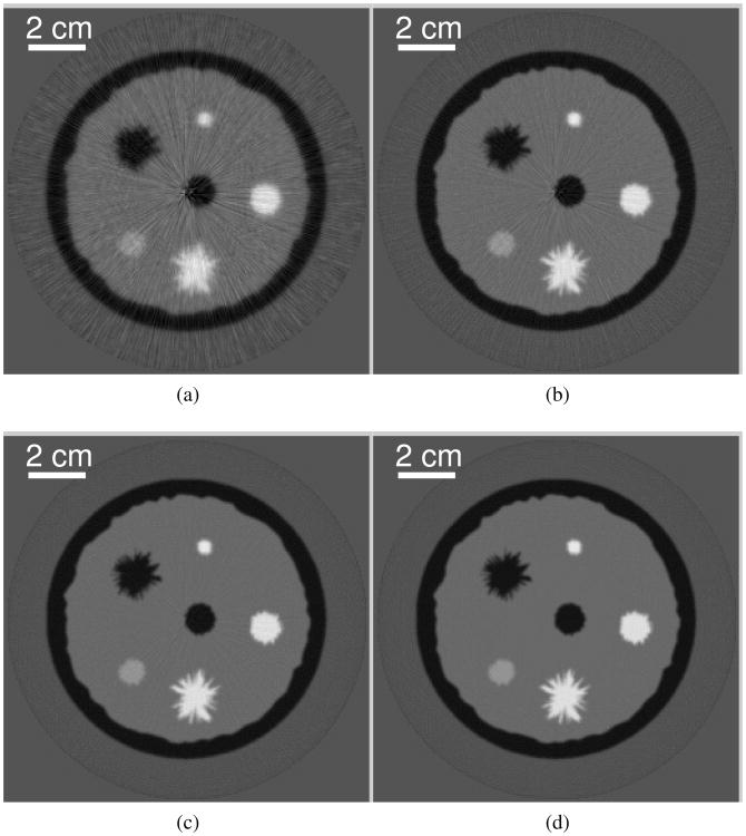
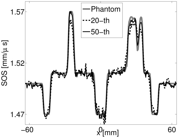
Images reconstructed from noise-free, non-attenuated, data by use of the WISE method contain radial streak artifacts when the algorithm iteration number is less than 100, as shown in Figs. 7-(a-c). Profiles through these images are displayed in 8. The streaks artifacts are likely caused by crosstalk introduced during the source encoding procedure [31], [41]. However, these artifacts are effectively mitigated after more iterations as demonstrated by the image reconstructed after the 199-th iteration in Fig. 5-(a) and its profile in Fig. 6. The quantitative accuracy of the reconstructed images is improved with more iterations as shown in Fig. 8.
Fig. 7.
Images reconstructed by use of the WISE method after (a) the 20-th, (b) the 50-th, (c) the 100-th, and (d) the 250-th iteration from the noise-free, non-attenuated data set. The grayscale window is [1.46,1.58] mm/μs.
Fig. 8.
Profiles of the images reconstructed by use of the WISE method from the noise-free non-attenuated data after different numbers of iterations.
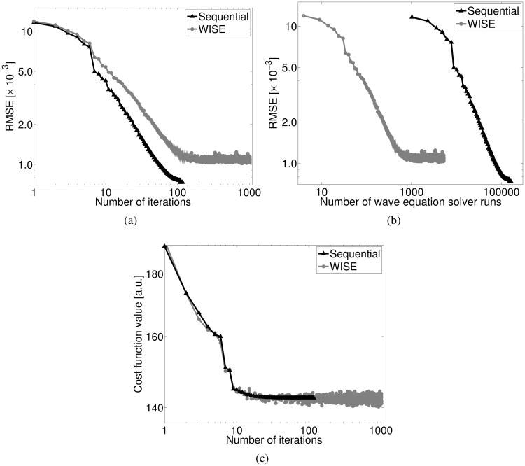
Figure 9-(a) reveals that the WISE method requires a larger number of algorithm iterations than does the sequential waveform inversion method to achieve the same RMSE. The RMSE of the images reconstructed by use of the WISE method appears to oscillate around 1.0 × 10⁻³ after the first 100 iterations while the sequential waveform inversion method can achieve a lower RMSE. However, as shown previously in Fig. 5-(a) and the corresponding profile in Fig. 6, after additional iterations the image reconstructed by use of the WISE method achieves a high accuracy. Moreover, to achieve the same accuracy as the sequential waveform inversion method, the WISE method requires a computation time that is reduced by approximately two-orders of magnitude, as suggested by Fig. 9-(b). We also plotted the cost function value against the number of iterations in Fig. 9-(c). Note that for the WISE method, the cost function value was approximated by the current realization of . These plots suggest that, in this particular case, the WISE method appears to approximately converge after 200 iterations. For example, the images reconstructed after 199 (Fig. 5-(a)) and 250 (Fig. 7-(d)) iterations are nearly identical.
Fig. 9.
Plots of the root-mean-square errors (RMSEs) of the images reconstructed from the noise-free data versus (a) the number of iterations and (b) the number of wave equation solver runs. (c) Plots of the cost function value versus the number of iterations.
C. Images reconstructed from non-attenuated data containing noise
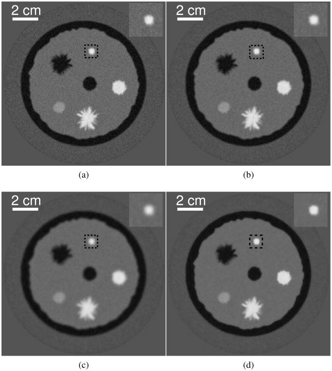
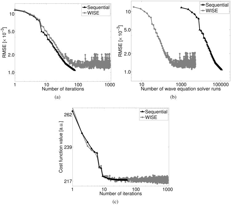
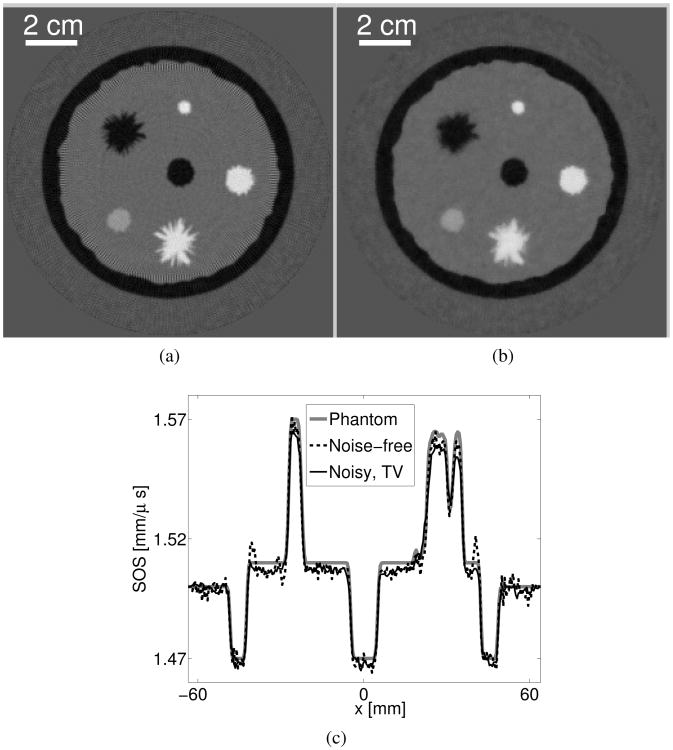
Images reconstructed by use of the WISE method with a quadratic penalty and the WISE method with a TV penalty from noisy, non-attenuated, data are presented in Fig. 10. All images were obtained after 1024 algorithm iterations. The WISE method with a quadratic penalty effectively mitigates image noise as shown in Figs. 10-(a-c), at the expense of image resolution, as expected. Figure 10-(d) shows an image reconstructed by use of the WISE method with a TV penalty. The image appears to possess a similar resolution but a lower noise level than the image in Fig. 10-(b) that was reconstructed by use of the WISE method with a quadratic penalty. We also compared the convergence rates of the WISE method and the sequential waveform inversion methods when both utlize a TV penalty and the same regularization parameter. As shown in Fig. 11, the convergence properties of the penalized methods follow similar trends as the un-penalized methods, which were discussed above and shown in Fig. 9. Even though it required a larger number of algorithm iterations, the WISE method reduced the computation time by approximately two-orders of magnitude as compared to the sequential waveform inversion method.
Fig. 10.
Images reconstructed from non-attenuated data contaminated with Gaussian random noise. Images (a-c) were reconstructed by use of the WISE method with a quadratic penalty with βQ = 1.0×10⁻³, 1.0×10⁻², and 1.0×10⁻¹, respectively. Image (d) was reconstructed by use of the WISE method with a TV penalty with βTV=5.0×10⁻⁴. The insert in the up right corner of each image is the zoomed-in image of the dashed black box, which contains 35×35 pixels (17.5×17.5mm2). The grayscale window is [1.46,1.58] mm/μs.
Fig. 11.
Plots of the root-mean-square errors (RMSEs) of the images reconstructed from the noisy data versus (a) the number of iterations and (b) the number of wave equation solver runs. (c) Plots of the cost function value versus the number of iterations. Both the WISE and the sequential waveform inversion methods employed a TV penalty with βTV=5.0×10⁻⁴.
D. Images reconstructed from acoustically attenuated data
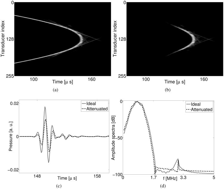
Our current implementation of the WISE method assumes an absorption-free acoustic medium. This assumption can be strongly violated in practice. In order to investigate the robustness of the the WISE method to model errors associated with ignoring medium acoustic absorption, we applied the algorithm to the acoustically attenuated data that were produced as described in Section IV-C. As shown in Fig. 12, when acoustic absorption is considered, the amplitude of the measured pressure is attenuated by approximately a factor of 2. The wavefront (See Fig. 12-(a)) remains very similar to that when medium absorption is ignored (See Fig. 4-(a)). Medium absorption has the largest impact on the pressure data received by transducers located opposite the emitter as shown in Fig. 12-(b). The shape of the pulse profile remains very similar as shown in Fig. 12-(c) and -(d), suggesting that waveform dispersion may be less critical than amplitude attenuation in image reconstruction for this phantom.
Fig. 12.
(a) Computer-simulated noise-free attenuated pressure of the 0-th data acquisition. (b) The difference between the attenuated pressure data and the non-attenuated pressure data. (c) The temporal profiles and (d) the amplitude spectra of the pressure received by the 128-th transducer. The grayscale window for (a) and (b) is [-45, 0] dB.
Images reconstructed by use of the WISE method with a TV penalty from noise-free and noisy attenuated data are shown in Figs. 13-(a) and (b). Image profiles are shown in Fig. 13-(c). Although these images contain certain artifacts that were not produced in the idealized data studies, most object structures remain readily identified. These results suggest that the WISE method with a TV penalty can tolerate data inconsistencies associated with neglecting acoustic attenuation in the imaging model, at least to a certain level with regards to feature detection tasks.
Fig. 13.
(a) Image reconstructed by use of the WISE method from the noise-free attenuated data. (b) Image reconstructed by use of the WISE method with a TV penalty with βTV=5.0×10⁻⁴, from the noisy attenuated data. The grayscale window is [1.46,1.58] mm/μs. (c) Profiles at y = 6.5 mm of the reconstructed images.
E. Images reconstructed from idealized incomplete data
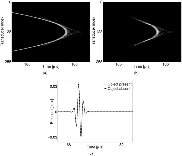
The wavefront of the noise- and attenuation-free pressure wavefield when the object is absent (Fig. 14-(a)) appears to be very similar to that when the object is present (Fig. 4-(a)). As expected, the largest differences are seen in the signals received by the transducers located opposite of the emitter, as shown in Fig. 14-(b). As seen in Fig. 14-(c), the time traces received by the 40-th transducer are nearly identical when object is present and absent. This is because the back-scattered wavefield is weak for breast imaging applications. These results establish the potential efficacy of the data completion strategy of filling the missing data with the pressure data corresponding to a water bath.
Fig. 14.
(a) Computer-simulated noise-free non-attenuated pressure data when the object is absent. (b) The difference between the pressure data when object is present and the pressure data when the object is absent. (c) Profiles of the pressure received by the 40-th transducer. The grayscale window for (a) and (b) is [−45, 0] dB.
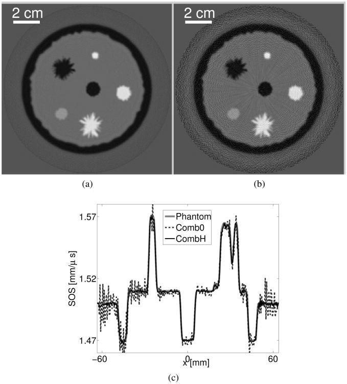
The image reconstructed from the measurements completed with pressure data corresponding to a water bath is shown in Fig.15-(a). As revealed by the profile in Fig.15-(c), this image is highly accurate. Alternatively, the image reconstructed from the the data completed with zeros contains strong artifacts as shown in Fig. 15-(b). These results suggest that the WISE method can be adapted to reconstruct images from incomplete data, which is particularly useful for emerging laser-induced USCT imaging systems [13]–[15].
Fig. 15.
Images reconstructed by use of the WISE method from noise-free combined data that are completed (a) with computer-simulated pressure corresponding to a homogeneous medium and (b) with zeros. The grayscale window is [1.46,1.58] mm/μs. (c) Profiles at y =6.5 mm of the images reconstructed by use of the WISE method from the two combined data sets.
VI. Experimental validation
A. Data acquisition
Experimental data recorded by use of the SoftVue USCT scanner [55] was utilized to further validate the WISE method. The scanner contained a ring-shaped array of radius 110 mm that was populated with 2048 transducer elements. Each element had a center frequency of 2.75 MHz, a pitch of 0.34 mm, and was elevationally focused to isolate a 3 mm thick slice of the to-be-imaged object. The transducer array was mounted in a water tank and could be translated with a motorized gantry in the vertical direction. Readers are referred to [55] for additional details regarding the system.
The breast phantom was built by Dr. Ernie Madsen from the University of Wisconsin and provides tissue-equivalent scanning characteristics of highly scattering, predominantly parenchymal breast tissue. The phantom mimics the presence of benign and cancerous masses embedded in glandular tissue, including a subcutaneous fat layer. Figure 16 displays a schematic of one slice through the phantom. The diameter of the inclusions is approximately 12 mm. Table II presents the known acoustic properties of the phantom.
Fig. 16.
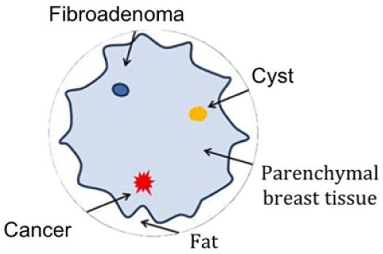
Schematic of the breast phantom employed in the experimental study.
Table II. Parameters of the experimental breast phantom.
| Material | Sound speed [mm·μs−1] | Attenuation coefficient at 2.5 MHz [dB/cm] | |
|---|---|---|---|
|
| |||
| Fat | 1.467 | 0.48 | |
| Parenchymal tissue | 1.552 | 0.89 | |
| Cancer | 1.563 | 1.20 | |
| Fibroadenoma | 1.552 | 0.52 | |
| Gelatin cyst | 1.585 | 0.16 | |
During data acquisition, the breast phantom was placed near the center of the ring-shaped transducer array so that the distance between the phantom and each transducer was approximately the same. While scanning each slice, every other transducer element sequentially emits fan beam ultrasound signals towards the opposite side of the ring. The forward scattered and backscattered ultrasound signals are subsequently recorded by the same transducer elements. The received waveform was sampled at a rate of 12 MHz. The 1024 data acquisitions required approximately 20 seconds in total. A calibration data set was also acquired in which the phantom object was absent.
B. Data pre-processing
48 bad channels were manually identified by visual inspection. After discarding these, the data set contained M = 976 acquisitions. Each acquisition contained Nrec = 976 time traces. Each time trace contained L = 2112 time samples. The 976 good channels were indexed from 0 to 975. The corresponding data acquisitions were indexed in the same way. A Hann-window low-pass filter with a cutoff frequency of 4 MHz was applied to every time trace in both the calibration and the measurement data. This data filtering was implemented to mitigate numerical errors that could be introduced by our second-order wave equation solver.
C. Estimation of excitation pulse
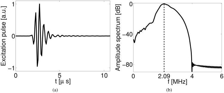
The shape of the excitation pulse was estimated as the time trace of the calibration data (after preprocessing) received by the 488-th receiver at the 0-th data acquisition. Note that the 488-th receiver was approximated located on the axis of the 0-th emitter, thus the received pulse was minimally affected by the finite aperture size effect of the transducers. Because our calibration data and measurement data were acquired using different electronic amplifier gains, the amplitude of the excitation pulse was estimated from the measurement data. More specifically, we simulated the 0-th data acquisition using the second-order pseudospectral k-space method and compared the simulated time trace received by the 300-th receiver with the corresponding measured time trace (after pre-processing). The ratio between the maximum values of these two traces was used to scale the excitation pulse shape. We selected the 300-th receiver because it resided out of the fan-region indicated in Fig. 1; its received signals were unlikely to be strongly affected by the presence of the object. The estimated excitation pulse and its amplitude spectrum are displayed in Fig. 17. Note that the experimental excitation pulse contained higher frequency components than did the computer-simulated excitation pulse shown in Fig. 3.
Fig. 17.
(a) Normalized temporal profile and (b) amplitude spectrum of the excitation pulse employed in the experimental studies. The dashed line in (b) marks the center frequency of excitation pulse at 2.09 MHz.
D. Synthesis of combined data
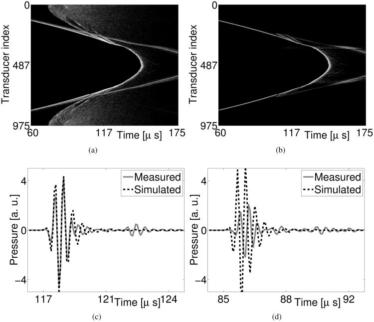
As discussed in Section IV-C4, signals received by receivers located near the emitter can be unreliable [23]. Our experimental data, as shown in Fig. 18-(a), contained noise-like measurements for the receivers indexed from 0 to 200, and from 955 to 975, in the case where the 0-th transducer functioned as the emitter. Also, our point-like transducer assumption introduces larger model mismatches for the receivers located near the emitter. As shown in Figs. 18-(c) and -(d), even though the simulated time trace received by the 300-th receiver matches accurately with the experimentally measured one, the simulated time trace received by the 200-th receiver is substantially different compared with the experimentally measured one. In order to minimize the effects of model mismatch, we replaced these unreliable measurements with computer-simulated water bath data, as described in Section IV-C. We designated the time traces received by the 512 receivers located on the opposite side of the emitter as the reliable measurements for each data acquisition. The 0-th data acquisition of the combined data is displayed in Fig. 18-(b).
Fig. 18.
Zeroth acquisition of (a) the experimentally-measured raw data and (b) the combined data, respectively, and time traces at the 0-th acquisition received by (c) the 300-th receiver, and (d) the 200-th receiver, respectively. The grayscale window for (a) and (b) is [−45, 0] dB.
E. Estimation of initial guess
The initial guess for the WISE method was obtained by use of the bent-ray reconstruction method described in Appendix C. We first filtered each time trace of the raw data by a band-pass Butterworth filter (0.5MHz - 2.5MHz). Subsequently, we extracted the TOF by use of the thresholding method with a thresholding value of 20% of the peak value of each time trace. The bent-ray reconstruction algorithm was applied for image reconstruction with a measured background sound speed 1.513 mm/μs. The resulting image is shown in Fig. 19-(a) and has a pixel size of 1 mm. Finally, the image was smoothed by convolving it with a 2D Gaussian kernel with a standard deviation of 2 mm.
Fig. 19.
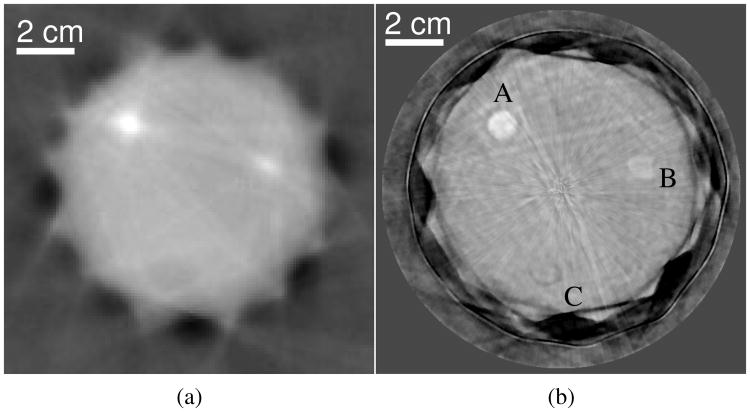
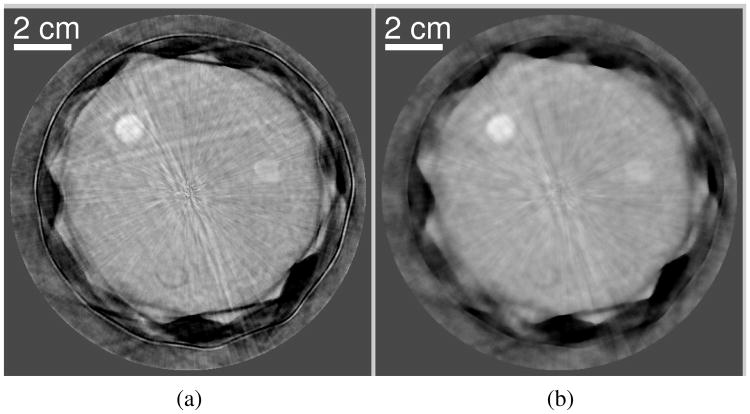
Images reconstructed from the experimentally measured phantom data by use of (a) the bent-ray model-based sound speed reconstruction method and (b) the WISE method with a TV penalty with (βTV =1.0×10²) after the 200-th iteration. The grayscale window is [1.49,1.57] mm/μs.
F. Image reconstruction
We applied the WISE method with a TV penalty to the combined data set. The second-order wave equation solver was employed with a calculation domain of dimensions 512.0 × 512.0 mm2. The calculation domain was sampled on a 2560 × 2560 Cartesian grid with a grid spacing of 0.2 mm. On a platform consisting of dual quad-core CPUs with a 3.30 GHz clock speed, 64 GB RAM, and a single NVIDIA Tesla K20 GPU, each numerical solver run, took 40 seconds to calculate the pressure data for 2112 time samples. Knowing the size of the phantom, we set the reconstruction region to be within a circle of diameter 128 mm, i.e., only the sound speed values of pixels within the circle were updated during the iterative image reconstruction. We swept the value of βTV over a wide range to investigate its impact on the reconstructed images.
G. Images reconstructed from experimental data
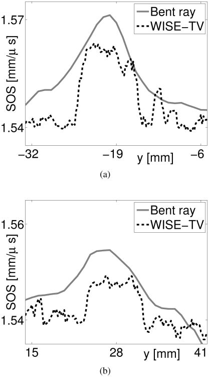
As shown in Fig. 19, the spatial resolution of the image reconstructed by use of the WISE method with a TV penalty is significantly higher than that reconstructed by use of the bent-ray model-based method. In particular, the structures labeled ‘A’ and ‘B’ possess clearly-defined boundaries. This observation is further confirmed by the profiles of the two images shown in Fig. 20. In addition, the structure labeled ‘C’ in Fig. 19-(b) is almost indistinguishable in the image reconstructed by use of the bent-ray model-based method (see Fig. 19-(a)). The improved spatial resolution is expected because the WISE method takes into account high-order acoustic diffraction, which is ignored by the bent-ray method [23]. Though not shown here, for the bent-ray method, we investigated multiple time-of-flight pickers [25] and systematically tuned the regularization parameter. As such, it is likely that Fig. 19-(a) represents a nearly optimal bent-ray image in terms of the resolution. This resolution also appears to be similar to previous experimental results reported in the literature [26].
Fig. 20.
Profiles at (a) x = −24.0 mm and (b) x = 10.0 mm of the reconstructed images by use of the bent-ray model-based sound speed reconstruction method (light solid) and the WISE method with a TV penalty with βTV =1.0×10² (dark dashed) from experimentally measured data.
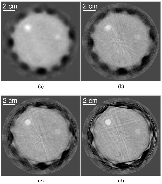
The convergence properties of the WISE method with a TV penalty with experimental data were consistent with those observed in the computer-simulation studies. Images reconstructed by use of 10, 50, and 300 algorithm iterations are displayed in Fig. 21. The image reconstructed by use of 10 iterations contains radial streak artifacts that are similar in nature to those observed in the computer-simulation studies. These artifacts were mitigated after more iterations. The image reconstructed after 300 iterations (Fig. 21-(d)) appears to be similar to that after 200 iterations (Fig. 19-(b)), suggesting that the WISE method with a TV penalty is close to convergence after about 200 iterations. The time required to complete 200 iterations was approximately 14 hours. The estimated time it would take for the sequential waveform inversion method to produce a comparable image is approximately one month, assuming the same number of iterations is required as in the computer-simulation studies (i.e., 40).
Fig. 21.
(a) The initial guess of the sound speed map and the images reconstructed by use of the WISE method with a TV penalty with (βTV = 1.0 ×10²) after (b) the 10-th, (b) the 50-th and (d) the 300-th iteration, from the experimentally measured phantom data. The grayscale window is [1.49, 1.57] mm/μs.
Despite the nonlinearity of the WISE method, the impact of the TV penalty appears to be similar to that observed in other imaging applications [52], [56] (see Fig. 22). Though not shown here, the impact of the quadratic penalty is also similar. As expected, a larger value of β reduced the noise level at the expense of spatial image resolution. These results suggest a predictable impact of the penalties on the images reconstructed by use of the WISE method.
Fig. 22.
Images reconstructed by use of the WISE method with a TV penalty with (a) βTV = 5.0×101, and (b) βTV = 5.0 × 10², from the experimentally measured phantom data. The grayscale window is [1.49, 1.57] mm/μs.
VII. Summary
It is known that waveform inversion-based reconstruction methods can produce sound speed images that possess improved spatial resolution properties over those produced by ray-based methods. However, waveform inversion methods are computationally demanding and have not been applied widely in USCT breast imaging. In this work, based on the time-domain wave equation and motivated by recent mathematical results in the geophysics literature, the WISE method was developed that circumvents the large computational burden of conventional waveform inversion methods. This method encodes the measurement data using a random encoding vector and determines an estimate of the sound speed distribution by solving a stochastic optimization problem by use of a stochastic gradient descent algorithm. With our current GPU-based implementation, the computation time was reduced from weeks to hours. The WISE method was systematically investigated in computer-simulation and experimental studies involving a breast phantom. The results suggest that the method holds value for USCT breast imaging applications in a practical setting.
Many opportunities remain to further improve the performance of the WISE method. As shown in Fig. 19, images reconstructed by use of the WISE method can contain certain artifacts that are not present in the image reconstructed by use of the bent-ray method. An example of such an artifact is the dark horizontal streak below the structure C. Because of the nonlinearity of the image reconstruction problem, it is challenging to determine whether these artifacts are caused by imaging model errors or by the optimization algorithm, which might have arrived at a local minimum of the cost function. A more accurate imaging model can be developed to account for out-of-plane scattering, the transducer finite aperture size effect, acoustic absorption, as well as other physical factors. Also, the stochastic gradient descent algorithm is one of the most basic stochastic optimization algorithms. Numerous emerging optimization algorithms can be employed [33], [42] to improve the convergence rate. In addition, there remains a great need to compare the WISE method with other existing sound speed reconstruction algorithms [19], [40].
There remains a need to conduct additional investigations of the numerical properties of the WISE method. Currently, a systematic comparison of the statistical properties of the WISE and the sequential waveform inversion method is prohibited by the excessively long computation times required by the latter method. This comparison will be interesting when a more efficient wave equation solver is available. Given the fact that waveform inversion is nonlinear and sensitive to its initial guess, it becomes important to investigate how to obtain an accurate initial guess. We also observed that the performance of the WISE method is sensitive to how strong the medium heterogeneities are and the profile of the excitation pulse. An investigation of the impact of the excitation pulse the numerical properties of the image reconstruction may help optimize hardware design. In addition, quantifying the statistics of the reconstructed images will allow application of task-based measures of image quality to be applied to guide system optimization studies.
Acknowledgments
This work was supported in part by NIH awards EB010049, CA167446, EB016963 and DOD Award US ARMY W81XWH-13-1-0233.
Appendix A: Continuous-to-Discrete USCT Imaging Model
In practice, each data function gm(r,t) is spatially and temporally sampled to form a data vector gm ∈ ℝNrecL, where Nrec and L denote the number of receivers and the number of time samples, respectively. We will assume that Nrec and L do not vary with excitation pulse. Let [gm]nrecL+l denotes the (nrecL+l)-th element of gm. When the receivers are point-like, gm is defined as
| (30) |
where the indices nrec and l specify the receiver location and temporal sample, respectively, and Δt is the temporal sampling interval. The vector r(m, nrec) ∈ Ωm denotes the location of the nrec-th receiver at the m-th data acquisition.
A C-D imaging model for USCT describes the mapping of c(r) to the data vector gm and can be expressed as
| (31) |
Note that the acousto-electrical impulse response [57] of the receivers can be incorporated into the C-D imaging model by temporally convolving sm(r, t) in Eqn. (1) with the receivers ' acousto-electrical impulse response if we assume all receiving transducers share an identical acousto-electrical impulse response.
Appendix B: Fréchet derivative of data fidelity term
Consider the integrated squared-error data misfit function, [22], [23]
| (32) |
where gm(r, t) and gm(r, t) denote the measured data function and the predicted data function computed by use of Eqn. (3) with the current estimate of c(r).
Both the sequential and WISE reconstruction method described in Section III require knowledge of the Fréchet derivatives of ℱCC(c) and ℛCC(c) with respect to c, denoted by ∇cℱCC and ∇cℛCC, respectively. The calculation of ∇cℛCC can be readily accomplished for quadratic smoothness penalties [52], [58]. For the integrated squared error data misfit function given in Eqn. (32), ∇cℱCC can be computed via an adjoint state method as [28], [59], [60]
| (33) |
where qm(r, t) ∈ 𝕃2(ℝ3 × [0, ∞)) is the solution to the adjoint wave equation. The adjoint wave equation is defined as
| (34) |
where τm(r, t) = gm(r, T − t) − gm(r, T − t). The adjoint wave equation is nearly identical in form to the wave equation in Eqn. (1) except for the different source term on the right-hand side, suggesting the same numerical approach can be employed to solve both equations. Since one needs to solve Eqns. (1) and (34) M times in order to calculate ∇cℱCC, it is generally true that the sequential waveform inversion is computationally demanding even for a 2D geometry [61].
Appendix C: Bent-ray model-based sound speed reconstruction
We developed an iterative image reconstruction algorithm based on a bent-ray imaging model. The bent-ray imaging model assumes that an acoustic pulse travels along a ray path that connects the emitter and the receiver and accounts for the refraction of rays, also known as ray-bending, through an acoustically inhomogeneous medium. For each pair of receiver and emitter, the travel time, as well as the ray path, is determined by the medium's sound speed distribution. Given the travel times for a collection of emitter-and-receiver pairs distributed around the object, the medium sound speed distribution can be iteratively reconstructed. This bent-ray model-based sound speed reconstruction (BRSR) method has been employed in the USCT literature [26], [62], [63].
In order to perform the BRSR, we extracted a TOF data vector from the measured pressure data. Denoting the TOF data vector by T ∈ ℝMNrec, each element of T represented the TOF from each emitter-and-receiver pair. The extraction of the TOF was conducted in two steps. First, we estimated the difference between the TOF when the object was present and the TOF when the object was absent by use of a thresholding method [25], [64]. In particular, 20% of the peak value of each time trace was employed as the thresholding value. Second, a TOF offset was added to the estimated difference TOF for each emitter-and-receiver pair to obtain the absolute TOF, where the TOF offset was calculated according to the scanning geometry and the known background SOS.
Having the TOF vector T, we reconstructed the sound speed by solving the following optimization problem:
| (35) |
where s denotes the slowness (the reciprocal of the SOS) vector, and Ks denotes the system matrix that maps the slowness distribution to the TOF data. The superscript ‘s’ indicates the dependence of Ks on the slowness map. At each iteration, using the current estimate of the SOS, a ray-tracing method [65] was employed to construct the system matrix Ks. Explicitly storing the system matrix in the sparse representation, we utilized the limited BFGS method [66] to solve the optimization problem given in Eqn. (35). The estimated slowness was then converted to the sound speed by taking the reciprocal of ŝ element-wisely. We refer the readers to [26], [62]–[64], [67] for more details about the BRSR method.
Contributor Information
Kun Wang, Department of Biomedical Engineering, Washington University in St. Louis, St. Louis, MO 63130.
Thomas Matthews, Department of Biomedical Engineering, Washington University in St. Louis, St. Louis, MO 63130.
Fatima Anis, Department of Biomedical Engineering, Washington University in St. Louis, St. Louis, MO 63130.
Cuiping Li, Delphinus Medical Technologies, Plymouth, MI 48170.
Neb Duric, Delphinus Medical Technologies, Plymouth, MI 48170; Karmanos Cancer Institute, Wayne State University, 4100 John R. Street, 5 HWCRC, Detroit, MI 48201.
Mark A. Anastasio, Email: anastasio@wustl.edu, Department of Biomedical Engineering, Washington University in St. Louis, St. Louis, MO 63130.
References
- 1.Glover G. Characterization of in vivo breast tissue by ultrasonic time-of-flight computed tomography. Natl Bur Stand Int Symp Ultrason Tissue Characterization, National Science Foundation, Ultrasonic Tissue Characterization II. 1979:221–225. [Google Scholar]
- 2.Carson P, Meyer C, Scherzinger A, Oughton T. Breast imaging in coronal planes with simultaneous pulse echo and transmission ultrasound. Science. 1981;214(4525):1141–1143. doi: 10.1126/science.7302585. [Online]. Available: http://www.sciencemag.org/content/214/4525/1141.abstract. [DOI] [PubMed] [Google Scholar]
- 3.Schreiman JS, Gisvold JJ, Greenleaf JF, Bahn RC. Ultrasound transmission computed tomography of the breast. Radiology. 1984;150(2):523–530. doi: 10.1148/radiology.150.2.6691113. [Online]. Available: http://pubs.rsna.org/doi/abs/10.1148/radiology.150.2.6691113. [DOI] [PubMed] [Google Scholar]
- 4.André MP, Janée HS, Martin PJ, Otto GP, Spivey BA, Palmer DA. High-speed data acquisition in a diffraction tomography system employing large-scale toroidal arrays. International Journal of Imaging Systems and Technology. 1997;8(1):137–147. [Google Scholar]
- 5.Borup DT, Johnson SA, Natterer F, Olsen SC, Wiskin JW, Wubeling F, Zhang Y. Apparatus and method for imaging with wavefields using inverse scattering techniques. uS Patent 6,005,916 1999 Dec 21;
- 6.Duric N, Littrup P, Poulo L, Babkin A, Pevzner R, Holsapple E, Rama O, Glide C. Detection of breast cancer with ultrasound tomography: First results with the computed ultrasound risk evaluation (CURE) prototype. Medical physics. 2007;34(2):773–785. doi: 10.1118/1.2432161. [DOI] [PubMed] [Google Scholar]
- 7.Ruiter NV, Göbel G, Berger L, Zapf M, Gemmeke H. Realization of an optimized 3D USCT. SPIE Medical Imaging International Society for Optics and Photonics. 2011:796 805–796 805. [Google Scholar]
- 8.Duric N, Roy O, Li C, Schmidt S, Cheng X, Goll J, Kunz D, Bates K, Janer R, Littrup P. Emerging Imaging Technologies in Medicine. CRC Press; 2012. Ultrasound tomography systems for medical imaging; pp. 167–182. [Google Scholar]
- 9.Ruiter NV, Zapf M, Hopp T, Dapp R, Kretzek E, Birk M, Kohout B, Gemmeke H. 3D ultrasound computer tomography of the breast: A new era? European Journal of Radiology. 2012;81(1)(0):S133–S134. doi: 10.1016/S0720-048X(12)70055-4. extended abstracts and Abstracts of the Sixth International Congress on MR-Mammography [Online]. Available: http://www.sciencedirect.com/science/article/pii/S0720048X12700554. [DOI] [PubMed] [Google Scholar]
- 10.Duric N, Littrup P, Roy O, Schmidt S, Li C, Bey-Knight L, Chen X. Breast imaging with ultrasound tomography: Initial results with softvue. Ultrasonics Symposium (IUS), 2013 IEEE International. 2013 Jul;:382–385. [Google Scholar]
- 11.Li C, Duric N, Littrup P, Huang L. In vivo breast sound-speed imaging with ultrasound tomography. Ultrasound in Medicine & Biology. 2009;35(10):1615–1628. doi: 10.1016/j.ultrasmedbio.2009.05.011. [Online]. Available: http://www.sciencedirect.com/science/article/pii/S0301562909002373. [DOI] [PMC free article] [PubMed] [Google Scholar]
- 12.Wiskin J, Borup DT, Johnson SA, Berggren M. Non-linear inverse scattering: High resolution quantitative breast tissue tomography. J Acoust Soc Am. 2012;131(5):3802–3813. doi: 10.1121/1.3699240. [Online]. Available: http://scitation.aip.org/content/asa/journal/jasa/131/5/10.1121/1.3699240. [DOI] [PMC free article] [PubMed] [Google Scholar]
- 13.Manohar S, Willemink RGH, van der Heijden F, Slump CH, van Leeuwen TG. Concomitant speed-of-sound tomography in photoacoustic imaging. Applied Physics Letters. 2007;91:131911. [Google Scholar]
- 14.Zalev J, Herzog D, Clingman B, Miller T, Kist K, Dornbluth NC, McCorvey BM, Otto P, Ermilov S, Nadvoretsky V, et al. Clinical feasibility study of combined optoacoustic and ultrasonic imaging modality providing coregistered functional and anatomical maps of breast tumors. SPIE BiOS International Society for Optics and Photonics. 2012:82 230A–82 230A. [Google Scholar]
- 15.Xia J, Huang C, Maslov K, Anastasio MA, Wang LV. Enhancement of photoacoustic tomography by ultrasonic computed tomography based on optical excitation of elements of a full-ring transducer array. Opt Lett. 2013 Aug;38(16):3140–3143. doi: 10.1364/OL.38.003140. [Online]. Available: http://ol.osa.org/abstract.cfm?URI=ol-38-16-3140. [DOI] [PMC free article] [PubMed] [Google Scholar]
- 16.Kak AC, Slaney M. Principles of Computerized Tomographic Imaging. IEEE Press; 1988. [Google Scholar]
- 17.Lavarello RJ, Oelze ML. Density imaging using inverse scattering. J Acoust Soc Am. 2009;125(2):793–802. doi: 10.1121/1.3050249. [Online]. Available: http://scitation.aip.org/content/asa/journal/jasa/125/2/10.1121/1.3050249. [DOI] [PubMed] [Google Scholar]
- 18.Lavarello RJ, Oelze ML. Density imaging using a multiple-frequency DBIM approach. IEEE T Ultrason Ferr. 2010 Nov;57(11):2471–2479. doi: 10.1109/TUFFC.2010.1713. [DOI] [PubMed] [Google Scholar]
- 19.Hesford AJ, Chew WC. Fast inverse scattering solutions using the distorted born iterative method and the multilevel fast multipole algorithm. J Acoust Soc Am. 2010;128(2) doi: 10.1121/1.3458856. [DOI] [PMC free article] [PubMed] [Google Scholar]
- 20.Huthwaite P, Simonetti F. High-resolution imaging without iteration: a fast and robust method for breast ultrasound tomography. J Acoust Soc Am. 2011;130(3):1721–1734. doi: 10.1121/1.3613936. [Online]. Available: http://scitation.aip.org/content/asa/journal/jasa/130/3/10.1121/1.3613936. [DOI] [PubMed] [Google Scholar]
- 21.Simonetti F. Multiple scattering: The key to unravel the subwavelength world from the far-field pattern of a scattered wave. Phys Rev E. 2006 Mar;73:036619. doi: 10.1103/PhysRevE.73.036619. [Online]. Available: http://link.aps.org/doi/10.1103/PhysRevE.73.036619. [DOI] [PubMed] [Google Scholar]
- 22.Zhang Z, Huang L, Lin Y. Efficient implementation of ultrasound waveform tomography using source encoding. SPIE Medical Imaging International Society for Optics and Photonics. 2012:832 003–832 003. [Google Scholar]
- 23.Pratt RG, Huang L, Duric N, Littrup P. Sound-speed and attenuation imaging of breast tissue using waveform tomography of transmission ultrasound data. Proc SPIE. 2007;6510:65 104S–65 104S–12. [Online]. Available: http://dx.doi.org/10.1117/12.708789. [Google Scholar]
- 24.Huthwaite P, Simonetti F, Duric N. Combining time of flight and diffraction tomography for high resolution breast imaging: Initial in vivo results (l) J Acoust Soc Am. 2012;132(3):1249–1252. doi: 10.1121/1.4742697. [Online]. Available: http://scitation.aip.org/content/asa/journal/jasa/132/3/10.1121/1.4742697. [DOI] [PubMed] [Google Scholar]
- 25.Li C, Huang L, Duric N, Zhang H, Rowe C. An improved automatic time-of-flight picker for medical ultrasound tomography. Ultrasonics. 2009;49(1):61–72. doi: 10.1016/j.ultras.2008.05.005. [DOI] [PMC free article] [PubMed] [Google Scholar]
- 26.Hormati A, Jovanovi I, Roy O, Vetterli M. Robust ultrasound travel-time tomography using the bent ray model. Proc SPIE. 2010;7629:76 290I–76 290I–12. [Online]. Available: http://dx.doi.org/10.1117/12.844693. [Google Scholar]
- 27.Bates R, Smith V, Murch R. Manageable multidimensional inverse scattering theory. Phys Rep. 1991;201(4):185–277. [Online]. Available: http://www.sciencedirect.com/science/article/pii/037015739190026I. [Google Scholar]
- 28.Roy O, Jovanović I, Hormati A, Parhizkar R, Vetterli M. Sound speed estimation using wave-based ultrasound tomography: theory and GPU implementation. SPIE Medical Imaging International Society for Optics and Photonics. 2010:76 290J–76 290J. [Google Scholar]
- 29.Krebs JR, Anderson JE, Hinkley D, Neelamani R, Lee S, Baumstein A, Lacasse MD. Fast full-wavefield seismic inversion using encoded sources. Geophysics. 2009;74(6):WCC177–WCC188. [Google Scholar]
- 30.Haber E, Chung M, Herrmann F. An effective method for parameter estimation with PDE constraints with multiple right-hand sides. SIAM J Optimiz. 2012;22(3):739–757. [Online]. Available: http://epubs.siam.org/doi/abs/10.1137/11081126X. [Google Scholar]
- 31.Moghaddam PP, Keers H, Herrmann FJ, Mulder WA. A new optimization approach for source-encoding full-waveform inversion. Geophysics. 2013;78(3):R125–R132. [Online]. Available: http://geophysics.geoscienceworld.org/content/78/3/R125.abstract. [Google Scholar]
- 32.Wiskin J, Borup D, Johnson S, Andre M, Greenleaf J, Parisky Y, Klock J. Three-dimensional nonlinear inverse scattering: Quantitative transmission algorithms, refraction corrected reflection, scanner design and clinical results. Proceedings of Meetings on Acoustics. 2013;19(1) [Online]. Available: http://scitation.aip.org/content/asa/journal/poma/19/1/10.1121/1.4800267. [Google Scholar]
- 33.Haber E, Chung M. Simultaneous source for non-uniform data variance and missing data. arXiv preprint arXiv 1404.5254. 2014 [Google Scholar]
- 34.Morton KW, Mayers DF. Numerical Solution of Partial Differential Equations: An Introduction. New York, NY, USA: Cambridge University Press; 2005. [Google Scholar]
- 35.Mast T, Souriau L, Liu DL, Tabei M, Nachman A, Waag R. A k-space method for large-scale models of wave propagation in tissue. Ultrasonics, Ferroelectrics and Frequency Control, IEEE Transactions on. 2001 Mar;48(2):341–354. doi: 10.1109/58.911717. [DOI] [PubMed] [Google Scholar]
- 36.Tabei M, Mast TD, Waag RC. A k-space method for coupled first-order acoustic propagation equations. J Acoust Soc Am. 2002;111(1):53–63. doi: 10.1121/1.1421344. [Online]. Available: http://scitation.aip.org/content/asa/journal/jasa/111/1/10.1121/1.1421344. [DOI] [PubMed] [Google Scholar]
- 37.Barrett H, Myers K. Foundations of Image Science. Wiley Series in Pure and Applied Optics; 2004. [Google Scholar]
- 38.Kinsler LE, Frey AR, Coppens AB, Sanders JV. Fundamentals of acoustics. 4th. Wiley; Dec, 2000. [Online]. Available: http://www.amazon.com/exec/obidos/redirect?tag=citeulike07-20&path=ASIN/0471847895. [Google Scholar]
- 39.Nash S, Sofer A. Linear and Nonlinear Programming. New York: McGraw-Hill; 1996. [Google Scholar]
- 40.Hesse MC, Salehi L, Schmitz G. Nonlinear simultaneous reconstruction of inhomogeneous compressibility and mass density distributions in unidirectional pulse-echo ultrasound imaging. Phys Med Biol. 2013;58(17):6163. doi: 10.1088/0031-9155/58/17/6163. [Online]. Available: http://stacks.iop.org/0031-9155/58/i=17/a=6163. [DOI] [PubMed] [Google Scholar]
- 41.Romero LA, Ghiglia DC, Ober CC, Morton SA. Phase encoding of shot records in prestack migration. Geophysics. 2000;65(2):426–436. [Google Scholar]
- 42.Roosta-Khorasani F, van den Doel K, Ascher UM. Data completion and stochastic algorithms for PDE inversion problems with many measurements. CoRR. 2013;abs/1312.0707 [Google Scholar]
- 43.Duric N, Littrup P, Schmidt S, Li C, Roy O, Bey-Knight L, Janer R, Kunz D, Chen X, Goll J, Wallen A, Zafar F, Allada V, West E, Jovanovic I, Li K, Greenway W. Breast imaging with the softvue imaging system: first results. Proc SPIE. 2013;8675:86 750K–86 750K–8. doi: 10.1117/12.2002513. [Online]. Available: http://dx.doi.org/10.1117/12.2002513. [DOI] [PMC free article] [PubMed] [Google Scholar]
- 44.Szabo TL. Diagnostic ultrasound imaging: inside out. Academic Press; 2004. [Google Scholar]
- 45.Glide C, Duric N, Littrup P. Novel approach to evaluating breast density utilizing ultrasound tomography. Medical Physics. 2007;34(2):744–753. doi: 10.1118/1.2428408. [Online]. Available: http://scitation.aip.org/content/aapm/journal/medphys/34/2/10.1118/1.2428408. [DOI] [PubMed] [Google Scholar]
- 46.Li C, Duric N, Huang L. Clinical breast imaging using sound-speed reconstructions of ultrasound tomography data. Proc SPIE. 2008;6920:692 009–692 009–9. [Online]. Available: http://dx.doi.org/10.1117/12.771436. [Google Scholar]
- 47.Treeby BE, Zhang EZ, Cox BT. Photoacoustic tomography in absorbing acoustic media using time reversal. Inverse Problems. 2010;26(11):115003. [Online]. Available: http://stacks.iop.org/0266-5611/26/i=11/a=115003. [Google Scholar]
- 48.Colton D, Kress R. Inverse acoustic and electromagnetic scattering theory. Vol. 93 Springer; 2012. [Google Scholar]
- 49.Ermilov SA, Su R, Conjusteau A, Ivanov V, Nadvoretskiy V, Oruganti T, Talole P, Anis F, Anastasio MA, Oraevsky AA. 3D laser optoacoustic ultrasonic imaging system for research in mice (LOUIS-3DM) Proc SPIE. 2014;8943:89 430J–89 430J–6. [Online]. Available: http://dx.doi.org/10.1117/12.2044817. [Google Scholar]
- 50.Sidky EY, Pan X. Image reconstruction in circular cone-beam computed tomography by constrained, total-variation minimization. Phys Med Biol. 2008;53(17):4777. doi: 10.1088/0031-9155/53/17/021. http://stacks.iop.org/0031-9155/53/i=17/a=021. [DOI] [PMC free article] [PubMed] [Google Scholar]
- 51.Wang K, Sidky EY, Anastasio MA, Oraevsky AA, Pan X. Limited data image reconstruction in optoacoustic tomography by constrained total variation minimization. Oraevsky AA, Wang LV, editors. SPIE. 2011;7899(1):78993U. [Online]. Available: http://link.aip.org/link/?PSI/7899/78993U/1.
- 52.Wang K, Su R, Oraevsky AA, Anastasio MA. Investigation of iterative image reconstruction in three-dimensional optoacoustic tomography. Phys Med Biol. 2012;57(17):5399. doi: 10.1088/0031-9155/57/17/5399. [Online]. Available: http://stacks.iop.org/0031-9155/57/i=17/a=5399. [DOI] [PMC free article] [PubMed] [Google Scholar]
- 53.Huang C, Wang K, Nie L, Wang L, Anastasio M. Full-wave iterative image reconstruction in photoacoustic tomography with acoustically inhomogeneous media. IEEE T Med Imaging. 2013 Jun;32(6):1097–1110. doi: 10.1109/TMI.2013.2254496. [DOI] [PMC free article] [PubMed] [Google Scholar]
- 54.Li C, Sandhu GS, Roy O, Duric N, Allada V, Schmidt S. Toward a practical ultrasound waveform tomography algorithm for improving breast imaging. Proc SPIE. 2014;9040:90 401P–90 401P–10. [Online]. Available: http://dx.doi.org/10.1117/12.2043686. [Google Scholar]
- 55.Duric N, Littrup P, Li C, Roy O, Schmidt S, Cheng X, Seamans J, Wallen A, Bey-Knight L. Breast imaging with softvue: initial clinical evaluation. 2014;9040:90 400V–90 400V–8. [Online]. Available: http://dx.doi.org/10.1117/12.2043768. [Google Scholar]
- 56.Wang K, Schoonover R, Su R, Oraevsky A, Anastasio MA. Discrete imaging models for three-dimensional optoacoustic tomography using radially symmetric expansion functions. IEEE T Med Imaging. 2014 May;33(5):1180–1193. doi: 10.1109/TMI.2014.2308478. [DOI] [PMC free article] [PubMed] [Google Scholar]
- 57.Wang K, Ermilov SA, Su R, Brecht HP, Oraevsky AA, Anastasio MA. An imaging model incorporating ultrasonic transducer properties for three-dimensional optoacoustic tomography. IEEE T Med Imaging. 2011 Feb;30(2):203–214. doi: 10.1109/TMI.2010.2072514. [DOI] [PMC free article] [PubMed] [Google Scholar]
- 58.Fessler JA. Penalized weighted least-squares reconstruction for positron emission tomography. IEEE T Med Imaging. 1994;13:290–300. doi: 10.1109/42.293921. [DOI] [PubMed] [Google Scholar]
- 59.Norton SJ. Iterative inverse scattering algorithms: Methods of computing Fréchet derivatives. J Acoust Soc Am. 1999;106(5):2653–2660. [Online]. Available: http://scitation.aip.org/content/asa/journal/jasa/106/5/10.1121/1.428095. [Google Scholar]
- 60.Plessix RE. A review of the adjoint-state method for computing the gradient of a functional with geophysical applications. Geophys J Int. 2006;167(2):495–503. [Online]. Available: http://dx.doi.org/10.1111/j.1365-246X.2006.02978.x. [Google Scholar]
- 61.Virieux J, Operto S. An overview of full-waveform inversion in exploration geophysics. Geophysics. 2009;74(6):WCC1–WCC26. [Online]. Available: http://dx.doi.org/10.1190/1.3238367. [Google Scholar]
- 62.Li C, Duric N, Huang L. Breast ultrasound tomography with total-variation regularization. Proc SPIE. 2009;7265:726 506–726 506–8. [Google Scholar]
- 63.Jose J, Willemink RGH, Steenbergen W, Slump CH, van Leeuwen TG, Manohar S. Speed-of-sound compensated photoacoustic tomography for accurate imaging. Med Phys. 2012;39(12):7262–7271. doi: 10.1118/1.4764911. [DOI] [PubMed] [Google Scholar]
- 64.Anis F, Lou Y, Conjusteau A, Su R, Oruganti T, Ermilov SA, Oraevsky AA, Anastasio MA. Investigation of the adjoint-state method for ultrasound computed tomography: a numerical and experimental study. Proc SPIE. 2014;8943:894 337–894 337–6. [Online]. Available: http://dx.doi.org/10.1117/12.2042636. [Google Scholar]
- 65.Sethian JA. A fast marching level set method for monotonically advancing fronts. Proceedings of the National Academy of Sciences. 1996;93(4):1591–1595. doi: 10.1073/pnas.93.4.1591. [Online]. Available: http://www.pnas.org/content/93/4/1591.abstract. [DOI] [PMC free article] [PubMed] [Google Scholar]
- 66.Byrd RH, Lu P, Nocedal J, Zhu C. A limited memory algorithm for bound constrained optimization. SIAM J Sci Comput. 36:667–695. 199. [Google Scholar]
- 67.Born M, Lu P, Wolf E. Principles of optics: electromagnetic theory of propagation, interference and diffraction of light. CUP Archive; 1999. [Google Scholar]


