

Abstract
Check valves are often essential components in microfluidic devices, enabling automated sample processing for diagnostics at the point of care. However, there is an unmet need for a check valve design that is compatible with rigid thermoplastic devices during all stages of development—from initial prototyping with a laser cutter to final production with injection molding. Here, we present simple designs for a passive, normally closed check valve that is manufactured from commonly available materials with a CO2 laser and readily integrated into prototype and production thermoplastic devices. The check valve consists of a thermoplastic planar spring and a soft elastomeric pad that act together to seal against fluid backflow. The valve’s cracking pressure can be tuned by modifying the spring’s planar geometry and thickness. Seal integrity is improved with the addition of a raised annular boss beneath the elastomeric pad. To demonstrate the valve’s usefulness, we employ these valves to create a finger-operated on-chip reagent reservoir and a finger-actuated pneumatic pump. We also apply this check valve to passively seal a device to enable portable detection of RNA from West Nile virus in a laser-cut device.
Graphical abstract
Laser cut microfluidic check valves enable staged reagent delivery, pumping, and point of care nucleic acid amplification testing.

Introduction
Innovative microfluidic technologies have shifted medical diagnostics toward the point of care (POC) by miniaturizing equipment and automating complex reagent manipulation. Microfluidic device components, especially valves, direct this manipulation through the controlled movement of fluids. Check valves are particularly useful features, providing one-directional fluid flow and enabling staged or metered sample delivery into common reservoirs.
There is currently an unmet need for a mass-manufacturable passive check valve that integrates into devices during both early stage engineering design and final production by injection molding. Valves have been widely utilized in microfluidic devices made from polydimethylsiloxane (PDMS), a highly flexible substrate prepared using photolithographic techniques. The most common type of valve in PDMS is what we colloquially refer to as the Quake-style valve, which uses vacuum or pressure-actuated control lines to occlude or open channels to flow.1,2 Despite their broad use in academic research, microfluidic PDMS devices have not been widely commercialized as POC diagnostics due to the relatively high per unit cost of production with photolithography versus injection molding. This financial reality, combined with the fact that the Quake valve is an active valve that requires a dedicated actuation mechanism, excludes Quake-style check valves from low-cost commercial products, which are typically made from rigid, injection-molded thermoplastics like poly(methyl methacrylate) (PMMA), cyclic olefin copolymer, polycarbonate, and polypropylene. One strategy to address this need has been to produce rotary multiport valves by 2-part injection molding, but such valves are still active, requiring dedicated stepper motors both to apply sealing pressure and to rotate the valve between open and closed settings.3 An alternative approach has been to create overmolded cracking pressure valves, which consist of a rigid chimney feature and an elastomer stretched over it.4 While these valves are passive, their manufacture requires significant investments and expertise to achieve the tight tolerances necessary to avoid either leaks or unintentionally high cracking pressures. Similarly, recently proposed designs for terminal check valves and bridge check valves for a lab on a disc,5 tube and sleeve check valves,6 and elastic slit check valves7 rely on elastomeric materials being precisely stretched during installation to avoid leaks or blockages. In our hands, such valve types have a high failure rate during initial design testing due to slight variations in material thicknesses and housing assembly, limiting their usefulness for prototyping. Consequently, there is still an unmet need for normally closed, passive check valve that can easily integrate into thermoplastic devices at all stages of product development.
We addressed this need by laser patterning a thermoplastic film into an orthoplanar spring that applies a small, adjustable amount of force to an elastomer pad seal situated atop a fluid supply hole (Fig. 1). Our design was inspired by the work of Nguyen et al., who first presented check valves based on SU8 orthoplanar springs with adjustable stiffness.8 Unfortunately, Nguyen et al.’s check valves leaked slightly under back pressure because the valve springs were not pre-stressed. Recent uses of similarly unstressed orthoplanar spring check valves have been limited to applications in microfluidic pumps that do not require full sealing against reverse flow.9,10 Smal et al. improved upon the work of Nguyen et al. by controlling the valve geometry to pre-stress the valves’ springs, thereby ensuring adequate sealing against reverse flow while preserving minimally impeded forward flow.11 Here we pre-stress valve springs by placing a separate, soft elastomeric disc at the center of the spring while controlling the valve housing geometry. This innovation permits manufacture of robustly sealing check valves with springs patterned from flat sheets of thermoplastics rather than from photopolymers. Our improved designs open the door for integrating this elegant class of check valves into point-of-care microfluidic diagnostics where robust sealing and passive fluid manipulation are required.
FIG. 1.

Model renderings of orthoplanar spring check valves. Valves integrate into layer-by-layer assembled laser cut or engraved devices as shown in exploded views (A or C) and in cross-section (B or D). Similarly, check valves integrate into machined or injection molded valve housings, depicted in an exploded view (E) and in cross-section (F). Renderings were prepared in trimetric perspective view with SolidWorks. Housing major dimension = 10 mm.
Our new check valves integrate seamlessly with both layer-by-layer assembled prototype chips12,13 as well as precision-machined microfluidic cartridges and possess several desirable features. Valve actuation is passive and repeatable, and valve opening pressure can be tuned at any stage of the design process by adjusting the planar spring’s shape and thickness without modifying the valve housing. The check valves feature a low dead volume (< 5 μL) and thin profile (<0.6 mm), permitting integration into thin devices. Furthermore, the valves are manufacturable from common materials and amenable to mass production by laser cutting, die cutting, or injection molding.
In this paper, we present designs for these simple micro check valves and apply them to solve three problems. First, we utilize check valves to stage reagent delivery into an expanding reservoir. Then, we place two valves in series to create a finger-powered pneumatic pump. Lastly, we implement check valves in a laser-cut chip to seal off pressurized and heated reagents for reverse transcription loop mediated isothermal amplification (RT-LAMP) of RNA from West Nile virus (WNV), a prominent mosquito-borne pathogen in the United States, as a demonstration of how the valves can add functionality to a simple device suitable for point of care use. In our device, we utilize the quenching of unincorporated amplification signal reporters (QUASR) technique to perform robust endpoint detection of nucleic acid amplification.14
Experimental
Device design and fabrication
1.5 mm thick acrylic (PMMA), 0.13 mm and 0.25 mm PET (mylar), and contact adhesive 468 MP (3M) were purchased from Fralock (Valencia, CA). 0.2 mm thick acrylic was purchased from Astra Products (Baldwin, NY). Ultra-soft durometer (10A) silicone sheets of 0.25 – 0.51 mm thickness and soft durometer (40A) clear silicone sheets were purchased from Marian (Chicago, IL) via McMaster-Carr (Los Angeles, CA). Polyoleifin primer and Loctite® 401™ cyanoacrylate adhesive were purchased from Ellsworth Adhesives (Germantown, WI).
Valve and chip designs were prepared using computer aided design software (AutoCAD LT 2013, Autodesk Inc., San Rafael, CA). Valves were fabricated using a 50W CO2 Versa laser cutter (Universal Laser Systems, Scottsdale, AZ). Machined valve housings were prepared by conventional machining of cast PMMA with an end mill. Valve renderings were prepared using SolidWorks software (SolidWorks Corporation, Concord, MA). Predicted dead volume was calculated based on void space in the model valve. Smooth elastomer discs were cast from EcoFlex silicone (10A durometer) according to manufacturer’s recommendations.
Laser-cut devices were assembled layer-by-layer after cleaning with an isopropyl alcohol solution. Silicones were attached to PMMA chips using a polyoleifin primer and cyanoacrylate adhesive. Valves were assembled into machined housings by dropping components into place and then installing a press-fit plug into the housing with an arbor press to ensure a tight seal. Assembled valves were visualized using a light microscope coupled to a camera (QImaging no. 01-QIClick-F-M-12, Surrey, BC, Canada). We experimentally estimated the dead volume in engraved valves by filling valves completely with water, wicking away excess fluid from the entrance/exit channels, and measuring the additional mass due to water inside the valve headspace.
Measuring valve opening pressures
Valve opening pressures were measured using a 1 mL plastic syringe filled with air and fitted with a thin silicone gasket at its tip. This syringe was applied to the supply side of the valve and the plunger was depressed slowly until air bubbles were observed on the downstream side of the valve, which was immersed in soapy water. The change in volume required to send air through the valve was used to calculate opening pressure according to the equation:
where P1 was assumed to be 101.3 kPa and V1 was 1 mL (neglecting the syringe dead volume). This method was validated using a low-pressure regulator connected to a house nitrogen line. Values were in agreement to within 5%. Valves were checked for leaking under reverse pressure up to 275 kPa by the same methods.
Sequential reagent delivery and finger actuated pump
Sequential delivery of reagents to a common reservoir was demonstrated with the chip presented schematically in Fig. S1. Once the chip was assembled with inbuilt check valves, colored food dyes were added to PMMA/silicone reservoirs, which were then adhered atop valve supply holes on the engraved chips. Food dyes were dispensed sequentially by finger pressure while recording video on a digital camera (Canon EOS 5D Mark III, Tokyo, Japan).
The use of valves to create a finger-actuated pump was demonstrated with a “microfluidic frog”, presented schematically in Fig. S2. Pressing the two eyes of the frog simultaneously with fingers actuated the frog’s pumping ability and inflated the throat. The device was inflated while recording video on a digital camera.
RT-LAMP detection of West Nile virus
Loop mediated isothermal amplification (LAMP) is a popular alternative to PCR for point-of-care molecular diagnostics. Sensitive and specific, LAMP uses 6 primers to recognize 8 target sites and relies on the strand displacement activity of the DNA polymerase in the reaction to amplify nucleic acid targets without thermal cycling. Addition of a reverse transcriptase (RT) enables the detection of RNA targets. A brief 30 minute period at temperatures of 60–70°C is sufficient to amplify most targets by RT-LAMP. Genomic RNA from WNV (isolate L-CA-04 SAC-04–7168, GenBank accession no. DQ080059) was obtained from partners at UC Davis. Safety: Genomic RNA from positive-sense RNA viruses such as WNV should be treated as potentially infectious material. Reagents for QUASR RT-LAMP detection of WNV were prepared as described previously, and primer sequences are given in Table S1.14,15 Quenching probes were added at 1.5× the concentration of the corresponding fluorescently labeled primer.
We prepared microfluidic chips for QUASR RT-LAMP with a laser cutter (Fig. S3). 4 channels (10 μL volume) and associated air pockets (10 μL volume) were engraved into PMMA. A laser-patterned adhesive layer was adhered to the base to create fluidic channels. Mixtures containing 5 μL per reaction of a proprietary stabilization mixture from Biomatrica (San Diego, CA), dNTPs, oligonucleotides, and enzymes were added to channels and allowed to air dry. Chips were sealed after drying. Cyanoacrylate was perfused through the channel surrounding the chip features and the edge of the valve housing to prevent deformation or delamination of the PMMA chip during filling and heating (contact adhesives alone were inadequate in this application). A sample port was added by hot gluing a polypropylene microcentrifuge tube with a punctured base to the sample inlet. The lid of the tube was hot glued to a squeeze pipette bulb and punctured to enable pressurization of the sample inlet and chip filling by squeezing between two fingers. A 100 μL rehydration buffer, consisting of the remaining RT-LAMP reagents, was used to rehydrate the assays. We made 3 of these devices and tested 2 with 10 PFU equivalent of WNV RNA per μL and 1 with no template (NT Test). Filled chips were heated on a hot plate to 65°C for 30 minutes to carry out the RT-LAMP reaction and then cooled to room temperature for fluorescent endpoint visualization (QUASR) with a color camera (Point Grey Research, no. CMLN-13S2C-CS, Richmond, BC). Fluorescence was excited with a 10 W LED (LEDEngin, Inc. no. LZW4, Green-523 nm). Filters were used for excitation (520/40 bandpass) and emission (650 longpass) (Edmund Optics, Barrington, NJ) with the high power LED and color camera. Alternatively, an unfiltered green LED flashlight served as the excitation source, and a single layer of plastic lighting gel (LEE Filters, Andover, Hampshire, U.K.; filter no. 113) was used as an emission filter. RT-LAMP process controls for both fresh and dried reactions were performed in 10 μL reaction volumes in thin-walled PCR strip tubes (data not shown).
RESULTS AND DISCUSSION
Valve fabrication for laser-cut devices and integration into machined devices
Our check valves consist of three main components (Fig. 1). The first component is an orthoplanar spring, which is patterned from a sheet of thin material and generates a restoring force when displaced normal to its surface. The second component is a soft elastomer pad, which sits over the fluid inlet hole and provides a high integrity face seal. The third component is the valve housing, which is a disc-shaped chamber with sufficient height to accommodate the valve while minimizing dead volume. The bottom of the valve housing features a central inlet hole and a concentric raised annular boss. The raised boss enhances the valve’s seal by distributing the restoring force generated by the spring over a smaller surface area on the base of the elastomer. Check valves were simple to integrate into prototype devices prepared with a laser cutter or conventional machining, as rendered in Fig. 1(a–f).
First, we patterned the features of the orthoplanar spring check valves into through-cut layers of thermoplastics and pressure sensitive adhesives, (7 layer assembly, Fig. 1A–B). A 10A durometer elastomer disc was also laser cut from silicone and positioned under the patterned orthoplanar spring to pre-stress the spring and establish a face seal around the fluid inlet hole. We noticed that cutting the valve’s inlet hole layer from PET instead of PMMA was particularly effective at preventing backflow, since the laser created significantly thicker ridges of PET along cut paths (this did not occur with PMMA). This effectively created a thin annular boss for the elastomer disc to press against, enhancing the seal integrity right around the fluid access hole. We show stereoscopic images of valves made with this approach in Fig. 2A. The disadvantages of this approach were that it required aligning several layers, exposed fluid inside the housing to 3 layers of pressure sensitive adhesive, and limited our ability to minimize dead volume.
FIG. 2.

Stereomicroscopic images of orthoplanar spring check valves. A) Valves integrated into layer-by-layer assembled laser-cut devices with spring pattern 1 engraved into either PMMA or varying thicknesses of PET. Note the presence of significant melt ridges at the edges of the PET springs. B) Valve integrated into a machined valve housing on a larger PMMA device using spring pattern 2 cut from 0.13 mm PET. AB = annular boss; E = elastomer disc; I = inlet; O = outlet; P = press-fit plug; S = spring. Scale bars = 1 mm.
In our alternative approach, we overcame these shortcomings by laser-engraving a valve housing into 2 opposing pieces of PMMA and joining them together with just 1 layer of pressure sensitive adhesive (Fig. 1C–D). In this configuration, we cut the valve’s orthoplanar spring as a smaller piece that we then placed into the valve housing rather than as a patterned continuous thermoplastic layer. We found it helpful to include a surface etching around the valve headspace to indicate exactly where to place the acrylic spring onto the adhesive layer. We also countersank the orthoplanar spring’s perimeter into the engraved base PMMA, and an uncut ring of PMMA around the inlet hole acted as a raised annular boss to enhance the face seal of the elastomer disc. Both the depth of the countersink and the thickness of the elastomer disc contributed to pre-stressing the orthoplanar spring. The final valves were thinner than 0.6 mm and had a dead volume of < 5 μL. The design in Fig. 1C–D has a calculated dead volume of 1.4 μL. We experimentally measured the dead volume as 1.6 μL by measuring the mass of water required to fill the void fraction of the valve. We believe engraving markings left by the laser cutter explain the 0.2 μL discrepancy. In some cases, we further decreased the dead volume by designing the headspace to closely match the shape of the deformed spring. For example, laser engraved headspaces fitted to spring design 2 in Fig. 3 had 35% reduced volume, yielding a dead volume of 0.9 μL.
FIG. 3.
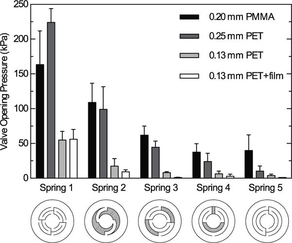
Valve opening pressures under forward pressure as a function of spring design (adapted from Nguyen et al.8) and material. Spring patterns are shown underneath their corresponding data and name designation. Experiments were performed with triplicate measurements from at least 6 independently constructed valves. Valves were considered open when pressurized air was seen to pass through the valve outlet into soapy water, creating small bubbles. No valves leaked under reverse pressure.
We also integrated check valves into machined valve housings. This approach is depicted in Fig. 1E–F. Using conventional machining, we created a cylindrical valve housing with a central inlet hole and an offset outlet hole. A countersunk region at the center of the housing made it easy to center the elastomer disc, while a small annular boss was preserved around the inlet hole to enhance sealing. In this case, the laser-cut orthoplanar spring was easy to place correctly into the valve because the housing’s sidewalls were already in place. The spring merely had to be dropped into place. Finally, a fluid-sealing plug was pressed into the valve housing over the top of the orthoplanar spring, pushing the spring’s perimeter flush against the base of the valve housing. Pre-stress was introduced into the spring due to the thickness of the elastomeric sealing pad, which rested against the top of the raised annular boss and stood proud of the valve housing floor. We were able to visualize the quality of the seal formed by pressing the elastomeric disc against the annular boss in machined valve housings using an optical microscope although similar visualization was not possible in laser-cut housings. While the surface of the silicone we used normally appears uneven and lumpy under magnification, the silicone pressed against the annular boss displays a smooth appearance, indicating that it has deformed to make a complete seal against the smooth PMMA valve housing (Fig. 2B). Here, controlling the depth of the press-fit plug’s central depression minimized the check valve’s dead volume.
While our valve design was inspired by past work,8,11 the valves we present here have a number of distinguishing features. For example, unlike most previously reported orthoplanar springs used in microfluidic check valves,8–10 the spring we incorporate is pre-stressed. This pre-stressed spring eliminates leaks by securely closing the valve inlet to reverse flow. An additional innovation was using two distinct materials to create the valves’ springs and sealing pads. This two-part design permits independent selection of the spring and sealing pad’s properties to match their intended use. As a result, the valve opening pressure can be adjusted by selecting materials with different elastic moduli or thickness, and the much softer elastomer pad can easily deform to effect a tight face seal, especially when used in conjunction with a raised annular boss. In previous descriptions of orthoplanar spring check valves, pre-stressed springs were made from a single material, SU8, that had to possess adequate stiffness to act as a spring yet still be soft enough to seal the valve inlet.8–11 This compromise precluded Smal et al. from implementing metal springs in leak-free, pre-stressed check valves.11 Our more versatile design enables pre-stressing of springs made from flat sheets of any flexible starting material. Previous orthoplanar spring check valves have been made from SU8,8,11 stainless steel,11 nickel,9 and parylene C.10 Here we present valves made from PET, PMMA, or both. Because we utilize thermoplastic materials, we can rapidly prototype mass-producible devices with integrated check valves using a CO2 laser cutter and expect similar valve performance from late-stage assemblies produced by conventional machining or injection molding. This is not the case with rotary multiport valves3 or overmolded cracking pressure valves,4 the properties of which cannot be replicated readily in low-volume lab prototypes. Moreover, springs providing different opening pressures may be incorporated into devices with identical valve housings, adding functionality without increasing device cost or complexity. These features could be of great value to point of care diagnostics developers who wish to modify valve parameters without avoid costly redesigns when scaling up production from early prototypes. Collectively, the innovations in our new check valve design make passive, normally closed check valves more robust and easier to incorporate into disposable, thermoplastic assays used at the point of care.
A two-part valve design admittedly comes with its own challenges. Unlike the spring valves of Nguyen et al.8 and Smal et al.,11 our spring valves require aligning two separate parts within the assembly. We mitigated the risk of poor alignment by removing static charge from components and designing the housing geometry to ensure concentric placement of the spring and elastomer disc (Figure 1E–F). Concentric alignment would become more challenging should the valves become smaller.
Valve performance and impact of valve design parameters on opening pressure
Our design allows for wide adjustability of opening pressure through the selection of orthoplanar spring pattern, spring material stiffness, and spring thickness. We demonstrate this in Fig. 3, which displays opening pressures for laser-cut and layer-by-layer assembled valves featuring different orthoplanar springs made from PMMA and PET materials. Nguyen et al. previously presented designs to create 6 orthoplanar springs with varying stiffness out of SU8 by photolithography.8 Here, we adapted the first 5 of those designs to the laser cutter and demonstrated that the spring pattern chosen for the valve can be used to dramatically tune the check valve’s opening pressure. For example, when cut from 0.25 mm PET, spring 1 opens at an average of 220 kPa, while spring 5 opens at around 13.8 kPa. This is accomplished by effectively adjusting the length of the beam connecting the perimeter of the spring to the spring’s center, which is in contact with the elastomeric sealing pad. The stiffness of the plastic used to create the spring also affects the valve opening pressure. For instance, most of the springs made from 0.2 mm PMMA open at higher pressures than springs made from the thicker 0.25 mm PET (which are even thicker along their edges due to the melt ridge described earlier). This is because the elastic modulus of PMMA is typically higher than that of PET materials. Finally, we demonstrated that the thickness of the PET used to create the orthoplanar springs could influence the valve opening pressure. The stiffness of a cantilever beam is known to be proportional to the beam’s moment of inertia. For a beam with a rectangular cross section, the moment of inertia is proportional to the cube of the thickness. Thus, thinner materials should make much more compliant springs and open at lower pressures. Indeed, we observed that springs made from 0.13 mm PET opened at much lower pressures than equivalent springs cut from 0.25 mm PET. With the thickness halved, one might expect an approximately 8-fold reduction in opening pressures. We observed a less dramatic drop in opening pressures, however, between 3-fold to 5-fold. This could be due in part to the dumbbell-shaped cross section of the PET spring arms. Using digital calipers, we determined that the thickness of the melt ridge was nearly double that of the base PET. We tested how significantly the melt ridge affected valve opening pressures by replicating the 0.13 mm PET valves using springs that were cut from a PET sheet covered with a protective cover layer that helped to spread heat away from the cut site and minimize melt ridge formation. As we show in Fig. 3, the PET + film springs open at lower pressures than springs with melt ridges for all spring patterns except the first.
Valve parameters with less impact on opening pressure included inlet hole diameter, elastomer stiffness (durometer), and elastomer thickness. Using the scheme presented in Fig. 1A–B, we tested valves with inlet holes ranging between 0.25 mm and 1.5 mm in diameter and observed little effect on valve opening pressure. It is possible that varying the inner diameter of the annular boss featured in either the laser-engraved or machined valve housings (Fig 1C–F) could influence valve opening pressure, but we believe altering spring design affords greater control. Additionally, we found that changing elastomer durometer from 10A to 30A had little to no effect on mean opening pressure, but did increase the variability of opening pressures. Increasing elastomer stiffness to 40A resulted in unacceptable opening pressure variability and poor leak performance under back pressure in laser-cut valves without an annular boss. In general, soft, easily deformable elastomer delivered the best leak-proof and consistent opening performance. For valves prepared with 10A silicone sealing pads, back pressure up to 275 kPa never resulted in leaks, and the contact adhesives used to assemble valve housings (Fig 1A–D) failed before the valve seal itself (machined housings, Fig 1E–F, did not delaminate or fail at any pressures tested). Finally, we found that increasing elastomer disc thickness, and thus the pre-stress in the spring, increased the valve opening pressure. Based on limited observations with three thicknesses of 10A durometer silicone, opening pressure increased approximately 160 Pa/μm of additional spring displacement (0.25 mm PET spring, spring type 1), making them quite tolerant to slight variations in silicone thickness. Valve types requiring precise compression of elastomers to function correctly may not be as robust, and often leaked or created blockages when we tried to incorporate them into our own laser-cut prototypes (data not shown).
Staged delivery of on-board reagents and finger-actuated pumping
On-board reagent storage, staged fluid delivery, fluid metering, and pumping are often enabled by single use valve-like features in hand-operated disposable diagnostics. For example, on-board reagent storage in many point of care diagnostic devices is accomplished with blister packs or frangible seals. Staged fluid delivery is often accomplished with capillary valves, which “burst” open when a triggering fluid flows past. While these features are elegant solutions to specific problems, they lack the full functionality provided by a normally closed passive check valve. For instance, blister packs cannot reseal after dispensing a portion of their contents, nor can they prevent downstream fluids from re-entering the breached blister. In addition, capillary burst valves generally cannot close once they have been triggered and do not guarantee one directional flow. In contrast to the frangible seals and capillary valves incorporated into rigid thermoplastic devices, check valves incorporated into hand-operated PDMS devices possess greater functionality.1,2 Here we demonstrate that orthoplanar spring check valves offer the full functionality of traditional check valves for reagent storage and isolation as well as pumping in thermoplastic devices.
We prepared finger-operated devices with a laser cutter that stage fluid delivery from on-board reagent storage reservoirs to a common expandable reservoir, as shown in Fig. 4A (multimedia view in Movie 1, device schematic in Fig. S1). Before actuation, the laser cut check valves kept the yellow and blue reagents (food coloring) in place in their storage reservoirs. Using a finger, we first pressed on the blue reservoir, sending blue food coloring into the common downstream chamber. The passive sealing action of the check valves prevented backflow into either the blue or yellow reagent reservoirs. Next, we dispensed a yellow food coloring into the common chamber by pressing on the yellow reservoir. The volume of yellow food coloring dispensed was smaller than that of blue food coloring due to the smaller size of its reagent reservoir. A similar approach might be used to accomplish volume metering with these valves. Despite the increased pressure in the common chamber, neither yellow nor blue food coloring moved back into the yellow or blue reservoirs. When we pressed repeatedly on the now swollen common chamber to mix the blue and yellow food coloring (making green), the valves entirely prevented backflow through the valves. In fact, we observed that the fairly strong cyanoacrylate adhesive holding the clear silicone to the PMMA chip base began to fail following aggressive mixing with a finger while the valves’ integrity and reagent reservoirs’ contents were unaffected (Fig. 4A, mixed). An important advantage of our check valve over frangible seals or capillary valves for dispensing on-board reagents is that the valves are self-sealing once fluid has been dispensed. Therefore, these check valves enable fluid delivery to pressurized chambers and staged reagent delivery without unwanted mixing. Unlike rotary multiport valves, no external actuation is required to achieve this isolation.3
FIG. 4.

A) Laser cut and engraved PMMA device with check valves demonstrating on-board storage of fluid reagents and finger-actuated, sequential delivery of different fluid volumes to a common mixing chamber. Check valves seal each reagent reservoir from the pressurized downstream mixing chamber (multimedia view). Scale bar = 1 cm; B) check valves enable finger-actuated pumping of air and fluid into a microfluidic frog throat (multimedia view). Air moves through the right nostril into the eyes, which are depressed to fill the throat with air. Scale bar = 2 cm. Abbreviations: V1 = valve 1, V2 = valve 2, E = elastomeric membrane.
We placed two check valves in series to create a finger-operated pump resembling a cartoon frog (Fig. 4B, multimedia view in Movie 2, device schematic in Fig. S2). Like a real frog, our device “breathed” in air through a “nostril” and used this air to pressurize a “throat”, which distended until it eventually popped. The pump consisted of an inlet hole (at valve 1), a deformable air chamber (the two eyes, covered with clear silicone and connected via channels cut in an adhesive layer) flanked by two laser-engraved check valves (valves 1 and 2), and a distensible air chamber covered in a soft grey silicone (the throat pouch). To operate the pump, we first pressed on the two eyes simultaneously, increasing pressure in the pumping chamber. Since valve 1 seals passively against backflow, air was pushed through valve 2 into the distensible air chamber. This gave the appearance of the frog inflating its throat. We then removed our fingers, allowing the tension in the clear silicone “eyes” to draw air into the pumping chamber through valve 1 (the right nostril). The inflated throat did not decrease in size, demonstrating that our check valves form gastight seals against reverse flow. After waiting a few seconds, we then pushed on the eyes again, further inflating the frog’s throat. We repeated this process until the soft silicone was completely transparent and stretched to over 500% strain based on curve length measured from side-view images. Shortly thereafter, the frog “croaked”—its silicone throat had ruptured. Although rather whimsical, with the “microfluidic frog” we demonstrated that laser-cut passive check valves can be arranged in a simple circuit to form a one-directional pump.
Application of valves to sealing a device for RT-LAMP detection of West Nile virus
One of our research interests is developing microfluidic systems for simplified detection of vector-borne disease in the environment or at the point of care. One approach has been to utilize isothermal nucleic acid amplification techniques such as RT-LAMP to detect RNA from viruses carried by mosquitoes.14–16 Throughout the United States, West Nile Virus (WNV) poses a significant health risk to people, livestock, and wildlife, with over 2000 confirmed human cases in 2015.17 In the laboratory, we routinely detect WNV RNA extracted from field-caught mosquitoes, or even intact (not extracted) WNV by mixing a sample containing virus (or viral RNA) with a standard reagent mix for reverse transcription loop mediated isothermal amplification (RT-LAMP) and incubating the mixture in polypropylene tubes at a constant temperature of 65°C for 30 minutes. The resulting amplification of target nucleic acids results in a bright fluorescent signal when the reaction is cooled back to room temperature, using a recently developed detection chemistry called QUASR (quenching of unincorporated amplification signal reporters).14 Negative reactions remain dark. Manually conducted QUASR RT-LAMP requires pipetting a defined volume of reagents into the polypropylene tube and then sealing the tube with a snap cap to prevent sample evaporation. Furthermore, the sample is typically heated both from below to maintain constant reaction temperature and from above to prevent evaporation and condensation of the sample onto the lid. As an alternative to laboratory-based detection, we have implemented microfluidic assays to automate QUASR RT-LAMP detection of WNV in a prototype field-deployable chip.
We prototyped chips from 2 layers of laser-etched PMMA and a single layer of laser-cut acrylic adhesive, and used them to detect WNV RNA with isothermal amplification (Fig. 5, device schematic in Fig. S3). Nath et al. previously reported laser-cut microfluidic chips assembled with pressure sensitive adhesives, including chips that successfully conduct polymerase chain reaction.12,13 Nath et al. showed that leachate from laser cut acrylic adhesives inhibited PCR. We found that the enzymes used in RT-LAMP tolerate acrylic adhesives, and that QUASR provides a reliable endpoint signal for the reaction (in our experience, nonspecific calcein and SYTO dye detection methods failed in the presence of acrylic adhesives). The devices were pre-filled with dried reagents, including on-board positive and negative controls. Dry-stabilized QUASR RT-LAMP reagents showed minimal loss in activity in accelerated aging tests at sustained temperatures of 45°C for at least 2 weeks, or 60°C for one week (data not shown). Other reports have demonstrated similarly stabilized LAMP reagents by air drying with trehalose or lyophilisation.18,19 We added a rehydration buffer and target WNV RNA to an integrated polypropylene tube sample holder, and replaced the tube’s cap, which were modified to have a finger-actuated pump (the bulb from a squeeze pipette). We filled the chip by squeezing the pipette bulb, which causes the channels to fully fill with around 200 kPa of applied pressure. A check valve with a laser-engraved headspace sealed off the reaction channels after filling. As expected for QUASR, only the lane with no quenching probe fluoresced when rehydrated (Fig. 5C). Chips were then placed on a heat plate at 65°C for 30 minutes for nucleic acid amplification to occur. Upon heating above the melting temperature of the quenching probe, all channels fluoresced red under green illumination (Fig. 5C). Upon cooling to room temperature, an LED and camera fitted with excitation and emission filters were used to visualize positive amplification (positive reactions remain bright when cool). These devices accurately and reliably detected WNV using endpoint detection, and prevented contamination of the lab space with amplicon (Fig. 5). The use of the passive, normally closed check valves enabled a single actuation step (pressurizing the sample fluid) to fill the chip, seal the chip, and minimize evaporation under heating.
FIG. 5.

Valves applied to WNV detection. A) Laser cut prototype device with integrated sample holder and squeeze pipette bulb cap, image taken in room light after running QUASR RT-LAMP. B) The same device illuminated with a green LED flashlight and viewed through a plastic filter. The first two channels are positive, and the last two are negative for WNV. C) Images of the chip taken during different stages of use: dry, filled with rehydration buffer and sample, heated during the RT-LAMP reaction, and cooled to 20°C after 30 min at 65°C. The channels (from bottom to top) include a no quenching probe positive control (NQ PC), a pre-dried 100 PFU equivalent of RNA positive control (100 PFU PC), a test channel, in this case with 100 PFU per 10 μL of RNA, and a no enzyme control (NEC). D) Fluorescence of each reaction channel normalized to the signal in the NQ PC channel. Data represent mean and standard deviation for 3 independent devices (n = 3 for NQ PC, 100 PFU PC, and NEC; n = 2 for 100 PFU test; n = 1 for no template (NT) test).
Conclusions
We have presented designs for normally closed, passive check valves that are “native” to laser cutter prototyping, but can be seamlessly integrated into machined chips and should integrate identically into injection molded parts without having to redesign the system around a new type of valve. The check valves employ a pre-stressed orthoplanar spring to press a soft elastomeric sealing pad against an annular sealing surface. The design is inherently adaptable, supporting multiple spring materials and offering adjustable opening pressure by simply modifying orthoplanar spring pattern. These check valves provide new opportunities to design staged reagent delivery and functionality into laser-cut prototype point-of-care diagnostic devices as well as commercial stage diagnostics.
Supplementary Material
Acknowledgments
We would like to acknowledge Lark Coffey and Sarah Wheeler at University of California-Davis Center for Vectorborne Diseases for samples of WNV RNA. Funding for this project was provided by Defense Threat Reduction Agency (DTRA), contract DTRA1002715801; Sandia National Laboratories Laboratory-Directed Research and Development (Project 173111); and National Institutes of Health (NIAID
Grant 5R21AI120973-02).
Footnotes
Sponsor-required statement: Approved for public release, distribution is unlimited.
Electronic Supplementary Information (ESI) available: [videos of staged reagent delivery and pumping applications, detailed methods for chip assembly, molecular assay primer set, and drawings of chip designs]. See DOI: 10.1039/x0xx00000x
References
- 1.Li W, Chen T, Chen Z, Fei P, Yu Z, Pang Y, Huang Y. Lab Chip. 2012;12:1587–5. doi: 10.1039/c2lc40125h. [DOI] [PubMed] [Google Scholar]
- 2.Xu K, Begley MR, Landers JP. Lab Chip. 2015;15:867–876. doi: 10.1039/c4lc01319k. [DOI] [PubMed] [Google Scholar]
- 3.Becker H, Klemm R, Stewart R, Gärtner C. 16th International Conference on Miniaturized Systems for Chemistry and Life Sciences, Proc. MicroTAS; Okinawa. 2012. [Google Scholar]
- 4.Ceriani D. presented in part at Lab-on-a-chip microfluidics microarrays world congress; San Diego. September, 2015. [Google Scholar]
- 5.Al-Faqheri W, Ibrahim F, Thio THG, Aeinehvand MM, Arof H, Madou M. Sensors & Actuators: A Physical. 2015;222:245–254. [Google Scholar]
- 6.Hickerson AI, Lu HW, Roskos K, Carey T, Niemz A. Sensors & Actuators: A Physical. 2013;203:76–81. doi: 10.1016/j.sna.2013.08.016. [DOI] [PMC free article] [PubMed] [Google Scholar]
- 7.Snakenborg D, Klank H, Kutter JP. Microfluidics and Nanofluidics. 2010;10:381–388. [Google Scholar]
- 8.Nguyen NT, Truong TQ, Wong KK, Ho SS, Low CLN. J Micromech Microeng. 2004;14:69–75. [Google Scholar]
- 9.Cheng CH, Tseng YP. Microsyst Technol. 2013;19:1707–1715. [Google Scholar]
- 10.Fong J, Xiao Z, Takahata K. Lab Chip. 2015;15:1050–1058. doi: 10.1039/c4lc01290a. [DOI] [PubMed] [Google Scholar]
- 11.Smal O, Dehez B, Raucent B, De Volder M, Peirs J, Reynaerts D, Ceyssens F, Coosemans J, Puers R. J Micro-Nano Mech. 2008;4:131–143. [Google Scholar]
- 12.Nath P, Fung D, Kunde YA, Zeytun A, Branch B, Goddard G. Lab Chip. 2010;10:2286–2291. doi: 10.1039/c002457k. [DOI] [PubMed] [Google Scholar]
- 13.Nath P, Maity TS, Pettersson F, Resnick J, Kunde Y, Kraus N, Castano N. Microsystem Tech. 2013;20:1187–1193. [Google Scholar]
- 14.Ball C, Light Y, Koh C, Wheeler S, Coffey L, Meagher R. Anal Chem. 2016;88:3562–3568. doi: 10.1021/acs.analchem.5b04054. [DOI] [PubMed] [Google Scholar]
- 15.Parida M, Posadas G, Inoue S, Hasebe F, Morita K. Journal of Clinical Microbiology. 2004;42:257–263. doi: 10.1128/JCM.42.1.257-263.2004. [DOI] [PMC free article] [PubMed] [Google Scholar]
- 16.Wheeler S, Ball C, Langevin S, Fang Y, Coffey L, Meagher R. PLOS ONE. 2016;11:e0147962–17. doi: 10.1371/journal.pone.0147962. [DOI] [PMC free article] [PubMed] [Google Scholar]
- 17.CDC West Nile virus. http://www.cdc.gov/westnile/statsmaps/preliminarymapsdata/index.html, (accessed August 2016)
- 18.Hayashida K, Kajino K, Hachaambwa L, Namangala B, Sugimoto C. PLoS Negl Trop Dis. 2015;9:e0003578. doi: 10.1371/journal.pntd.0003578. [DOI] [PMC free article] [PubMed] [Google Scholar]
- 19.Chen HW, Ching WM. J Vis Exp. 2016;110:e53839. doi: 10.3791/53839. [DOI] [PMC free article] [PubMed] [Google Scholar]
Associated Data
This section collects any data citations, data availability statements, or supplementary materials included in this article.