Abstract
Progress in the electrospinning techniques has brought new methods for the production and construction of various nanofibrous assemblies. The parameters affecting electrospinning include electrical charges on the emerging jet, charge density and removal, as well as effects of external perturbations. The solvent and the method of fiber collection also affect the construction of the final nanofibrous architecture. Various techniques of yarn spinning using solid and liquid surfaces as well as surface-free collection are described and compared in this review. Recent advances allow production of 3D nanofibrous scaffolds with a desired microstructure. In the area of tissue regeneration and bioengineering, 3D scaffolds should bring nanofibrous technology closer to clinical applications. There is sufficient understanding of the electrospinning process and experimental results to suggest that precision electrospinning is a real possibility.
Keywords: nanofiber, 3D structure, mass production, hierarchical organization
Introduction
Technological advances over the last few decades have resulted in the realization of several competing processes for fabricating nanometer-size objects. The development of nanolithography through the improvement of traditional microfabrication methods has enabled the construction of precise nanocircuits, while melt blowing can be used to mass-produce nanofibers. Although these technologies are excellent in their specific application domains, electrospinning has emerged as a popular nanotechnology since the late 1990 s owing to the ease of fabricating nanofibers from a wide selection of materials. Researchers have explored the usage of electrospun nonwoven membranes in applications such as tissue engineering, energy, water filtration, biotechnology and sensors [1]. In particular, this random mesh of nanofibers is suitable for air filtration because many commercial microfibrous membranes are already in nonwoven forms. In tissue engineering, early studies were mainly on interactions between cells and nanofibers, and little attention was paid to the structure of the substrate. Preliminary investigations into using nanofibers for other applications were not concerned with fiber arrangements. Nevertheless, it soon became apparent that ordered nanofibrous structures could outperform disordered ones. For example, cells cultured on aligned nanofibers become aligned in the direction of the fibers [2]. Other researchers are also beginning to look into fabricating hierarchically organized and multifunctional nanofibrous structures [3].
As new applications are found and new materials are electrospun into nanofibers, the need to understand current developments in nanofibrous structures to realize their potential has become increasingly important. Most research on electrospun nanofibers and industrial applications has been restricted to nonwoven membranes; however, this technology is leading to the generation of more elaborate structures. Understanding the electric field profile and its effect on the electrospinning jet has resulted in new ways of ordering nanofibers. Mechanical methods, such as those using rotating drums, disks and moving platform collectors, and simple manipulation of the electric field have been successfully used to fabricate membranes with ordered nanofibers. Details of these methods have been covered in our previous review [4]. Recent studies of this technology have led to greater understanding and emphasis on fabricating commercially viable and more ordered structures. Yarns and three-dimensional (3D) scaffolds have been constructed using electrospinning. A few companies such as Donaldson and Finetex have been using electrospun nanofibers in their products but much of the science and technology behind their ability to mass-produce electrospun nanofibers remains a trade secret. The difficulty of mass-producing nanofibers by electrospinning becomes apparent from reading academic reports. Air filtration is one of the early applications of this technology as it only requires a thin nanofibrous layer (2 to 3 nanofibers thick) to achieve a significant improvement in performance and justify the relatively high production cost. More efficient electrospinning setups and fiber organization are needed to enhance the productivity of this technology, which may potentially rival conventional nanolithography owing to the steady improvements in the production rate and the control of the electrospinning jet to obtain ordered structures.
In this review, we focus on recent developments in electrospinning designs and nanofibrous assemblies, in particular, the mass production of nanofibers, nanofibrous yarn fabrication, 3D scaffold fabrication and precision electrospinning. Some basic parameters that govern electrospinning design and the fabrication of nanofibrous assemblies are also introduced.
Electrical charges
Electrospinning is based on inducing static electrical charges on the molecules of a solution at such a density that the self-repulsion of the charges causes the liquid to stretch into a fiber in an electric field [5]. Provided there is no breakage in the stretched solution, a single strand of continuous fiber is formed upon solvent evaporation. When a high voltage is applied to the solution, the ohmic current distributes the charges throughout the molecules. As the solution is ejected from the spinneret tip, the ohmic current transits to a predominantly convective current [6]. The charges are transported from the electrospinning tip to the target through the deposition of the fiber [7]. The current stops oscillating when the deposition becomes stable. This can be used to monitor the spinning process [8]. The electrical charges used for electrospinning can be positive, negative or both (alternating current) [9–12]. Although most reported electrospinning experiments were carried out using a positive potential, it has been shown that a negative potential produces nanofibers with a narrower diameter distribution. This was explained by the fact that electrons can be dispersed more rapidly and uniformly than the much heavier protons [13].
Solution delivery design (overcoming surface tension)
In a typical electrospinning setup, a high-voltage source is connected to a metallic needle, which is attached to a solution reservoir. The needle has a relatively small orifice that concentrates the electric charge density on a small pendant drop of solution [14]. Although a metallic spinneret such as a needle is convenient for the application of charge to the solution, the process also works if a high voltage is applied to the solution using a dedicated electrode with a nonconducting spinneret [14]. A porous cylinder [15] has also been used for electrospinning, and it is possible to induce charges on a free solution droplet without direct contact to form a fiber [13, 16, 17].
The theoretical modeling of a viscous leaky dielectric solution subjected to a critical voltage showed that it becomes unstable in an electric field when the surface tension can no longer maintain its static equilibrium [18]. At this voltage, protrusions form on the solution surface and jets of solution are ejected. Any perturbation or nonuniformity on the solution surface will concentrate charges in regions with higher curvature. If the curvature is sufficiently large for the potential difference between such a region and the collector to reach a critical value, the solution erupts from the surface and accelerates towards the collector [19]. This has given rise to numerous designs in which drums [20, 21], spikes [22], ridges [23] and disks [21] have been used to dispense the solution for electrospinning. He et al [24] demonstrated that bubbling air in the solution and the subsequent disruption on the solution surface can initiate electrospinning at a reduced voltage.
Charge density on electrospinning jet
The voltage supplied to the solution determines the charge density on the electrospinning jet—when the charge density is too high, the jet becomes highly unstable. Conversely, when the charge density is too low, the solution drips. Thus, there is an optimum voltage for stable spinning without any surface perturbations in the conical base region of the solution [25]. At the initiation of electrospinning, the interaction between the electric field and the surface charges on the jet causes the liquid to accelerate towards the collector. Disregarding the viscosity and stiffness of the solution, a higher charge density on the jet causes greater instability [26, 27]. In a perfect dielectric jet, the nonuniformity in the radius of the jet along its length results in surface charges accumulating on the protruding regions. The self-repulsion of the charges tends to destabilize the jet, while tangential stress acting parallel to the flow tends to stabilize it. At a high charge density, the self-repulsion exceeds the stabilizing tangential stress resulting in bending instability [28]. The bending instability may become so chaotic that loops of single jet merge into a cross-linked network. The series of close loops may constrain the motion of the electrospinning jet and form a fluffy cylindrical column with a diameter of a few millimeters [29].
As the voltage increases, the increased charge density reduces the fiber diameter as the jet becomes stretched under a greater force; however, above an optimal voltage, the diameter starts to increase [30]. This has been attributed to more material being drawn from the Taylor cone under increasing field strength and number of charges on the jet [31].
Electrical discharge/neutralization
In electrospinning, an electrically earthed collector is often used to collect the nanofibers. However, since the deposited nanofibers are typically nonconductive, residual charges build up as the nanofiber layer becomes thicker. This has several side effects such as creating a repulsive force which diverts the jet to other regions, nonuniform packing density, adhesion between layers of nanofibers and disruption of the nanofiber organization in cases where ordered patterns are desirable. A deionizer is an effective way of quickly removing charges from the electrospinning jet. However, it must be placed at an appropriate distance so that the charges are removed only when the fibers are sufficiently stretched and are relatively dry. Otherwise, beaded fibers may form if the electrospinning jet is discharged prematurely [32]. Furthermore, a discharged electrospinning jet cannot be controlled using auxiliary electrodes.
External effects
External forces on the spinning jet
Electrical force
The effect of the electric field profile around the electrospinning jet has been studied by many researchers. The charges on the electrospinning jet allow its path to be altered by an electric field. In a basic electrospinning setup, the polarity and strength of the voltage applied to both the spinneret and the collector can be varied. In more complex setups, auxiliary electrodes can be added, which have been used to control the deposition location and area [33] of the electrospun fiber, aligning nanofibers [34, 35] and forming simple patterns [36]. The auxiliary electrodes can be divided into the base electrode, steering electrodes, focusing electrodes, the collector and guiding electrodes as shown in figure 1.
Figure 1.
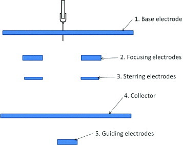
Auxiliary electrodes for altering the electric field profile.
The base electrode is usually a conductive plate, which creates a uniform background electric field between the spinneret and the collector; without a base electrode, the electric field can be affected by surrounding objects. The chaotic motion of the electrospinning jet may also veer off owing to the effect of this electric field. Yang et al [26] showed that the addition of a base electrode resulted in fibers with smaller diameters and a longer stable jet. An important consideration when a base electrode is used is the protrusion of the spinneret tip from the base electrode. If the spinneret tip is retracted into the base electrode, spinning may not occur at the same voltage. In contrast, when a conducting spinneret tip protrudes about 1 cm from the base electrode, the fringe field at the spinneret tip may locally exceed the average field between the base electrode and the collector, and spinning will be initiated [37]. A disadvantage of using a base electrode is that a higher applied voltage is required to initiate spinning [26].
The function of the focusing electrodes is to damp the chaotic motion of the electrospinning jet so that fiber deposition is more localized. They can be shaped as a ring, cylinder or cone and are usually placed close to the spinneret tip so that damping is more effective [38–40]. Multiple focusing electrodes have also been used to reduce the spread of the fiber [33]. As a type of focusing electrode, Salim et al applied a gold-coated polydimethylsiloxane mask with holes 400 μm in diameter to repel fibers from its surface and direct them through the holes and onto a collecting substrate. The authors were able to collect patches of randomly oriented nanofibers on the substrate and restrict the deposition area of each nanofiber patch to a circle with diameter less than 200 μm [41]. Using the ability to focus the electrospinning deposition onto a small spot, patterns composed of randomly ordered nanofibers can be fabricated by moving the collector plate [38]. However, as the electrospinning jet moves at a high speed, it may not be realistic to match the speed of the collector to that of the electrospinning jet to form ordered nanofiber patterns. Therefore, an alternative method is to use steering electrodes to direct the deposition of nanofibers.
Depending on the complexity of the nanofiber pattern to be fabricated, steering electrodes may consist of two or more electrodes [36, 39, 42]. A single parallel electrode system allows control only along a single axis and has been successfully used to fabricate aligned nanofibers [42]. However, multiple pairs of electrodes are required to form more complex patterns. Only simple patterns, such as a square made of nanofibers, have been fabricated using steering electrodes thus far [36]. Nevertheless, more complex patterns may be possible using the above concept.
The collector itself can play an important role in the deposition of nanofibers. Through the use of a knife-edge disk collector, Theron et al [43] demonstrated that a grounded knife-edge guides the electrospinning jet toward it. Other researchers have used collectors with grids [44–47] or charged needles [48] to create patterned nanofibrous membranes as shown in figure 2. These patterned nanofibrous meshes consist of regions of high fiber density; the potential and fiber density were lower in insulated regions.
Figure 2.
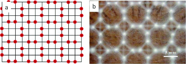
Collector grids made of selectively charged needles showing (a) the location of charged needles and (b) the corresponding nanofiber deposition. (Reproduced with permission from [48] © 2009 IOP Publishing.)
The positioning of the collector also affects fiber deposition. When two conducting collectors are placed in parallel as shown in figure 3, it is possible to collect highly aligned nanofibers. The arrangement of parallel electrode collectors with a gap or insulating section between the electrodes creates an electric field profile that forces the charged nanofiber to span the gap [35]. Li et al demonstrated that there is a maximum gap size above which the nanofibers are broken (> 1 cm for nanofibers thinner than 150 nm). They hypothesized that this was due to the inability of a nanofiber to support its own weight beyond a certain length [35]. Beachley and Wen showed that increasing the polymer solution concentration and the size of the plate collector allowed the gap [49] to be increased to 35–50 cm for aligned fibers with a diameter of 350 nm to 1 μm. Liu and Dzenis demonstrated that increasing the gap distance improves the alignment of the nanofibers. Using polyethylene oxide solution, aligned fibers were obtained with a gap of 18 cm [34]. Ishii et al used this method to control the number of nanofibers across plates by switching the polarity of the charges on them. Assuming that the electrospinning jet was positively charged, one of the plates was first given a negative charge so that nanofibers were deposited on it. The other plate was then charged negatively to lay a single nanofiber strand across the gap to the other plate. The number of nanofibers spanning the gap could be controlled by varying the number of times the polarity was switched [50].
Figure 3.
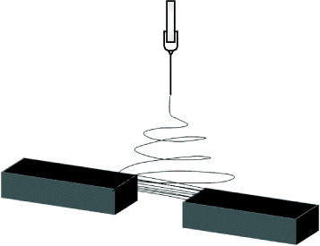
Deposition of aligned nanofibers over a parallel electrode collector system.
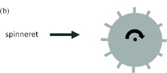
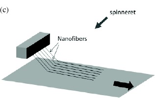
The success and simplicity of using the parallel electrode collector principle has generated various modifications to obtain different nanofiber assemblies. Arrays of nanofibers have been fabricated by employing multiple pairs of electrodes [51]. A pair of aligned blades allows nanofibers to form aligned bundles across the gap between the blades [52]. Depositing the fibers in a gap between two ring collectors [53] or a ring collector and a needle [54], and then applying a twist to one of the collectors while keeping the other end stationary gives rise to a twisted nanofiber bundle. However, there are still various critical shortcomings in this setup. The build-up of residual charges as nanofibers are deposited across the gap reduces the attractive strength of the electrodes and causes fiber misalignment [34, 55], thus limiting the thickness of aligned nanofibers that can be obtained. Another significant drawback is that most nanofibers are randomly deposited on the electrode surface instead of spanning the gap. Thus, the productivity of this method is very low compared with other methods of fabricating aligned nanofibrous membranes. The attempts to increase the productivity of the parallel electrode system to obtain aligned nanofibers are summarized in table 1. When parallel electrodes are rotated as in cases (a and b) in table 1, the spacing between the electrodes causes air turbulence at high rotation speed, which disrupts the fiber deposition. This contrasts with mechanical drawing methods for achieving fiber alignment where a higher rotation speed is preferred. Since steering electrodes and a charged collector are both effective in directing the deposition of electrospun nanofibers, Acharya et al [42] have demonstrated that the combination of both techniques results in fibers with much better alignment.
Table 1.
Electrospinning setups based on parallel electrode collector principle to increase aligned fiber productivity.
 |
Multiple parallel electrodes used to collect |
| aligned nanofibers [55]. | |
 |
Multiple parallel electrodes used to collect |
| aligned nanofibers [56]. | |
 |
A dual collector system with a stationary |
| electrode placed above a moving belt causes | |
| fibers to align themselves between the top | |
| electrode and the moving belt below. As the belt | |
| moves, the nanofibers are pulled off the electrode | |
| above and are aligned on the belt below [57]. |
The electrospinning jet is sensitive to small differences in the electric field, and a wire placed below a glass slide has been shown to attract significantly more nanofibers onto the glass surface directly above the wire [4]. Therefore, a guiding electrode may be employed below the collector to direct the motion of the electrospinning jet. Teo et al [58] demonstrated that through the use of a knife-edge guiding electrode, the electrospinning jet can be directed to form aligned nanofibers at a desired angle on a tube. A guiding electrode in the form of a sharp tip has also been successfully used to create a nanofibrous grid [59–61]. Wu et al used a combination of like- and oppositely charged guiding electrodes behind a rotating rod to guide the deposition of nanofibers within a narrow band. The presence of multiple guiding electrodes also enhanced fiber alignment compared to when a single guiding electrode was used to attract the electrospinning jet [62].
Magnetic field
Theoretically, magnetic field can affect the spinning jet. Wu et al [63] suggested that the current carried on the jet as it travels in a spiral motion in a magnetic field creates a force towards the initial equilibrium point, thereby reducing the radius of the spiral; however, this has not been verified experimentally. Nevertheless, Ajao et al demonstrated fiber alignment on one face of a box made from silicon wafers with a cylindrical magnet inside. As shown in figure 4, the nanofibers were aligned in the direction of the electrospinning jet on the x–z-plane while nanofibers on all other faces were randomly aligned. It was suggested that this was due to the interaction of the electrospinning jet current in the y–z-plane, the magnetic field line along the y-axis caused a resultant force on the nanofibers in the x-direction [64].
Figure 4.
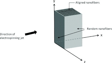
Cylindrical magnet boxed in silicon wafers. Aligned nanofibers are deposited on the top face of the box as shown in the figure. Random fibers covered all other faces of the box.
Gas-assisted effect
In some cases, electric charges alone may be insufficient to stretch the solution to form fibers. This may be due to the high viscosity and/or high surface tension of the solution. If volatile solvents are used, exposure to the environment and rapid evaporation of the solvent may render the solution unspinnable [65]. Thus, to facilitate the electrospinning process, a gas jacket that blows and exerts a stretching force on the solution can be applied at the spinneret tip as shown in figure 5. Um et al. used a gas jacket to electrospin hyaluronic acid that has a very high viscosity. Fiber fabrication can be improved by using a heated gas, as the higher temperature reduces the viscosity of the solution [66]. To electrospin solutions requiring a high temperature, such as ultrahigh-molecular-weight polyethylene solution, a heated gas jacket may stabilize the solution at the tip of the spinneret and facilitate the process [67].
Figure 5.
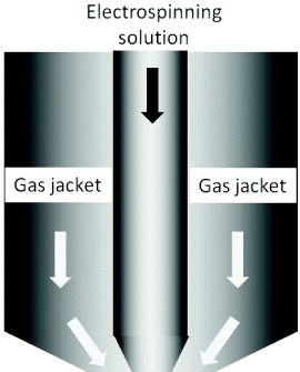
Design of spinneret for gas-jacket-assisted electrospinning.
Blowing a gas on the electrospinning jet can also be used to alter the nanofiber deposition. Varesano et al used the setup shown in figure 6 to disrupt the motion of the electrospinning jet by creating an air vortex where the spinning was carried out. As nanofibers are very light, they were transported by the air vortex and deposited as crimped fibers [68].
Figure 6.

Gas-assisted electrospinning to fabricate crimped fibers. Schematic drawings of setup from (a) side view and (b) top view. (c) Crimped nanofibers fabricated using the setup compared with (d) straight fibers fabricated using the conventional spinning setup. (Reproduced with permission from [68] ©2010 Elsevier.)
Solution and materials properties
Solution properties have been investigated as a means of controlling fiber characteristics such as diameter and morphology. However, this is one of the least explored parameters in the construction of nanofibrous assemblies. In addition to the electric field, it is also important to consider how solution and material properties may affect the assembly of more complicated nanostructures. The use of a solvent, polymer and/or additives with higher conductivity invariably affects the bending instability of the electrospinning jet. The addition of single-wall carbon nanotubes or salt added into the solution has been shown to create a more chaotic jet motion [29], thus encouraging the formation of nanofibrous tufts in mid-air, which can be drawn into a yarn [79, 88]. Similarly, loosely formed fibers on a solid substrate may also facilitate the drawing of fibers into yarns owing to the presence of high static charges [77]. Okuzaki et al reported the observation of bundles vertically oriented from the solid collector towards the spinneret. They attributed this to the ionic conduction of poly(p-xylenetetrahydrothiophenium chloride) used in the experiment [89].
Mass production
Electrospinning has been used for decades in the production of nonwoven nanofibers although it has not been widely adopted. This is probably due to its low production rate compared to other spinning techniques yielding larger diameter fibers. After the development of laboratory setups for various electrospun nanofibrous assemblies and ordered structures, the next challenge is to reproduce them at an industrial scale. Given the advantages of the high surface area of nanofibers for various applications, there is huge interest in nanofiber production at a commercial scale. Important criteria for determining the rate of fiber production include (i) concentration, (ii) the volume of solution forming spinning jet and (iii) the density of spinning jets.
The concentration of the solution determines the mass of fibers that can be produced per spinning jet. Since a higher concentration of polymer in the solution translates into greater output, some researchers used a melted polymer for electrospinning [90, 91]. However, as with spinning a high-concentration solution, the difficulty with using high- viscosity solutions is in stretching them into nanometer- diameter fibers. Heating the solution can reduce the viscosity, although above an optimum temperature, the increased rate of solvent evaporation may increase the viscosity [92]. It has been suggested that the application of vibration technology would lower the viscosity and thus improve electrospinning [93].
At a particular solution feed rate, not all the solution can be electrospun into fibers. Excess solution that is extruded but does not take part in the spinning will either coagulate at the spinneret tip or drip onto the collector. Therefore, it is important to consider the volume of solution that forms the spinning jet. Increasing the solution feed rate should be complemented by increasing the electric field strength through a higher applied voltage [94, 95] or shortening the distance between the spinneret tip and the collector [95]. Above a critical field strength, the mass flow rate of the solution or the volume of solution taking part in the spinning from the Taylor cone will increase [95, 96]. Alternatively, a solvent with higher conductivity may be used [97] or salt may be added to the spinning solution [98]. However, a solution with high electrical conductivity may cause the electrospun fibers to self-bundle and bridge the space between the static collector and the spinneret [95]. Fortunately, this can be easily resolved by using a moving collector.
Figure 7.
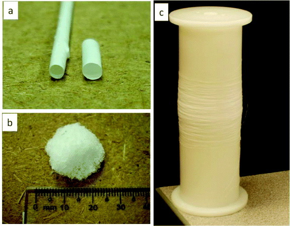
Various nanofibrous structures: (a) tubular structure, (b) 3D scaffold and (c) continuous nanofibrous yarn that can be fabricated through modification of the collection technique.
The density of spinning jets refers to the number of spinning jets per unit area. In conventional spinning, this density is limited by the number of orifices that can be forced in the spinneret. In electrospinning, there is a limit to the number of orifices that can be placed in a given space, which is imposed by the bending instability of the electrified jet. When multiple orifices are used, the electrospinning jets repel each other increasing the distance between the deposited fibers [99]. The situation worsens when orifices are placed closed together in a square grid configuration. The fringe electric field from the surrounding orifices interferes with the electric field at the central orifice and reduces the spinning ability. Wet fibers are deposited from the central orifice while the fibers spun from the orifices at the perimeter are dry [100].
In addition to forming a single jet to enable spinning from a single spinneret, it is possible to have multiple jets from a single spinneret [12, 101–103]. This may arise from increasing the voltage [98, 104] or from partial clogging of the Taylor cone [105]. Other forms of spinneret systems such as feeding the solution through a porous cylinder [15] and a conical wire coil [106] have been used to increase the spinning density. Moving beyond the constraint of using a nozzle or orifice to dispense the solution for spinning, a free solution surface has been developed to increase production. Some researchers have used spikes in the solution [22] or have blown bubbles into the solution [24, 107] to disrupt the solution surface, so that electrospinning jets can erupt from it. Another method of concentrating charges for electrospinning is to use a rotating disk that dipped into a solution bath with the electrospinning jet coming off from the edges of the disk [21]. If a sufficient voltage is applied, a rotating drum can be used instead of a disk to increase the area from which electrospinning jets can erupt [20, 21]. The advantage of this method is that the jets self-adjust the spacing between them [23] thus maximizing their density. An industrial setup based on this principle has been used by Elmarco s.r.o. in their nanofiber mass production equipment. Generally, nozzle and free-surface electrospinning or bath spinning are the most commonly employed techniques in the mass production of nanofibers by electrospinning, and table 2 briefly summarizes their advantages and disadvantages. Nozzle spinning is suitable for users who require nanofiber samples with various morphologies and composed of different materials. Free-surface electrospinning is recommended for simple repetitive spinning. Although nozzle spinning has the advantage of material selectivity and control of the fiber morphology, mass production with multiple needle nozzles still presents some fundamental challenges. To take full advantage of electrospinning, new spinneret systems based on nozzle spinning should be developed. Using a novel concept, Karpov Institute of Physical Chemistry created multiple solution-spinning jets by using a swirling air jet to break up the solution discharged by a capillary into multiple droplets. These droplets form individual jets under the affect of a high voltage. More details of their industrial process can be found in [108].
Table 2.
Comparison between nozzle electrospinning and free-surface electrospinning.
| Process | Advantages | Disadvantages |
|---|---|---|
| Nozzle | • Spinning solution with a wide range of viscosity | • Electrical field interference between nozzles |
| electrospinning | • Spinning at relatively low voltage | • Difficult to maintain (cleaning of nozzle) |
| • Collector can be placed in any direction relative to the nozzle | • Difficult to maintain a uniform feed rate through each orifice | |
| • Fabrication of fibers with various configurations (e.g. core-sheath, multicomponent and hollow fibers) | ||
| • Easy to translate experimental data from spinning with a single needle nozzle | ||
| Free-surface | • Easy maintenance | • Very high voltage required |
| electrospinning | • Easy to provide sufficient solution | • Difficult to maintain consistent solution viscosity owing to solvent evaporation |
Figure 8.
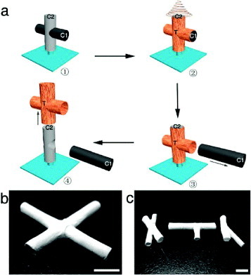
(a) Schematic demonstrating the process for fabricating multiple interconnecting tubes (C1, removable collector; C2, base collector; T, tubes with coated nanofibers). (b) X-junction tube and (c) various tubular structures (scale bar = 5 mm). (Reproduced with permission from [47] © 2010 American Chemical Society.)
Regarding the fiber spinning speed, electrospinning is comparable to traditional dry spinning (5 ms−1) [109, 110]. The velocity of an electrospinning jet has been estimated using a moving substrate and high-speed camera to be about 1–15 ms−1 [29, 62, 111, 112]. Although direct measurement of the fluid velocity at the tip of the nozzle using a high-speed camera has been reported, this velocity is only partly relevant to fiber productivity [101, 113]. Using laser Doppler velocimetry, Buer et al showed that the velocity of polyacrylonitrile in dimethylformamide is 10 ms−1 at a distance of 20 mm from the Taylor cone apex and 15 ms−1 at a distance of 80 mm [114]. Estimates of the electrospinning velocity based on the mass of the collected nanofibers range from 100 ms−1 to an astonishing 1000 ms−1 [108, 115–117]. Such a high value probably results from the splitting of the electrospinning jet [12, 118] or multiple electrospinning jets from the spinneret [12, 101–103, 105, 119]. Unfortunately, despite the relatively high drawing speed of nanofibers in the electrospinning process, there is a limit to the number of nozzles per unit area owing to the electric field interference between them. In terms of tex or denier, the production rate is also very low as nanofibers are intrinsically much lighter than larger-diameter fibers.
Table 3 summarizes representative techniques for the mass production of fibers by electrospinning. It is difficult to compare their productivity based on official information. The size of equipment, particularly the spinneret and the spinning volume per time, and the unit cost of samples are necessary to evaluate the productivity; unfortunately, this information is unavailable. For example, the productivity of needle-nozzle spinning increases with the number of needle-nozzles, but so does the space occupied by the nozzles. In addition to productivity, the cost of supplying more charges and the risk of electric discharge are higher for spinning at a high voltage.
Table 3.
Summary of nanofiber mass production setups∗.
| Applicable | Voltage of | ||||||||||
|---|---|---|---|---|---|---|---|---|---|---|---|
| Jet | Spinning | Product | Size of | substrate | power | Fiber | |||||
| Organization | Processing | generator | condition | name | equipmet | width (mm) | supply | Productivity | Material | diameter | Notes |
| Equipment | |||||||||||
| Elmarco s.r.o. | Bath spinning | Rotating cylinder | Solution spinning | NS Pilot Line 500 | 1700W 2200L | ∼ 600 | +80–60 kV | ∼3 g min−1 | PVA | 400 nm | Productivity for |
| (Czech Republic) | at room temperature | (by 4 electrodes) | PVA | 400 nm | water-based solution | ||||||
| is higher than for | |||||||||||
| NS Pilot Line 1000 | 2200W 2200L | ∼ 1100 | organic solvent | ||||||||
| NS1600 | 2600W 2100L | ∼ 1600 | about 2 g/min | Polyamide | ∼200 nm | based solution | |||||
| Chitosan | |||||||||||
| Hills Inc. (USA) | Nozzle Spinning | Die & hot air | Melt spinning | Not available | < 250nm | ||||||
| Katotech (Japan) | Nozzle spinning | 400 needle nozzles | 2000W 5000L | ∼ 50 kV | 3 m min−1 | ||||||
| Fuence (Japan) | Not available | 1 unit: equal | |||||||||
| to productivity | |||||||||||
| of a few tens | |||||||||||
| thousands needles | |||||||||||
| MECC (Japan) | Nozzle spinning | Spinneret with | Solution spinning | EDEN | 1400W 2000L | ∼ 1300 | ∼ 50 kV | ∼ 3 g min−1 | PVDF | 500–600 nm | |
| specific geometry | at room temperature | ||||||||||
| Nanofiber | Not available | ||||||||||
| Donaldson | |||||||||||
| Finetex | Nozzle spinning | ||||||||||
| Technology | |||||||||||
| Hirose Paper | Bath spinning | Bubbles | 1 unit 0.2–0.3 g min−1 | PVA | about 150, 240 nm | ||||||
| MFG (Japan) | |||||||||||
| Japan Vilene | |||||||||||
| (Japan) | |||||||||||
| Public | |||||||||||
| organization | |||||||||||
| NEDO (Japan) | Not available | ∼ 50 kV | 1 unit about 50 |
∗Information taken from product brochure, website and communication at the time of publication.
In terms of the hazards of mass production electrospinning, the rapid build-up of solvent vapor in the environment poses a fire hazard and may affect fiber drying. The chamber must be properly ventilated without disturbing the electrospinning process. Scrubbing and recycling of the solvent in solution-based electrospinning should also be considered.
When determining the cost-effectiveness of electrospinning, it is insufficient to examine only at the fiber production rate. The setup requirements for electrospinning and conventional spinning such as dry spinning and melt spinning are very different. In dry spinning or melt spinning, each spinning chamber can be 6–10 m long, as this length is required to stretch the fiber; however, an electrospinning chamber can be as short as 10 cm. The requirement of unidirectionally stretching the fibers in conventional spinning also implies that the fibers are generally deposited on a rolling belt. In contrast, for electrospinning, the fibers may be deposited in all directions, and thus a cylindrical collector where the spun fiber coats the interior surface of the drum is more space-efficient. Such setup has been realized by Varabhas et al [15].
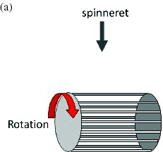
One of the most common modifications of the electrospinning setup is the addition of a rotating drum or a moving stage. In particular, a rotating drum is often used to collect aligned nanofibers through mechanical winding of the nanofiber onto it. The performance of electrospun fiber assemblies is highly dependent on the fiber anisotropy and molecular structure. Using a rotating drum collector, the fiber can be mechanically drawn, which affects its molecular structure and mechanical properties [115, 120]. MECC successfully fabricated a nanofibrous membrane with better alignment that exhibited silk-like reflection as shown in figure 9. They also succeeded in scaling up the process of fabricating aligned-fiber membranes using a modified drum collector system as shown in figure 9.
Figure 9.
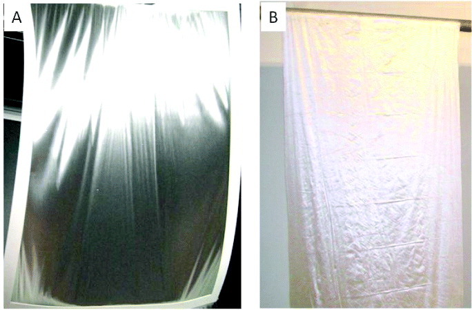
Aligned nanofibrous mesh. (A) A4 size membrane showing silk-like reflection when it is curved (B). The aligned mesh is 1 m wide and 3 m long.
Yarn
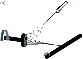
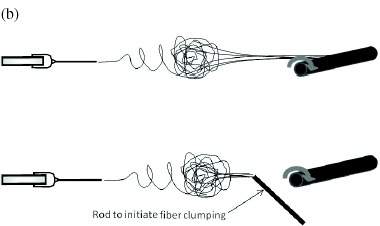
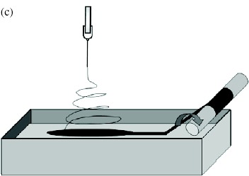
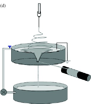
Electrospinning has been considered as a fiber and yarn fabrication method since as early as the 1930 s. However, probably owing to the higher production rate, other fabrication methods such as dry, wet and melt spinning have dominated the industry. Nevertheless, the interest in nanotechnology has led researchers to develop continuous electrospun nanofibrous yarns that are sufficiently strong to be handled. Khil et al and Smit et al reported a simple and elegant method of depositing nanofibers on water and drawing the deposited mesh on a rotating drum. As the nanofiber mesh was lifted off the water, the surface tension of the water acting on the fiber bundled the nanofibers into a yarn [73, 75]. Teo et al [74] reported an improved method of using a water flow in the form of a vortex to bundle nanofibers into a continuous yarn. The take-up speed using this method is more than 20 times faster than the method described by Smit et al. This is probably due to the partial formation of a yarn in the water vortex making the yarn sufficiently strong for fast collection. While the use of a liquid as a collecting substrate has been successful, the necessity of drying the deposited yarn is a disadvantage. Lee et al [77] showed that it is possible to deposit nanofibers on a solid substrate and draw the nanofibers into a yarn from it. Since a nanofiber mesh generally adheres reasonably well to a solid substrate, this process may increase the likelihood of fiber breakage during yarn formation. To reduce fiber adhesion to a solid substrate, Dabirian et al applied a sufficiently high negative voltage to the plate and needle. This reduced the velocity of the electrospinning jet as it span towards the plate and deflected it towards the take-up unit (see table 4(f)). The nanofiber bundle was then twisted as it was rolled onto the take-up mandrel [121].
Table 4.
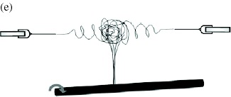
Nanofibrous yarn fabrication process
| Polymer: poly(amide-imide) | |
 |
Yarn take-up speed: unknown [77]. |
| Polymer: polylactide/single-wall carbon | |
| nanotube and polyacrylonitrile/single-wall | |
| carbon nanotube. | |
| Yarn take-up speed: unknown [79]. | |
| Polymer: acrylic terpolymer. | |
| Yarn take-up speed: unknown [78]. | |
| Polymer: polyacrylonitrile. | |
| Yarn take-up speed: 12 m min−1 (without any | |
| additives); 54 m min−1 (with addition of | |
| organic salt) [88]. | |
| Polymer: poly(vinyl pyrrolidine). | |
| Yarn take-up speed: unknown. | |
 |
Remark: ac power supply [12]. |
| Polymer: poly(vinylidene difluoride), | |
| poly(vinyl acetate) and polyacrylonitrile. | |
| Yarn take-up speed: 3 m min−1 [73]. | |
| Polymer: polycaprolactone. | |
 |
Yarn take-up speed: 30 m min−1 [75]. |
| Polymer: poly(vinylidene fluoride-co- | |
| hexafluoropropylene). | |
 |
Yarn take-up speed: 63 m min−1 [74]. |
| Polymer: polyvinylpyrrolidone. | |
| Yarn take-up speed: 894 m min−1 [122]. | |
| Polymer: polyvinyl alcohol | |
| Yarn take-up speed: 258 m min−1 [122]. | |
| Polymer: poly(L-lactic acid). | |
| Yarn take-up speed: 45 m min−1 [80]. | |
| Polymer: zein/ poly(L-lactic acid). | |
 |
Yarn take-up speed: 10 m min−1 [81]. |
| Polymer: polyacrylonitrile. | |
| Yarn take-up speed: 0.234 m min−1 | |
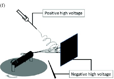 |
Remark: twisted yarn [121]. |
Given the appropriate selection of materials and/or spinning conditions, clumps of fibers can be formed in mid-air, which allows the fibers to be drawn into a yarn without further assistance [78, 79]. In some cases, a conductive rod may be introduced into the trajectory of the electrospinning jet to promote the coalescence of nanofibers [78]. The fiber clump may also form as a result of extremely chaotic jet movement causing sections of the jet to merge into a cross-linked network [29]. Wang et al [88] showed that the addition of salt to the solution facilitates the formation of nanofiber clumps due to increased conductivity. A disadvantage is that such chaotic jets may be uncharacteristic for many solutions, thus limiting the range of materials that can be spun into nanofibrous yarns using this method. There is an alternative, less solution-specific method of forming fiber clumps in mid-air. This method requires at least one pair of electrospinning jets of opposing charges, which are attracted to one another in mid-flight and form a fiber clump that can be drawn into a yarn [80, 81, 122]. Using this method, Pan et al reported an astonishing yarn take-up speed of 894 m min−1, which is more than 14 times higher than the speed reported by Teo et al. At such a high take-up speed, the yarn diameter was only a few microns [122]. Given the low strength of nanofibers, it is interesting to note that this small diameter yarn with only a few nanofibers in each bundle was able to withstand the drawing force. Later publications by other researchers reported more modest yarn take-up speeds of between 10 and 45 m min−1, albeit with a different polymer [80, 81].
In an interesting report on the formation of a yarn by self-bundling nanofibers, Maheshwari et al used an ac power supply for electrospinning [12]. This seems contradictory because it has been demonstrated that ac voltage promotes stable jet formation owing to the presence of opposing charges on the jet [9], whereas the formation of a self-bundled yarn under dc voltage requires the electrospinning jet to be chaotic [88]. Closer examination of the yarn self-bundling under ac voltage revealed a very different mechanism. A high-speed camera showed that the electrospinning jet was split into several secondary jets of a similar diameter [12]. Maheshwari et al hypothesized that during one ac cycle, the stretching of a single jet was limited which resulted in partial solidification. Jets subsequently split off from the side, thereby creating branches of nanofibers along the electrospinning jet. These jets contained both negative and positive segments which bundled together in mid-air [12], similar to the case where pairs of oppositely charged electrospinning jets were used to form fiber clumps in mid-air [80, 81, 122]. Table 4 presents a summary of the various continuous yarn fabrication methods using electrospinning.
The fibrils of a yarn are often twisted to increase the consistency of its mechanical strength. Most of the nanofibrous yarn fabrication techniques described here does not include twisting of the yarn except for the setup reported by Dabirian et al [121]. Typically, a peripheral setup is required to twist the yarn after it has been formed. In the setup of Dabirian et al, the yarn collection speed was only 0.234 m min−1, probably due to the collection of the nanofiber on a solid substrate before drawing it into a yarn. Using a fluid as a collector, it is also possible to incorporate the twisting of the yarn during the fabrication. This can be achieved by first depositing the fibers on a water reservoir with a vortex. Instead of allowing the nanofibers to flow down the vortex, the nanofiber mesh can be drawn off the water surface with the vortex twisting the resultant yarn from below as it is being collected. Since nanofibers do not adhere strongly to a liquid, they can be easily drawn off the water surface. Recently, a twisted yarn collection speed of up to 7 m min−1 has been recorded using the water flow technique [123].
Nanofibrous yarn can be fabricated using liquid or solid substrate or in the air. Each of these techniques has its advantages and disadvantages. The main advantage of using a liquid as a working substrate is that controlling the fluid flow is relatively easy and yarns can be modified accordingly. The high surface tension of water assists in the consolidation of the yarn into a tighter bundle. However, a solid substrate collector and the collection of the yarn in the air eliminate the need to dry the yarn after formation. More importantly, if a liquid is used as a collector, it must be a nonsolvent to the electrospun polymer. Collecting yarn in the air may potentially give the highest production rate per spinneret.
3D scaffolds
The widespread use of electrospun nanofibers since the late 1990 s is due to their biomedical applications, particularly in artificial grafting. There have been numerous studies on this application using a flat nanofibrous mesh, even though many tissues are three-dimensional. It may be possible to continue depositing nanofibers using a conventional electrospinning setup until a sufficiently thick membrane is obtained; however, this process is very slow and it has been shown that cellular infiltration into the full thickness of such a scaffold is either limited or impossible [124–126]. Clearly, a faster method is required for the fabrication of a block scaffold that allows cell infiltration. Early attempts to create block nanofibrous structures were limited to stacking layers of fibers [70–72, 127] or depositing the fibers on microfibers [128–130]. To facilitate the stacking of layers, Tzezana et al deposited a nanofiber mesh on water so that it could be easily lifted off and layers of mesh could then be stacked using a plate [127]. Since nanofibers are generally very weak and difficult to manipulate, coating a layer of nanofibers on a substrate allows easier handling. In this case, nanofibers can be deposited on a nonwoven microfiber mesh and subsequently stacked [129] or rolled into a 3D mesh [128]. Thorvaldsson et al designed a setup where nanofibers were deposited on a single strand of microfiber that was wound onto a collector. The nanofiber-coated microfiber could then be used to form a 3D fiber mesh [130]. Other researchers combined a rapid prototyping technique with electrospinning to form a 3D scaffold. This was achieved by alternating the creation of a porous network layer with the rapid prototyping technique and depositing nanofibers on the layer using electrospinning. These composite scaffolds have been tested in cell cultures and the presence of nanofibers significantly increased cell adhesion and proliferation [82, 85–87]. Instead of using the rapid prototyping technique to build up the composite structure, Sakai et al mixed a flat mesh of nanofibers into a hydrogel [131]. As the nanofiber mesh is weak, it was held in within the hydrogel matrix. Instead of fabricating the nanofiber mesh before mixing with a hydrogel, Ekaputra et al used the simultaneous electrospinning of nanofibers and electrospraying of hydrogels to mix the two components. In this way, they were able to build up a highly porous composite with nanofibers evenly distributed throughout [126]. Generally, these composites have the advantage of higher mechanical strength and structural integrity than 3D scaffolds made from nanofibers only. Nevertheless, in some applications, it may be useful to generate nanofiber-only scaffolds to maximize the surface area.
There are several methods of creating ordered or disordered 3D nanofibrous block structures. Isolated nanofibers are arranged randomly in the simplest 3D nanofibrous blocks. The main challenge in electrospinning to form 3D block structure is that the deposited fibers are compacted to form a flat mesh. To overcome this compaction, one has to create depth during the deposition. Nam et al sprinkled salt particles concurrently with electrospinning. The salt particles acted as scaffolding, enabling rapid build-up of the nanofibrous volume. The salt particles were washed away after a desired thickness was reached [132]. Alternatively, the use of a collector that is cooled to below the freezing point of water promotes ice crystal formation as the fiber is deposited onto it [124, 133]. Schneider et al [133] used dry ice to cool a collector and demonstrated that ice crystals form over the nanofibers as they are deposited, created depth in the nanofibrous structure. Instead of building up a scaffold, a liquid with low surface tension such as methanol can be used so that the fiber sinks as it touches the surface. This has been demonstrated by electrospinning over an organic solvent bath [83, 84]. The nanofibrous mesh does not become compacted as more nanofiber is deposited. However, as the nanofiber is very light, it tends to remain immediately below the surface of the liquid and it may take time before the layers grow to a sufficient thickness. Since nanofibers are quickly discharged as they sink below the solvent surface, the deposition area is expected to be smaller and the accumulation of nanofibers in the vertical direction is expected to be faster compared with conventional spinning on solid surfaces. Organic solvents are volatile and it is unclear whether their vapors will affect the electric field. The high flammability of most volatile organic solvents may render them unsuitable for the mass production of 3D nanofibrous scaffolds. Finally, although the described methods could be used to form 3D nanofibrous structures, the process is still relatively slow as it requires the layers to be built up and the pore size may still be relatively small.
A more effective method is to form an open and porous scaffold from the nanofibers during electrospinning. A flat mesh forms when the accelerated and charged nanofibers press on top of one another on a grounded collector, therefore reducing the speed of the nanofiber reduces nanofiber compaction. Miyamoto et al used a negatively charged electrode to generate ions so that the electrospinning jet was diverted and neutralized as it was collected on a mesh [134] (see figure 10). The diversion of the electrospinning jet path ensured that the nanofibers traveled at a very low speed. Similarly, if the distance between the spinneret tip and the collector is large enough, the nanofiber may decelerate sufficiently and a charged air current may be used to gather the nanofibers into block structures. In these cases, since the nanofibers were not compacted during the deposition, fluffy 3D nanofibers could be quickly formed.
Figure 10.
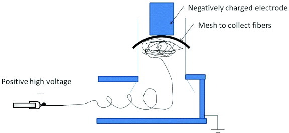
Setup used to form 3D nanofibrous scaffold using a negatively charged electrode or negative ion generator.
Progressing beyond the random organization of nanofibers, new techniques have been developed to create 3D nanofibrous block structures, each with a different microstructure. One simple method is to fabricate a thinner flat nanofibrous mesh that is sufficiently soft to be crushed into a 3D block. The nanofibrous mesh may be deposited on a liquid surface so that the mesh can be easily removed (see figure 11(a)). Alternatively, the fabricated flat nanofibrous mesh may be cut into small pieces before scraping it off the substrate to form a clump. The nanofibrous pieces may be mixed with fibrin glue or an adhesive to retain the 3D structure (see figure 11(b)). The microstructure of the 3D scaffolds mentioned so far was made of a nonwoven nanofibrous mesh. Other nanofibrous microstructures have been fabricated using water as a supporting substrate. Using an inclined water flow technique as shown in figure 12, a single layer of nanofibers can be collected on the water surface. The floating single nanofiber layer will collapse into a 3D scaffold when lifted off the water surface. Alternatively, such layers may be accumulated to form a 3D scaffold using another water inlet to impact the fibers floating on the surface. Unlike the previously described scaffolds, this scaffold is composed of aligned nanofiber fragments (see figure 11(d)). Instead of applying an inclined water flow, a water vortex similar to that used to fabricate a nanofiber yarn has been used to fabricate 3D nanofibrous scaffolds by allowing the nanofibrous yarn to collect in the basin below the vortex. A scaffold made from clumps of 3D nanofibers consisting of nanofibrous yarn can be gradually constructed using this technique [76] (see figure 11(c)).
Figure 11.
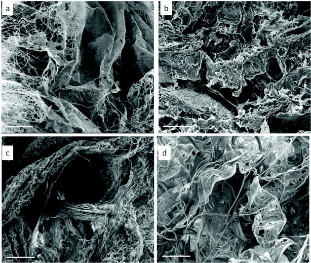
3D nanofibrous scaffolds with different microstructures. (a) Random nanofibrous mesh made of a single membrane, (b) random nanofibrous mesh made of a chopped membrane, (c) nanofibrous yarn, (d) lamellar single-layer nanofiber.
Figure 12.
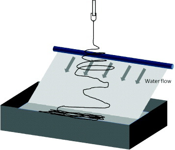
Inclined water flow method used to fabricate 3D nanofibrous structure with single-nanofiber-layer wall microstructure.
A hierarchical 3D arrangement of nanofibers may affect the interaction between cells, as natural extracellular matrices are organized differently for various tissues and organs. Organized structures may also be useful in other applications as their surface area and the fluid flow through them will depend on the nanofiber arrangement. However, one drawback of nanofiber blocks made by electrospinning is that they are soft and fluffy, with a cotton-like structure when dry, and break into smaller parts upon contact with a liquid.
Precision electrospinning
The ability to precisely control fiber deposition to form patterns using electrospinning can significantly expand the application of this technique and improve device performance. For example, signals from sensors made of nanofibers can be quickly routed to a receiver. Although conductive nanofibers have been fabricated using electrospinning, the chaotic nature of the deposition process seems incompatible with the high accuracy required for the fabrication of electronic devices. Nevertheless, electrospinning does offer several advantages over existing methods. Firstly, it is a relatively fast process and can be used for the rapid prototyping of nanofibrous devices. Secondly, it is very simple to obtain fibers with diameter smaller than 500 nm with this technique. Thirdly, the nanofiber is continuous which reduces the likelihood of a breakage in the connection compared with ink-jet printing methods.
For the precise and accurate deposition of nanofibers, the movement of the nanofiber relative to the collector must be sufficiently fast to prevent the nanofiber from buckling as it hits the collector [135]. However, moving parts generate air turbulence, which will disrupt the precision and accuracy of fiber deposition. As discussed above, the electrospinning jet can be controlled using secondary electrodes to alter the electric field profile. The generation of turbulence can also be avoided and jet deflection can be controlled electronically without any moving parts. Control of the electrospinning jet steering in the millimeter range has been demonstrated [36]. However, the fiber deposition area is likely to be limited by the electric field.
To progress beyond a simple nanofiber alignment, it is necessary to deposit the fibers before the bending instability occurs. Given that the length of the stable jet is only a few millimeters to a few centimeters in most setups, some researchers have resorted to moving the collector to within this distance. Early adopters of this spinning technique, named near-field electrospinning, used an atomic force microscope tip or a similar probe as the spinneret and their aim was to deposit fibers over trenches or other structures [111, 112, 136]. Later, Sun et al [137] created patterns of nanofibers using this method. However, as the spinneret can only contain a very small volume of solution, it is not possible to create larger nanofiber patterns. Gupta et al used a needle connected to a solution reservoir in the near-field setup and made a further improvement by installing a needle-tip guiding-electrode below the collector. They were able to create a grid from electrospun fibers with a precision of about 250 μm, but the fibers were 15–50 μm in diameter [59]. Hellmann et al used a smaller capillary tip of 50 μm diameter for near-field electrospinning. The collector was given a negative charge, probably to generate a greater attractive force on the spinning jet. At a tip to collector distance of 0.5 mm, the position of the nanofibers could be controlled down to a few μm with a linear collector speed of 1 mm s−1. When the tip to collector distance was increased, the precision was reduced correspondingly [138]. Given the importance of having a stable jet for precision electrospinning, He et al proposed the following equation to predict the length of the stable jet [139]:
where R0=( 2σ Q/πkρE)1/3 Q is the flow rate, σ is the surface charge, k is the dimensionless conductivity, E is the applied electric field, I is the current passing through the jet, ρ is the liquid density and r0 is the initial radius of the jet.
Although this equation may be used to estimate the stable jet length in a typical nozzle-to-collector electrospinning setup, it is not applicable for setups with auxiliary electrodes. Nevertheless, it indicates the parameters that affect jet stability.
To increase the stability of the electrospinning jet, several processing parameters should be taken into account. As mentioned in an earlier section, one of the criteria affecting the bending instability is the surface charge. However, the electric field strength at the nozzle, the solution viscosity and the stiffness of the solution also play an important role in maintaining stability of the electrospinning jet. A high electric field at the nozzle causes the jet to stretch along its axis and the resulting tensile force inhibits the formation of capillary instability [140]. Several studies using the tip to collector setup have shown that raising the applied voltage increases the length of the stable jet [140, 141]. Using a base electrode, the electric field acting on the electrospinning jet will be more focused thereby creating a longer stable jet than that with a spinneret tip [26]. However, contrary to the case of using a tip to collector system, a higher voltage applied to the base electrode leads to a more significant increase in the surface charge density thus reducing the stable jet length [26, 28]. On the basis of the principle that a solution with higher stiffness more strongly inhibits the formation of the bending instability, Baumgarten showed that the stable jet length increases with increasing concentration of acrylic resin in dimethyl formamide [30]. Numerical modeling by Kowalewski et al [141] showed that a more stable jet is formed with increased viscosity and elastic modulus. However, increasing the viscosity and concentration of the solution also results in a larger fiber diameter. The use of a more viscous polymer melt also improves the spinning jet stability, which can be used to create various forms of patterns [142]. Choosing a solvent with a higher evaporation rate will result in a stiffer electrospinning jet, thereby enhancing the electrospinning jet stability. Using a polymer that is stiffer may also help reduce the bending instability, although this has yet to be investigated for precision electrospinning.
In the tip-to-collector setup, although increasing the voltage leads to a corresponding increase in the length of the stable jet, the increased acceleration of the jet may hinder the creation of patterned structures. The buckling of the nanofiber upon impact will be greater at a higher jet velocity. Since a high surface charge density is the cause of the bending instability, reducing it will lead to a more stable jet. Chang et al [143] showed that spinning below the critical voltage enables more precise electrospinning. Using a needle tip of 100 μm inner diameter as a spinneret, which was connected to a solution reservoir, they were able to generate patterned nanofibers (fiber diameter 150 nm) with a precision of 50 μm. However, since the spinning was carried out below the critical voltage, a tungsten tip was required to initiate the spinning by drawing the solution onto the collector. A patterned grid can be generated by moving the collector stage [143]. Although the charges cannot be eliminated as they are required to stretch the fibers, it is still possible to reduce the overall instability of the jet due to charge repulsion through the use of ac instead of the conventional dc high-voltage power supply [9–11]. An electrospinning jet with alternating charges is subjected to less bending instability resulting in more ordered structures [9]. The interaction between the regions of alternating charges can be optimized so that a stable jet is formed for each polymer solution [10]. Another advantage of using ac voltage is that the accumulation of charges can be minimized. However, the use of ac voltage results in thick fibers [11]. The application of a magnetic field has been suggested as a means of reducing the bending instability [63] through the creation of a force that acts against direction of jet bending, but this has not been confirmed experimentally.
The ability to carry out precision electrospinning is vital for electronic applications. Experiments have been carried out to evaluate the conductivity of nanofibers for use in field-effect transistors [144–146]. A single ZnO nanofiber was found to be an intrinsic n-type semiconductor [144], and a regioregular poly(3-hexylthiophene) nanofiber [145] acts as a p-channel organic transistor. Improving the spatial precision is essential for realizing the potential of electrospinning for the fabrication of multiple transistors.
Future of electrospinning
Electrospinning has become an important technology enabling the scientific community to learn more about the properties of materials in the nanofiber form. Future advances in electrospinning are likely to be driven by applications, which require specialized nanofiber chemistry and structure, multifunctional hierarchical organizations and their scaling to industrial production. Techniques such as ultraviolet cutting [147], chemical fragmentation [148] and ion etching [149] have been developed to address the preference for short fibers in noninvasive surgical and solar energy applications [150]. Owing to the high surface area of nanofibers, interesting properties and improved device performance can be expected. From the commercial perspective, the application of electrospun nanofibers will be in high-performance or high-value-added products. In terms of the realization of ordered or more complex nanofibrous organizations and structures, electrospinning is superior to other nanofiber fabrication processes.
Conclusions
Over the last decade, advances in electrospinning have led to the structure of nanofibrous arrangements evolving from a nonwoven form to yarn, 3D assemblies and patterned structures. This review covers several techniques for electrospinning more advanced structures and how the principles behind these techniques can potentially be combined to achieve better control of the process. Owing to its relatively low cost, the low quantity of raw materials required, easy maintenance and the ease of fabricating nanofibers, electrospinning will remain a popular nanotechnology in laboratories and is expected to be adopted more widely in industry.
References
- Ramakrishna S, Fujihara K, Teo W E, Yong T, Ma Z. and Ramaseshan R. Mater. Today. 2006;9:40. doi: 10.1016/S1369-7021(06)71389-X. [DOI] [Google Scholar]
- Teo W E, He W. and Ramakrishna S. Biotechnol. J. 2006;1:918. doi: 10.1002/(ISSN)1860-7314. [DOI] [PubMed] [Google Scholar]
- Teo W E. and Ramakrishna S. Compos. Sci. Technol. 2009;69:1804. doi: 10.1016/j.compscitech.2009.04.015. [DOI] [Google Scholar]
- Teo W E. and Ramakrishna S. Nanotechnology. 2006;17:R89. doi: 10.1088/0957-4484/17/14/R01. [DOI] [PubMed] [Google Scholar]
- Rutledge G C, Shin M Y, Warner S B, Buer A, Grimler M. and Ugbolue S C. National Textile Center Annual Report M98–D01 2000 [Google Scholar]
- Reznik S N, Yarin A L, Theron A. and Zussman E. J. Fluid Mech. 2004;516:349. doi: 10.1017/S0022112004000679. [DOI] [Google Scholar]
- Deitzel J M, Kleinmeyer J, Harris D. and Tan N C B. Polymer. 2001;42:261. doi: 10.1016/S0032-3861(00)00250-0. [DOI] [Google Scholar]
- Samatham R. and Kim K J. Polym. Eng. Sci. 2006;46:954. doi: 10.1002/(ISSN)1548-2634. [DOI] [Google Scholar]
- Kessick R, Fenn J. and Tepper G. Polymer. 2004;45:2981. doi: 10.1016/j.polymer.2004.02.056. [DOI] [Google Scholar]
- Sarkar S, Deevi S. and Tepper G. Macromol. Rapid Commun. 2007;28:1034. doi: 10.1002/(ISSN)1521-3927. [DOI] [Google Scholar]
- Yeo L Y, Gagnon Z. and Chang H C. Biomaterials. 2005;26:6122. doi: 10.1016/j.biomaterials.2005.03.033. [DOI] [PubMed] [Google Scholar]
- Maheshwari S. and Chang H C. Adv. Mater. 2009;21:349. doi: 10.1002/adma.v21:3. [DOI] [Google Scholar]
- Kalayci V, Patra P K, Kim Y K, Ugbolue S C. and Warner S B. Polymer. 2005;46:7191. doi: 10.1016/j.polymer.2005.06.041. [DOI] [Google Scholar]
- Yarin A L, Koombhongse S. and Reneker D H. J. Appl. Phys. 2001;90:4836. doi: 10.1063/1.1408260. [DOI] [Google Scholar]
- Varabhas J S, Chase G G. and Reneker D. Polymer. 2008;49:4226. doi: 10.1016/j.polymer.2008.07.043. [DOI] [Google Scholar]
- O'Konski C T, Thacher H C., Jr J. Phys. Chem. 1953;57:955. doi: 10.1021/j150510a024. [DOI] [Google Scholar]
- Macky W A. Proc. R. Soc. 1931;133(A):565. doi: 10.1098/rspa.1931.0168. [DOI] [Google Scholar]
- Miloh T, Spivak B. and Yarin A L. J. Appl. Phys. 2009;106:114910. doi: 10.1063/1.3264884. [DOI] [Google Scholar]
- Taylor G. Proc. R. Soc. 1964;280(A):383. doi: 10.1098/rspa.1964.0151. [DOI] [Google Scholar]
- Kostakova E, Meszaros L. and Gregr J. Mater. Lett. 2009;63:2419. doi: 10.1016/j.matlet.2009.08.014. [DOI] [Google Scholar]
- Niu H, Lin T. and Wang X. J. Appl. Polym. Sci. 2009;114:3524. doi: 10.1002/app.v114:6. [DOI] [Google Scholar]
- Yarin A L. and Zussman E. Polymer. 2004;45:2977. doi: 10.1016/j.polymer.2004.02.066. [DOI] [Google Scholar]
- Lukas D, Sarkar A. and Pokomy P. J. Appl. Phys. 2008;103:084309. doi: 10.1063/1.2907967. [DOI] [Google Scholar]
- He J H, Liu Y, Xu L, Yu J Y. and Sun G. Chaos Solitons Fractals. 2008;37:643. doi: 10.1016/j.chaos.2007.11.028. [DOI] [Google Scholar]
- Shin Y M, Hohman M M, Brenner M P. and Rutledge G C. Polymer. 2001;42:9955. doi: 10.1016/S0032-3861(01)00540-7. [DOI] [Google Scholar]
- Yang Y, Jia Z, Liu J, Li Q, Hou L, Wang L. and Guan Z. J. Appl. Phys. 2008;103:104307. doi: 10.1063/1.2924439. [DOI] [Google Scholar]
- Taylor G. Proc. R. Soc. 1969;313(A):453. doi: 10.1098/rspa.1969.0205. [DOI] [Google Scholar]
- Homan M M, Shin M, Rutledge G. and Brenner M P. Phys. Fluids. 2001;13:2201. doi: 10.1063/1.1383791. [DOI] [Google Scholar]
- Reneker D H, Kataphinan W, Theron A, Zussman E. and Yarin A L. Polymer. 2002;43:6785. doi: 10.1016/S0032-3861(02)00595-5. [DOI] [Google Scholar]
- Baumgarten P K. J. Colloid Interface Sci. 1971;36:71. doi: 10.1016/0021-9797(71)90241-4. [DOI] [Google Scholar]
- Theron S, Zussman E. and Yarin A. Polymer. 2004;45:2017. doi: 10.1016/j.polymer.2004.01.024. [DOI] [Google Scholar]
- Fong H, Chung I. and Reneker D H. Polymer. 1999;40:4585. doi: 10.1016/S0032-3861(99)00068-3. [DOI] [Google Scholar]
- Deitzel J M, Kleinmeyer J D, Hirvonen J K. and Tan N C B. Polymer. 2001;42:8163. doi: 10.1016/S0032-3861(01)00336-6. [DOI] [Google Scholar]
- Liu L. and Dzenis Y A. Nanotechnology. 2008;19:355307. doi: 10.1088/0957-4484/19/35/355307. [DOI] [PubMed] [Google Scholar]
- Li D, Wang Y. and Xia Y. Nano Lett. 2003;3:1167. doi: 10.1021/nl0344256. [DOI] [Google Scholar]
- Bellan L M. and Craighead H G. J. Vac. Sci. Technol. 2006;24(B):3179. doi: 10.1116/1.2363403. [DOI] [Google Scholar]
- Hohman M M, Shin M, Rutledge G. and Brenner M P. Phys. Fluids. 2001;13:2221. doi: 10.1063/1.1384013. [DOI] [Google Scholar]
- Kim G H. Biomed. Mater. 2008;3:025010. doi: 10.1088/1748-6041/3/2/025010. [DOI] [PubMed] [Google Scholar]
- Kim G H. and Kim W D. Appl. Phys. Lett. 2006;89:013111. doi: 10.1063/1.2217924. [DOI] [Google Scholar]
- Buttafoco L, Kolkman N G, Engbers-Buijtenhuijs P, Poot A A, Dijkstra P J, Vermes I. and Feijen J. Biomaterials. 2006;27:724. doi: 10.1016/j.biomaterials.2005.06.024. [DOI] [PubMed] [Google Scholar]
- Salim A, Son C. and Ziaie B. Nanotechnology. 2008;19:375303. doi: 10.1088/0957-4484/19/37/375303. [DOI] [PubMed] [Google Scholar]
- Acharya M, Arumugam G K. and Heiden P A. Macromol. Mater. Eng. 2008;293:666. doi: 10.1002/mame.v293:8. [DOI] [Google Scholar]
- Theron A, Zussman E. and Yarin A L. Nanotechnology. 2001;12:384. doi: 10.1088/0957-4484/12/3/329. [DOI] [Google Scholar]
- Munir M M, Widiyandari H, Iskandar F. and Okuyama K. Nanotechnology. 2008;19:375601. doi: 10.1088/0957-4484/19/37/375601. [DOI] [PubMed] [Google Scholar]
- Gibson P. and Schreuder-Gibson H. Int. Nonwovens J. 2004;13:34. [Google Scholar]
- Wang Y, Wang G, Chen L, Li H, Yin T, Wang B, Lee J C M. and Yu Q. Biofabrication. 2009;1:015001. doi: 10.1088/1758-5082/1/1/015001. [DOI] [PubMed] [Google Scholar]
- Zhang D. and Chang J. Nano Lett. 2008;8:3283. doi: 10.1021/nl801667s. [DOI] [PubMed] [Google Scholar]
- Zhang K, Wang X, Jing D, Yang Y. and Zhu M. Biomed. Mater. 2009;4:35004. doi: 10.1088/1748-6041/4/3/035004. [DOI] [PubMed] [Google Scholar]
- Beachley V. and Wen X. Mater. Sci. Eng. 2009;29(C):663. doi: 10.1016/j.msec.2008.10.037. [DOI] [PMC free article] [PubMed] [Google Scholar]
- Ishii Y, Sakai H. and Murata H. Mater. Lett. 2008;62:3370. doi: 10.1016/j.matlet.2008.03.038. [DOI] [Google Scholar]
- Li D, Wang Y. and Xia Y. Adv. Mater. 2004;16:361. doi: 10.1002/(ISSN)1521-4095. [DOI] [Google Scholar]
- Teo W E. and Ramakrishna S. Nanotechnology. 2005;16:1878. doi: 10.1088/0957-4484/16/9/077. [DOI] [Google Scholar]
- Dalton P D, Klee D. and Moller M. Polym. Commun. 2005;46:611. [Google Scholar]
- Lotus A F, Bender E T, Evans E A, Ramiser R D, Reneker D H. and Chase G G. J. Appl. Phys. 2008;103:024910. doi: 10.1063/1.2831362. [DOI] [Google Scholar]
- Katta P, Alessandro M, Ramsier R D. and Chase G G. Nano Lett. 2004;4:2215. doi: 10.1021/nl0486158. [DOI] [Google Scholar]
- Afifi A M, Nakajima H, Yamane H, Kimura Y. and Nakano S. Macromol. Mater. Eng. 2009;294:658. doi: 10.1002/mame.v294:10. [DOI] [Google Scholar]
- Rafique J, Yu J, Fang G, Wong K W, Zheng Z, Ong H. and Lau W M. Appl. Phys. Lett. 2007;91:063126. doi: 10.1063/1.2768871. [DOI] [Google Scholar]
- Teo W E, Kotaki M, Mo X M. and Ramakrishna S. Nanotechnology. 2005;16:918. doi: 10.1088/0957-4484/16/6/049. [DOI] [PubMed] [Google Scholar]
- Gupta A, Seifalian M, Ahmad Z, Edirisinghe M J. and Winslet M C. J. Bioact. Compat. Polym. 2007;22:265. doi: 10.1177/0883911507078268. [DOI] [Google Scholar]
- Sundaray B, Subramanian V, Natarajan T S, Xiang R Z, Chang C C. and Fann W S. Appl. Phys. Lett. 2004;84:1222. doi: 10.1063/1.1647685. [DOI] [Google Scholar]
- Carnell L S, Siochi E J, Holloway N M, Stephens R M, Rhim C, Niklason L E. and Clark R I. Macromolecules. 2008;41:5345. doi: 10.1021/ma8000143. [DOI] [Google Scholar]
- Wu Y, Carnell L A. and Clark R L. Polymer. 2007;48:5653. doi: 10.1016/j.polymer.2007.07.023. [DOI] [Google Scholar]
- Wu Y, Yu J Y, He J H. and Wan Y Q. Chaos, Solitons Fractals. 2007;32:5. doi: 10.1016/j.chaos.2006.05.023. [DOI] [PMC free article] [PubMed] [Google Scholar]
- Ajao J A, Abioma A A, Chigome S, Fasasi A Y, Osinkolu G A. and Maaza M. J. Mater. Sci. 2011:at press. [Google Scholar]
- Larsen G, Spretz R. and Velarde-Ortiz R. Adv. Mater. 2004;16:166. doi: 10.1002/(ISSN)1521-4095. [DOI] [Google Scholar]
- Um I C, Fang D, Hsiao B S, Okamoto A. and Chu B. Biomacromolecules. 2004;5:1428. doi: 10.1021/bm034539b. [DOI] [PubMed] [Google Scholar]
- Rein D M, Cohen Y, Ronen A, Shuster K. and Zussman E. Polym. Eng. Sci. 2009;49:774. doi: 10.1002/pen.v49:4. [DOI] [Google Scholar]
- Varesano A, Montarsolo A. and Tonin C. Eur. Polym. J. 2007;43:2792. doi: 10.1016/j.eurpolymj.2007.04.023. [DOI] [Google Scholar]
- Madduri S, Papaloïzos M. and Gander B. Biomaterials. 2010;31:2323. doi: 10.1016/j.biomaterials.2009.11.073. [DOI] [PubMed] [Google Scholar]
- Inanç B, Arslan Y E, Seker S, Elçin A E. and Elçin Y M. J. Biomed. Mater. Res. 2009;90(A):186. doi: 10.1002/jbm.a.32066. [DOI] [PubMed] [Google Scholar]
- Srouji S, Kizhner T, Suss-Tobi E, Livne E. and Zussman E. J. Mater. Sci. Mater. Med. 2008;19:1249. doi: 10.1007/s10856-007-3218-z. [DOI] [PubMed] [Google Scholar]
- Yang X, Shah J D. and Wang H. Tissue Eng. 2009;15(A):945. doi: 10.1089/ten.tea.2007.0280. [DOI] [PubMed] [Google Scholar]
- Smit E, Buttner U. and Sanderson R D. Polymer. 2005;46:2419. doi: 10.1016/j.polymer.2005.02.002. [DOI] [Google Scholar]
- Teo W, Gopal R, Ramaseshan R, Fujihara K. and Ramakrishna S. Polymer. 2007;48:3400. doi: 10.1016/j.polymer.2007.04.044. [DOI] [Google Scholar]
- Khil M S, Bhattarai S R, Kim H Y, Kim S Z. and Lee K H. J. Biomed. Mater. Res. 2005;72(B):117. doi: 10.1002/(ISSN)1097-4636. [DOI] [PubMed] [Google Scholar]
- Teo W, Liao S, Chan C. and Ramakrishna S. Curr. Nanosci. 2008;4:361. doi: 10.2174/157341308786306080. [DOI] [Google Scholar]
- Lee S H, Kim S Y, Youn J R, Seng D G, Jee S Y, Choi J I. and Lee J R. Polym. Int. 2010;59:212. doi: 10.1002/pi.v59:12. [DOI] [Google Scholar]
- Mondal A, Borah R, Mukherjee A, Basu S, Jassal M. and Agrawal A K. J. Appl. Polym. Sci. 2008;110:603. doi: 10.1002/app.v110:1. [DOI] [Google Scholar]
- Ko F, Gogotsi Y, Ali A, Naguib N, Ye H, Yang G, Li C. and Willis P. Adv. Mater. 2003;15:1161. doi: 10.1002/adma.200304955. [DOI] [Google Scholar]
- Li X, Yao C, Sun F, Song T, Li Y. and Pu Y. J. Appl. Polym. Sci. 2008;107:3756. doi: 10.1002/(ISSN)1097-4628. [DOI] [Google Scholar]
- Yao C, Li X. and Song T. J. Appl. Polym. Sci. 2009;114:2079. doi: 10.1002/app.v114:4. [DOI] [Google Scholar]
- Park S H, Kim T G, Kim H C, Yang D Y. and Park T G. Acta Biomater. 2008;4:1198. doi: 10.1016/j.actbio.2008.03.019. [DOI] [PubMed] [Google Scholar]
- Yokoyama Y, Hattori S, Yoshikawa C, Yasuda Y, Koyama H, Takato T. and Kobayashi H. Mater. Lett. 2009;63:754. doi: 10.1016/j.matlet.2008.12.042. [DOI] [Google Scholar]
- Ki C S, Kim J W, Hyun J H, Lee K H, Hattori M, Rah D K. and Park Y H. J. Appl. Polym. Sci. 2007;106:3922. doi: 10.1002/app.v106:6. [DOI] [Google Scholar]
- Moroni L, Schotel R, Hamann D, de Wijn J R. and van Blitterswijk C A. Adv. Funct. Mater. 2008;18:53. doi: 10.1002/(ISSN)1616-3028. [DOI] [Google Scholar]
- Kim G H, Son J G, Park S A. and Kim W D. Macromol. Rapid Commun. 2008;29:1577. doi: 10.1002/marc.v29:19. [DOI] [Google Scholar]
- Martins A, Chung S, Pedro A J, Sousa R A, Marques A P, Reis R L. and Neves N M. J. Tissue Eng. Regen. Med. 2009;3:37. doi: 10.1002/term.v3:1. [DOI] [PubMed] [Google Scholar]
- Wang X, Zhang K, Zhu M, Yu H, Zhou Z, Chen Y. and Hsiao B S. Polymer. 2008;49:2755. doi: 10.1016/j.polymer.2008.04.015. [DOI] [Google Scholar]
- Okuzaki H, Takahashi T, Hara Y. and Yan H. J. Polym. Sci. 2008;46(B):305. doi: 10.1002/(ISSN)1099-0488. [DOI] [Google Scholar]
- Tian S, Ogata N, Shimada N, Nakane K, Ogihara T. and Yu M. J. Appl. Polym. Sci. 2009;113:1282. doi: 10.1002/app.v113:2. [DOI] [Google Scholar]
- Deng R, Liu Y, Ding Y, Xie P, Luo L. and Yang W. J. Appl. Polym. Sci. 2009;114:166. doi: 10.1002/app.v114:1. [DOI] [Google Scholar]
- Wang C, Chien H S, Yan K W, Hung C L, Hung K L, Tsai S J. and Jhang H J. Polymer. 2009;50:6100. doi: 10.1016/j.polymer.2009.10.025. [DOI] [Google Scholar]
- He J H, Wan Y Q. and Yu J Y. Int. J. Nonlinear Sci. Numer. Simul. 2004;5:253. [Google Scholar]
- Hsu C M. and Shivkumar S. J. Mater. Sci. 2004;39:3003. doi: 10.1023/B:JMSC.0000025826.36080.cf. [DOI] [Google Scholar]
- Heikkila P. and Harlin A. Eur. Polym. J. 2008;44:3067. doi: 10.1016/j.eurpolymj.2008.06.032. [DOI] [Google Scholar]
- Haghi A K. and Akbari M. Phys. Status Solidi. 2007;204(A):1830. [Google Scholar]
- Lee K H, Kim H Y, Bang H J, Jung Y H. and Lee S G. Polymer. 2003;44:4029. doi: 10.1016/S0032-3861(03)00345-8. [DOI] [Google Scholar]
- Demir M M, Yilgor I, Yilgor E. and Erman B. Polymer. 2002;43:3303. doi: 10.1016/S0032-3861(02)00136-2. [DOI] [Google Scholar]
- Theron S A, Yarin A L, Zussman E. and Kroll E. Polymer. 2005;46:2889. doi: 10.1016/j.polymer.2005.01.054. [DOI] [Google Scholar]
- Varesano A, Carletto R A. and Mazzuchetti G. J. Mater. Process. Technol. 2009;209:5178. doi: 10.1016/j.jmatprotec.2009.03.003. [DOI] [Google Scholar]
- Reneker D H. and Yarin A L. Polymer. 2008;49:2387. doi: 10.1016/j.polymer.2008.02.002. [DOI] [Google Scholar]
- Kong C S, Yoo W S, Jo N G. and Kim H S. J. Macromol. Sci. 2010;49(B):122. doi: 10.1080/00222340903344390. [DOI] [Google Scholar]
- Eda G, Liu J. and Shivkumar S. Mater. Lett. 2007;61:1451. doi: 10.1016/j.matlet.2006.07.052. [DOI] [Google Scholar]
- Kong C S, Lee S G, Lee S H, Lee K H, Jo N G. and Kim H S. Polym. Eng. Sci. 2009;49:2286. doi: 10.1002/pen.v49:11. [DOI] [Google Scholar]
- Vaseashta A. Appl. Phys. Lett. 2007;90:093115. doi: 10.1063/1.2709958. [DOI] [Google Scholar]
- Wang X, Niu H. and Lin T. Polym. Eng. Sci. 2009;49:1582. doi: 10.1002/pen.v49:8. [DOI] [Google Scholar]
- Yang R, He J, Xu L. and Yu J. Polymer. 2009;50:5846. doi: 10.1016/j.polymer.2009.10.021. [DOI] [Google Scholar]
- Filatov Y, Budyk A. and Kirichenko V. Connecticut, NH Begell House; 2007. Electrospinning of Micro- and Nanofibers: Fundamentals and Applications in Separation and Filtration Process. [Google Scholar]
- Shein T I, Frenkel G G, Budnitskii G A. and Kudryavtsev G I. Fibre Chem. 1976;8:15. doi: 10.1007/BF00546589. [DOI] [Google Scholar]
- Postema A R, Luiten A H, Oostra H. and Pennings A J. J. Appl. Polym. Sci. 1990;39:1275. doi: 10.1002/app.1990.070390606. [DOI] [Google Scholar]
- Kameoka J. and Craighead H G. Appl. Phys. Lett. 2003;83:371. doi: 10.1063/1.1592638. [DOI] [Google Scholar]
- Kameoka J, Orth R, Yang Y, Czaplewski D, Mathers R, Coates G W. and Craighead H G. Nanotechnology. 2003;14:1124. doi: 10.1088/0957-4484/14/10/310. [DOI] [Google Scholar]
- Bellan L M. and Craighead H G. J. Appl. Phys. 2007;102:094308. doi: 10.1063/1.2799059. [DOI] [Google Scholar]
- Buer A, Ugbolue S C. and Warner S B. Text. Res. J. 2001;71:323. [Google Scholar]
- Fennessey S F. and Farris R J. Polymer. 2004;45:4217. doi: 10.1016/j.polymer.2004.04.001. [DOI] [Google Scholar]
- Behler K, Havel M. and Gogotsi Y. Polymer. 2007;48:6617. doi: 10.1016/j.polymer.2007.08.058. [DOI] [Google Scholar]
- Wang X, Cao J, Hu Z, Pan W. and Liu Z. J. Mater. Sci. Technol. 2006;22:536. [Google Scholar]
- Yarin A L, Kataphinan W. and Reneker D H. J. Appl. Phys. 2005;98:064501. doi: 10.1063/1.2060928. [DOI] [Google Scholar]
- Eda G, Liu J. and Shivkumar S. Eur. Polym. J. 2007;43:1154. doi: 10.1016/j.eurpolymj.2007.01.003. [DOI] [Google Scholar]
- Thomas V, Jose M V, Chowdhury S, Sullivan J F, Dean D R. and Vohra Y K. J. Biomater. Sci. Polym. Ed. 2006;17:969. doi: 10.1163/156856206778366022. [DOI] [PubMed] [Google Scholar]
- Dabirian F, Hosseini Y. and Ravandi S A H. J. Text. Inst. 2007;98:237. [Google Scholar]
- Pan H, Li L, Hu L. and Cui X. Polymer. 2006;47:4901. doi: 10.1016/j.polymer.2006.05.012. [DOI] [Google Scholar]
- Yousefzadeh M, Latifi M, Teo W E, Amani-Tehran M. and Ramakrishna S. Polym. Eng. Sci. 2011;51:323. doi: 10.1002/pen.v51.2. [DOI] [Google Scholar]
- Leong M F, Rasheed M Z, Lim T C. and Chian K S. J. Biomed. Mater. Res. 2009;91(A):231. doi: 10.1002/jbm.a.32208. [DOI] [PubMed] [Google Scholar]
- Baker B M. and Mauck R L. Biomaterials. 2007;28:1967. doi: 10.1016/j.biomaterials.2007.01.004. [DOI] [PMC free article] [PubMed] [Google Scholar]
- Ekaputra A K, Prestwich G D, Cool S M. and Hutmacher D W. Biomacromolecules. 2008;9:2097. doi: 10.1021/bm800565u. [DOI] [PubMed] [Google Scholar]
- Tzezana R, Zussman E. and Levenberg S. Tissue Eng. 2008;14(C):281. doi: 10.1089/ten.tec.2008.0201. [DOI] [PubMed] [Google Scholar]
- Shim I K, Suh W H, Lee S Y, Lee S H, Heo S J, Lee M C. and Lee S J. J. Biomed. Mater. Res. 2009;90(A):595. doi: 10.1002/jbm.a.32109. [DOI] [PubMed] [Google Scholar]
- Pham Q P, Sharma U. and Mikos A G. Biomacromolecules. 2006;7:2796. doi: 10.1021/bm060680j. [DOI] [PubMed] [Google Scholar]
- Thorvaldsson A, Stenhamre H, Gatenholm P. and Walkenström P. Biomacromolecules. 2008;9:1044. doi: 10.1021/bm701225a. [DOI] [PubMed] [Google Scholar]
- Sakai S, Takagi Y, Yamada Y, Yamaguchi T. and Kawakami K. Biomed. Mater. 2008;3:034102. doi: 10.1088/1748-6041/3/3/034102. [DOI] [PubMed] [Google Scholar]
- Nam J, Huang Y, Agarwal S. and Lannutti J. Tissue Eng. 2007;13:2249. doi: 10.1089/ten.2007.13.issue-9. [DOI] [PMC free article] [PubMed] [Google Scholar]
- Schneider O D, Weber F, Brunner T J, Loher S, Ehrbar M, Schmidlin P R. and Stark W J. Acta Biomater. 2009;5:1775. doi: 10.1016/j.actbio.2008.11.030. [DOI] [PubMed] [Google Scholar]
- Miyamoto K.et al Int. J. Biol. Macromol. 2009;45:33. doi: 10.1016/j.ijbiomac.2009.03.014. [DOI] [PubMed] [Google Scholar]
- Han T, Reneker D H. and Yarin A L. Polymer. 2007;48:6064. doi: 10.1016/j.polymer.2007.08.002. [DOI] [Google Scholar]
- Wu Y, Johannes M S. and Clark R L. Mater. Lett. 2008;62:699. doi: 10.1016/j.matlet.2007.06.052. [DOI] [Google Scholar]
- Sun D, Chang C, Li S. and Lin L. Nano Lett. 2006;6:839. doi: 10.1021/nl0602701. [DOI] [PubMed] [Google Scholar]
- Hellmann C, Belardi K, Dersch R, Greiner A, Wendorff J H. and Bahnmueller S. Polymer. 2009;23:1197. doi: 10.1016/j.polymer.2009.01.029. [DOI] [Google Scholar]
- He J H, Wu Y. and Zuo W W. Polymer. 2005;46:12637. doi: 10.1016/j.polymer.2005.10.130. [DOI] [Google Scholar]
- Reneker D, Yarin A, Fong H. and Koombhongse S. J. Appl. Phys. 2000;87:4531. doi: 10.1063/1.373532. [DOI] [Google Scholar]
- Kowalewski T A, Blonski S. and Barral S. Bull. Polym. Acad. Sci.: Tech. Sci. 2005;53:385. [Google Scholar]
- Dalton P D, Joergensen N T, Groll J. and Moeller M. Biomed. Mater. 2008;3:034109. doi: 10.1088/1748-6041/3/3/034109. [DOI] [PubMed] [Google Scholar]
- Chang C, Limkrailassiri K. and Lin L. Appl. Phys. Lett. 2008;93:123111. doi: 10.1063/1.2975834. [DOI] [Google Scholar]
- Wu H, Lin D, Zhang R. and Pan W. J. Am. Ceram. Soc. 2008;91:656. doi: 10.1111/jace.2008.91.issue-2. [DOI] [Google Scholar]
- Liu H, Reccius C H. and Craighead H G. Appl. Phys. Lett. 2005;87:253106. doi: 10.1063/1.2149980. [DOI] [Google Scholar]
- Gonzalez R. and Pinto N J. Synth. Met. 2005;151:275. doi: 10.1016/j.synthmet.2005.05.007. [DOI] [Google Scholar]
- Stoiljkovic A. and Agarwal S. Macromol. Mater. Eng. 2008;293:895. doi: 10.1002/mame.v293:11. [DOI] [Google Scholar]
- Kim T G. and Park T G. Macromol. Rapid Commun. 2008;29:1231. doi: 10.1002/marc.v29:14. [DOI] [Google Scholar]
- Shi J, Wang L. and Chen Y. Langmuir. 2009;25:6015. doi: 10.1021/la900811k. [DOI] [PubMed] [Google Scholar]
- Fujihara K, Kumar A, Jose R, Ramakrishna S. and Uchida S. Nanotechnology. 2007;18:365709. doi: 10.1088/0957-4484/18/36/365709. [DOI] [Google Scholar]


