Abstract
The electric current activated/assisted sintering (ECAS) is an ever growing class of versatile techniques for sintering particulate materials. Despite the tremendous advances over the last two decades in ECASed materials and products there is a lack of comprehensive reviews on ECAS apparatuses and methods. This paper fills the gap by tracing the progress of ECAS technology from 1906 to 2008 and surveys 642 ECAS patents published over more than a century. It is found that the ECAS technology was pioneered by Bloxam (1906 GB Patent No. 9020) who developed the first resistive sintering apparatus. The patents were searched by keywords or by cross-links and were withdrawn from the Japanese Patent Office (342 patents), the United States Patent and Trademark Office (175 patents), the Chinese State Intellectual Property Office of P.R.C. (69 patents) and the World Intellectual Property Organization (12 patents). A subset of 119 (out of 642) ECAS patents on methods and apparatuses was selected and described in detail with respect to their fundamental concepts, physical principles and importance in either present ECAS apparatuses or future ECAS technologies for enhancing efficiency, reliability, repeatability, controllability and productivity. The paper is divided into two parts, the first deals with the basic concepts, features and definitions of basic ECAS and the second analyzes the auxiliary devices/peripherals. The basic ECAS is classified with reference to discharge time (fast and ultrafast ECAS). The fundamental principles and definitions of ECAS are outlined in accordance with the scientific and patent literature.
Keywords: patents, spark plasma sintering, pulsed electric current sintering, electric assisted sintering, electric discharge compaction, field activated/assisted sintering technique
Introduction
Despite the tremendous advances in electric current activated/assisted sintering (ECAS) [1] technology in the last two decades, no attempt has been made to comprehensively review its basic principles, methods and apparatuses through published patents. Patents, rather than scientific papers, are indeed the true key for enabling industrial technology development.
Figure 1 shows the number of published ECAS patents per decade from 1900 to the first semester of 2008. Most of them were taken from worldwide patent office databases such as the Japanese Patent Office (JPO, 342 patents), the United States Patent and Trademark Office (USPTO, 175 patents), the Chinese State Intellectual Property Office of P.R.C. (SIPO, 69 patents) and the World Intellectual Property Organization (WIPO, 12 patents). The total number of 642 patents was mainly retrieved via the search engine of the European Patent Office Database esp@cenet® which includes more than 60 million patents from 85 countries and 19.5 million English abstracts. Only a few countries (especially Japan and United States) have actively contributed to ECAS technology development. Several patents, mostly Japanese, were resubmitted to USPTO but are counted here as a single patent. The rapid growth in the number of patents (figure 1) in the last two decades resulted from the worldwide spread of the technology in both the scientific community and the industrial sector. The ECAS versatility is illustrated in figure 2 which shows the wide range of application fields and the variety of fabricated advanced materials.
Figure 1.
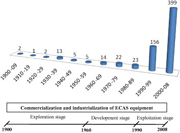
Number of ECAS patents per decade from 1900 to the first semester of 2008. The exploration (1900–1960), development (1960–1990) and exploitation (1990–2008) stages are defined in accordance with the worldwide industrialization and commercialization of ECAS.
Figure 2.
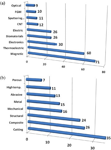
Number of published ECAS patents from 1900 to 2008 applied to (a) functional and (b) structural materials; the large number of industrial applications underlines the wide flexibility of ECAS.
According to the open literature [1, 2], the ECAS technology was pioneered by Duval d'Adrian [3] in 1922. However, the present review attributes to Bloxam [4, 5] in 1906 the first patent on pure direct current (dc) resistance sintering (RS). Thereafter, Taylor [6–8] developed the first resistive sintering process combining a capacitor bank, transformers and special switching devices. This originated the so-called electric discharge compaction (Edc) [9].
The progress of ECAS technology, however, was rather discontinuous as shown in figure 1. Its main driving force was initially motivated by the current industrial needs. Prior discouraging results were attributed to both the lack of fundamental understanding of basic principles and to poor devices (i.e. energy sources, capacitor switches, controlling systems, etc). These factors initially hindered the industrial development although the inherent benefits and potential of ECAS were readily recognized. Indeed, very few successful applications were reported before 1989.
The patent published by Inoue [10] in 1966 added a solid backbone to the existing ECAS technology. It introduced unprecedented technological innovations with new basic sintering principles using different electric current waveforms, (i.e. low-frequency ac, high-frequency unidirectional ac and/or pulsed dc). These methods were combined in one sintering process named ‘Electric-discharge sintering’ (EDS) [10], also known as spark sintering (SS). Spark sintering employs a unidirectional pulsed dc or a unidirectional ac, eventually superimposed to a dc. This process inspired the development of the subsequent pulsed electric current sintering (PECS) methods, e.g. plasma assisted sintering (PAS) [11], spark plasma sintering (SPS) [12] and plasma pressure compaction® (P2C) [13].
The most recent Inoue's patents have been focused on the design of more efficient current sources as well as on the introduction of auxiliary/peripheral devices to increase the reproducibility and controllability of ECAS processes.
ECAS is today considered as a mature and viable manufacturing technology. This is shown by the increasing rate of published journal papers and comprehensive reviews [1, 2]. About 2000 papers were published from 1970 to 2006 on SPS (see also figure 2 in [14], and figure 1 in [1]). The number of published papers started to grow exponentially from the early 1990s. In figure 1, this period corresponds to the exploitation stage of ECAS. Similarly, the number of annual international conferences, workshops and specialized symposia increased worldwide—US-ARO ’89, US ARO ’99, Pacrim, Sintering, SPS Forum and NEDO 2000, to mention a few.
The purpose of this work is to examine the evolution of ECAS technologies, from basic principles to devices and methods, by surveying relevant patents published in the past century. ECAS technologies are first categorized in terms of processing features and sintered materials. The basic concepts, features and definitions are outlined in accordance with the scientific and patent literature. The most relevant claims, taken from a subset of 119 (out of 642) patents on ECAS methods and apparatuses, are described in detail.
We assume the overall ECAS technology as consisting of a basic ECAS (section 2) and one or more auxiliary devices and peripheral units (section 3). Typically, a basic ECAS embodies the essential structure of an electrically assisted sintering apparatus.
Depending on the discharge time, a basic ECAS is classified into two classes, i.e. fast (section 2.2) and ultrafast ECAS (section 2.3). Figure 3 sketches the relevant milestones in the evolution of ECAS technology over the past century.
Figure 3.
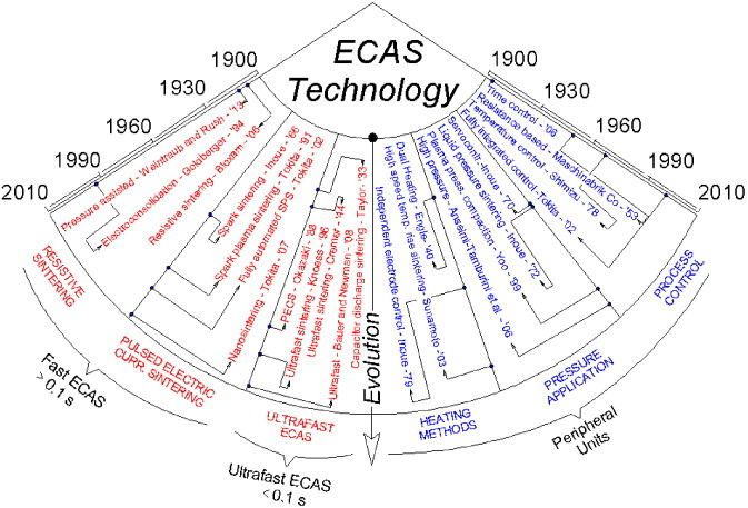
Diagram tracing the evolution of ECAS technology over the past 110 years. The main patents corresponding to milestones in basic ECAS and peripheral units, are specified on the left- and right-hand sides, respectively.
Basic ECAS apparatuses and methods
Fundamentals
ECAS [1, 15] is a class of consolidation methods in which mechanical pressure is combined with electric and thermal fields to enhance interparticle bonding and densification. The starting materials can be in the form of either powders or green compacts. The primary purpose of imposed electric currents is to provide the required amount of resistive heat. Moreover, electric currents may additionally enhance powder sintering by activating one or more concurring mechanisms, such as surface oxide removal, electromigration and electroplasticity [2]. The overall resistive heat consists of a localized and massive heat. The former is concentrated at particle interfaces and serves to bond particles with each other. The latter promotes plastic deformation upon sintering.
Basic ECAS versus HP: heating methods
Essentially, basic ECAS exploits the same punch/die system concept as the more familiar hot pressing (HP) process (figure 4). A powder or green compact is placed in the die and subsequently pressed between two counter-sliding punches. Mechanical loading is normally uniaxial. It is well documented that in the HP process the powder mainly densifies owing to a combination of thermal and pressure effects.
Figure 4.
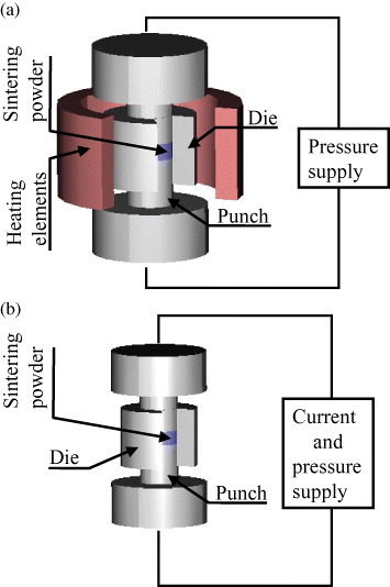
Schematic of sintering process: (a) hot pressing and (b) ECAS.
However, ECAS and HP differ significantly in the heating mode (figure 4). Specifically, in HP an array of heating elements indirectly heats the punch/powder/die assembly by radiation and eventually by convection and/or conduction (figure 4(a)). The powder heating rate is controlled by the rate of radiation and/or convection and conduction. Conversely, in ECAS (figure 4(b)), the punches transfer the electricity and Joule heat directly to the powder. As the supplied current density can be very large, the heating rate in the powder can approach 106 K s−1 (see ultrafast ECAS in section 2.3.2). This heating rate is much higher than 80 °C min−1 for the HP process [16]. Thus, the ECAS sintering time can be lowered and the production rate increased.
Classification
As indicated in table 1, basic ECAS apparatuses can be primarily classified with respect to the discharge time, repetition frequency of the pulse trains, electric current density and waveform. Classification based on discharge time is more practical. Conventionally, 0.1 s discharge time can be assumed as the threshold between fast and ultrafast ECAS. However, confusion should be avoided between fast termed herein and the FAST acronym (field activated/assisted sintering technique, see section 2.1.3) frequently encountered in the scientific literature. Here, fast simply refers to either a high processing rate or a low processing time.
Table 1.
ECAS process classification. Fast ECAS is characterized by a discharge time of minute order and includes resistance sintering (RS) and pulsed electric current Sintering (PECS). The discharge time of ultrafast ECAS is below 0.1 s. Current waveforms, processed materials and the main operating parameters are also given. For the acronyms refer to the list of ECAS abbreviations.
| Typical current waveform | Abbreviations of sintering process | Frequency; pulse energy; discharge time | Patent; year; inventor reference | Sintered materials | ||||||||
|---|---|---|---|---|---|---|---|---|---|---|---|---|
| Discharge time >0.1 s | Imposed current density <1 kA cm−2 | |||||||||||
| Fast | RS |  |
RS | dc current; | Bloxam | Electrically | ||||||
| ECAS | Resistance | Electro- | not applicable; | US1906 | conductive and | |||||||
| sintering | consolidation | >0.1 s | [4, 5] | nonconductive | ||||||||
| (i.e. metals, | ||||||||||||
| PECS |  |
EDS SDS, | 102–108 Hz; | Inoue | ceramics, | |||||||
| Pulsed electric | SS Evolution: | ≈10 J | US1966–67 | composites and | ||||||||
| current sintering | PECS SPS | >0.1 s | [10, 32, 73] | polymers) | ||||||||
| PAS P2C® | ||||||||||||
| Discharge time <10−1 s | Imposed current density >10 kA cm−2 | |||||||||||
| Ultrafast | Ultrafast |  |
EDC | Single pulse | Taylor | Electrically | ||||||
| ECAS | ECAS | HEHR | 1–100 Hz, | GB1932 [6] | conductive | |||||||
| CDS | About 101 KJ | TaylorUS1933 | (i.e. metals | |||||||||
| <0.1 s | [7, 8] | and cermets) | ||||||||||
According to a recent review [1], fast ECAS may take more than 50 different names. The inherent classification, made with reference to the electric current waveform and apparatuses [1], focused on scientific papers rather than on original patents. This number is too large and inappropriate for capturing the essential features of the methods and apparatuses. A revised classification based on original patents on fast ECAS methods and apparatuses is given in section 2.
The distinction between fast and ultrafast points out the differences in the hardware employed in basic ECAS (e.g. current sources) as well as its features (e.g. current density and waveform, response time, control unit and loading method). In fast ECAS, usual discharge time, current density and voltage are on the order of minutes, up to 1 kA cm−2 and tens of volts, respectively (see table 1).
Fast ECAS, in turn, can be classified with respect to the current waveform. RS and PECS, the two main processes of fast ECAS family, employ direct and pulsed current waveform, respectively. Fast ECAS is performed using with either an electrically conductive or insulating powder. In the latter case, heat is indirectly conducted to the powder from the surrounding die and the sliding punches (figure 4(b)).
Ultrafast ECAS typically combines relatively high pressure and a very high electric current density (≽10 kA cm−2). The voltage may range from a few volts to kilovolts. Current is typically generated by one or more capacitors which are discharged in less than 0.1 s. Ultrafast ECAS mainly applies to electrically conductive powders. Joule heating is rapidly generated across the powder. Ultrafast ECAS (see section 2.3.2) is also known as electric discharge compaction (EDC) [17–19], high energy high rate (HEHR) [20], capacitor discharge sintering (CDS) [21] and flash sintering (FS) [22].
ECAS versus FAST
Attempts were made in the past to group various ECAS methods under the unifying family of field activated sintering techniques (FAST) [16]. The FAST acronym is widely used in the research and industrial communities. In this work we attribute to FAST a large class of sintering processes of which ECAS is a subclass. The ‘Field’ term in FAST acronym can be then referred to virtually any field such as mechanical, electric, gravitational or electromagnetic. For instance, the well-known processes such as microwave [23], millimeter-wave [24] and plasma [25] sintering, can be considered as FAST-type rather than ECAS-type. Moreover, Magnepress™ dynamic magnetic compaction (DMC) [26, 27], which exploits a pulsed electric current to augment the compaction force, is a FAST-type rather than an ECAS-type process since neither the electric current nor the dissipated heat (Joule effect) directly flows across the powder.
Benefits
The established advantages of ECAS are: (a) low power consumption (approximately one-fifth of HP) [28], (b) the absence of sintering aids, (c) control of the thermal gradient (for functional graded materials (FGMs) [29–31], (d) selective control of the density in specified regions [32], (e) accurate control of the porosity [33], (f) single step sintering-bonding [8, 34], (g) particle surface cleaning, (h) high heating rate and (i) near-net-shape capability (table 2). The short sintering time is particularly suitable for: (a) preserving initial powder grain size or nanostructure [35, 36], (b) consolidating amorphous materials [37–39], (c) improving bonding strength between particles and (d) controlling phase reactions or decomposition (in the case of composites) [40]. ECASed materials often exhibit improved physical and mechanical properties compared with those obtained by conventional methods. Noteworthy features resulting from ECAS include superplastic behaviour of ultrafine ceramics [41], increased permittivity of ferroelectric materials [42–44], improved magnetic properties of magnetic materials [38, 45, 46], enhanced product-scale bonding [47], augmented thermoelectric properties [48, 49], superior mechanical properties and reduced impurities segregation at grain boundaries [50–52].
Table 2.
Patents on near-net-shape capability of ECAS.
| Product shape | Reference |
|---|---|
| Hollow parts | [53] |
| Nozzle | [54] |
| Concentric circular functionally gradient material | [55] |
| Annular magnet | [56] |
| Die for forming glass lens | [57] |
| Automotive piston | [58] |
| Die for wire drawing | [59] |
| Complex parts (e.g. scroll-shaped) made of Al–Si | [60] |
| Friction element for disc brake | [61] |
Processing parameters
The heating rate acts as a new important sintering parameter (figure 5) that further extends the potentials of ECAS. Moreover, the chamber atmosphere, along with the parameters of heating rate and mechanical loading can be adjusted to optimize ECAS or to tailor the material microstructure.
Figure 5.
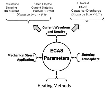
Main ECAS parameters: current density, current waveform, heating method, mechanical stress field and chamber atmosphere.
The electric supply is the primary source of heating of the punches, die and sintering powder. The current density and waveform (see section 2.2) determine the type of current source. A strong nonlinear interaction exists between heat flow and current through the material properties (e.g. electrical resistivity, thermal conductivity, density and specific heat).
The system geometry is another crucial factor affecting the heating method (section 3.3). In turn, the temperature distribution affects the homogeneity of the final microstructure. In the absence of suitable auxiliary or heating control devices, the product shape is restricted to simple geometries and the product diameter is typically below 5 cm [52].
The mode of mechanical loading (section 3.5) is also a crucial factor. It can be either static, periodic or impulsive. Depending on the loading mode, very different stress states, such as shear, uniaxial or pseudo-isostatic can be induced in the powder.
It is well known that ECAS can be operated under various atmospheres (section 3.8), such as vacuum, inert gas or air. Inadequate atmospheres or operating conditions may facilitate sparking whereas in ultrafast ECAS reduced chamber pressure may induce a glow discharge between particles [39].
Fast ECAS: apparatuses and methods
Exploration stage
Initially, ECAS apparatuses were limited by electric power, mechanical pressure and process control. Notwithstanding, the original fundamental ECAS principles reported in the early patents are still used in modern apparatuses.
Table 3 summarizes the first patents on fast ECAS, together with the most relevant operation conditions and the ECASed materials. According to the present ECAS patents survey, Bloxam [4, 5] is the pioneer of ECAS technology in 1906 (figure 6). The primary purpose of his inventions [4, 5] was the industrial scale production of incandescent lamps. A green body filament, consisting of either W or Mo particles, was sintered in vacuum by forcing a direct current to pass through them without exerting pressure. The current was particularly effective in reducing surface oxides. The emissivity of the incandescent filaments was sensibly increased.
Table 3.
Operating conditions described in early ECAS patents: (i) punch and die materials; (ii) applied pressure, voltage drop (between electrodes), current density, discharging time, sample diameter; (iii) chamber atmosphere and (iv) sintered materials.
| Inventor, nation year, reference | Processing condition and apparatus | Pressure, voltage, current, temperature, discharge time, diameter | Chamber atmosphere | Sintered materials |
|---|---|---|---|---|
| Bloxam, GB1906 [4, 5] | Pressureless sintering by current flow across the sample | 0, (ng), (ng), (ng), (ng), (ng) | Vacuum | Industrial scale production of W and Mo lamp filaments |
| Weintraub, US1913 [62] | Pressure and current sintering | (ng), 110 V, (ng), ≈2000, (ng), ≈2 cm | Vacuum | W, carbides and nitrides |
| Davis, GB1927 [63] | Die made of silica tube Punch made of steel (water cooled) | (ng), (ng), (ng), 1000 °C, <5 min, (ng) | Vacuum | Refractory materials |
| Sherwood, GB1931 [64] Sherwood, GB1933 [65] | Metallic punch and die Easily sintered parts Extraction by lubricants | 30/300 MPa, (ng), (ng), (ng), 30–120 s, (ng) | Inert/reducing atmosphere | Oilfree bearing material made of 89 wt% Cu, 10 wt% Sn and 1 wt% stearic acid |
| Taylor, GB1932 [6] Taylor, US1933 [7] | Die made of graphite or silica punch made of steel; | Assumed 100 MPa, (ng), (ng), 1000 °C; 1–2.5 s, ‘length greater than its diameter’ | Vacuum | 80–97 wt%; 3–20 wt% WC C |
| Hoyt US1932 [66] | Graphite die | 7 MPa, (ng), (ng), 1300–1450 °C, ‘about one to several minutes’, (ng) | Inert/reducing atmosphere | WC 87 wt% Co 13 wt%, from elemental W and C powders |
| Thomson Ltd, GB1935 [68] | Die made of graphite Plungers made of graphite or Mo | (ng), (ng), (ng), 1000 °C, <30 s, 2 cm | (ng) | Abrasive wheels with 10–20 wt% diamond, 3–20 wt% Co and WC |
| Kratky, US1937 [70] | Die made of graphite Punch made of W | Impact loading, 4 V, 800 A, (ng), few minutes, (ng) | Vacuum | Hard bodies especially WC cermets, HSS |
| Willey, US1937 [144] Willey, US1938 [145] | Spot welding machine Die made of graphite Punch made of Mo | 70 MPa, (ng), (ng), (ng), >4 min, (ng) | Air | Diamond-embedded abrading tool, WC and Ni or Co |
| Engle, US1940 [71] | Hybrid heating from inside/outside Homogenous temp. distribution Punch and die made of graphite | (ng), 3–12 V, >3000 A, (ng), >1350 °C, 7.5 cm | Controllable | Cermets |
| Cremer, US1944 [87] | Electrically insulated die Metallic punch | 150–350 MPa, 5–20 V, repetition of 20 kA (pulsed), 1/30 s, 0.7 cm | Air | Cu, Au, Al and other metals, densification time <1/30 s |
| Ross, US1945 [72] | Automatic sintering machine Mica insulating die Metallic punch | Impulsive loading >500 MPa, (ng), (ng), (ng), (ng), (ng) | Air | Steel, cermets |
(ng), not given in the patent.
Figure 6.
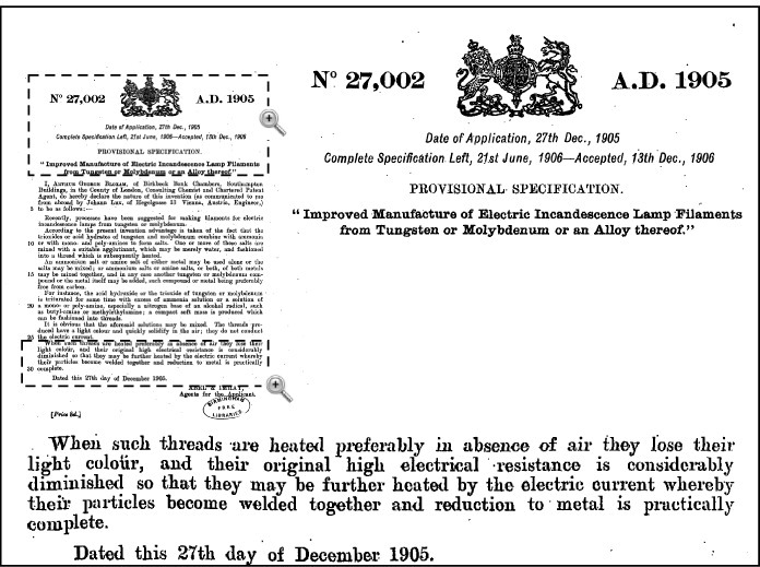
Front page of the first patent on ECAS technology by Bloxam in 1906 [4].
In 1913, Weintraub and Rush patented [62] a new sintering method which simultaneously combined pressure and an electric current. The benefits of this method were proved for the sintering of refractory metals as well as conductive carbide/nitride powders. This invention can be considered as the precursor of modern fast ECAS. As shown in figure 7 (from the original patent), the starting elemental powders (1) (e.g. boron–carbon or silicon–carbon) were placed in a boron nitride electrically insulating tube (2) inside a metallic tube (3). A graphite punch/electrode (5, 6), connected to a power generator, exerted a uniaxial pressure through the weight of an intermediate plate (9). Other mechanical means such as screw or hydraulic press could be also used. A high dc voltage was first imposed to overcome the high initial electric resistivity of the powder. This voltage was then progressively reduced as the powder resistance decreased by shifting the connection from a 15 kV to a 500 V (or 110 V) power source. The estimated sintering temperature was approximately 2000 °C.
Figure 7.
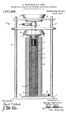
Sintering apparatus based on the original scheme patented by Weintraub and Rush [62] in 1913, which simultaneously applied direct Joule heat and pressure.
In 1922, Duval D'Adrian [3] developed a three-step method to sinter electrically insulating powders such as zirconia, thoria and tantalia. His invention was used to produce insulating tubes, crucibles, blocks and muffles. The steps were: (i) mixing the oxide powder with a binder and moulding them into a desired shape, (ii) complete drying of the moulded article and preheating in a conventional furnace to make the oxide electrically conductive, (iii) direct resistive sintering to 2500 °C (estimated) while applying pressure using a pair of carbon electrodes.
Fast ECAS received special attention between 1920 and 1940. Major efforts were devoted to fully densifying difficult-to-sinter materials such as high melting point borides and carbides. A strong industrial need at the time was the production of WC–Co-based cutting tools and diamond based grinding wheels.
In 1927, Davis developed an RS method [63] for refractory powders. He paid special attention to increasing the sintering rate to less than a few minutes. His successful fast sintering led to a significant technological simplification since high vacuum sintering chambers could be avoided. A silica tube was used as a die and two water-cooled steel electrodes served as pressure punches.
In the early 1930s, the production of self-lubricating bearings and bushings was strongly pushed by industry. In 1931 [64] and 1933 [65] Sherwood patented an RS method to manufacture porous oil-impregnated metal bodies as self-lubricating materials (i.e. 95 wt% iron powder with 5 wt% stearic acid). Sherwood's process was conducted in a reducing or inert atmosphere. The imposed pressure ranged from 30 to 300 MPa and the sintering time was between 30 and 120 s. The final products exhibited high strength combined with superior wear resistance and easy machinability.
Hoyt [66] and Gilson [67], both working for General Electric Co., New York, patented two RS methods to fully densify WC–Co powder in a few minutes by simultaneously applying electric discharge heat and pressure. The imposed pressure was approximately 7 MPa, the temperature ranged from 1300 to 1450 °C and the sintering time was approximately 5 min. These inventions simplified the manufacture of dense WC–Co sintered products, making them cost-effective. Gilson's invention, unlike Hoyt's invention, involved the concurrent reactive synthesis and sintering of WC from elemental W and C powders. This basic concept was subsequently used for sintering WC–Co products.
In 1935, Thomson Houston Co., Ltd. patented [68] a method for sinter-bonding grinding wheels (12.5 mm in diameter) consisting of an abrading outer ring bonded to a metallic core. The outer ring was composed of a powder mixture containing diamond (10–20 wt%) embedded in WC–Co (3–20 wt%). The peak sintering temperature and discharge time were approximately 1300 °C and 30 s, respectively. According to the original patent [68] (figure 8), the mold was clamped between water-cooled electrodes (10, 11). The powder mixture (14) was placed in the annular space delimited by the metal disc (5), the punch (7) and the die (2). The grinding wheel was mounted on a (15) supporting shaft (figures 8(b) and (c)). A combination of electric current, heat and pressure allowed both the sintering and welding of the outer ring to the metal disc. This process paved the way for new industrial applications of ECAS since it effectively combined sintering with bonding.
Figure 8.
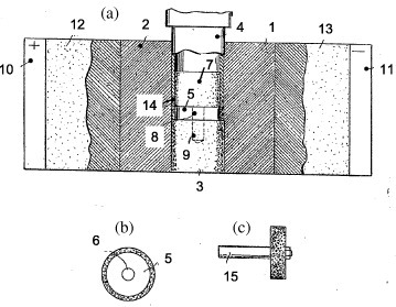
Sintering of metallic grinding wheels based on the original scheme patented by Thomson Houston Co., Ltd, in 1935 [68]: (a) cross section of the apparatus and (b) front and (c) side views of metallic the wheel. The working surface of the wheel included 10–20 wt% diamond powder embedded in WC–Co matrix.
In 1939, Gillet and Dayton [69] developed an RS method suited for oil-free bronze (Cu-10 wt% Sn-10 wt% Pb) rods or bushings. The applied current was about 1770 A and the sintering time ranged from 8 to 10 s.
The urgent demand for cutting tools and wear resistant parts significantly promoted the development of new sintering apparatuses. In 1937, Kratky patented [70] a fast ECAS method assisted by impact loading. This invention was applied to the manufacture of carbide and nitride cutting tools. The current (probably dc) was approximately 800 A which corresponded to a voltage drop of 4 V (figure 9(a)). As the die and powder approached the desired temperature, the powder was suddenly pressed by impact loading. Electrodes were water cooled to avoid overheating.
Figure 9.
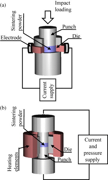
Sintering apparatuses based on (a) Kratky's impact loading system and (b) Engle's supplementary heating method, where powders are heated simultaneously by the Joule effect and by a die surrounding furnace (adapted from [70, 71], respectively).
In 1940, Engle invented [71] a sintering method to minimize the radial temperature and density gradients. The radial temperature uniformity was enhanced by combining a die surrounding furnace with direct resistive heating (figure 9(b)).
The first automated ECAS apparatus was developed in 1945 by Ross [72] and applied to the sintering of metallic powders under repeated electric discharges. This apparatus included: (i) an on-line control unit for weighing the powder, (ii) a precompression device, (iii) the ECAS system and (iv) a product ejection device. The process employed repeated high-current/low-voltage pulse discharges superimposed to pressing pulses trains. Current discharge and pressure loading were synchronized to achieve optimum interparticle heating. The repetition of current and pressure pulses enhanced the progressive deformation of particles. Pressure pulses were beneficial for full densification and current pulses improved heating control.
Development and exploitation stages of ECAS
Fast ECAS technology flourished in 1966–19 thanks to Inoue who patented the revolutionary ‘Electric-discharge sintering’ [10], commonly known as spark sintering (SS). Inoue filed patents were by in 1966 [10, 73] and 1967 [32]. He pioneered the pulsed electric current sintering (PECS) methods and reconsidered the pressure application method and the current waveforms. Inoue's invention [32] specifically states that ‘… this method is based upon the totally surprising discovery that, contrary to the weight of earlier beliefs that elevated pressures are required to carry out an effective sintering operation, relatively low mechanical pressures can be employed when spark discharge is used. The electric spark, which advantageously possesses a power of the order of hundreds and even thousands of Joules, forces the particles into bonding contact with a pressure even greater than that attainable heretofore by mechanical means even when the particles are in relatively light contact. In fact, such light contact is necessary to the development of the necessary spark which also provides sufficient heat to cause the particles to bond together with great strength …’ ‘… Since the sintering action occurs immediately upon the space discharge, the completed body can be formed in a matter of seconds as compared with earlier methods requiring tens of minutes and even hours to effect complete sintering …’.
In 1966, Inoue patented the SS apparatus [73], which was designed to sinter conductive particles (admixed with no more than 20 wt% nonconductive powder). The power source supplied periodic (capacitive) current pulses (2.5 ms interval), eventually superimposed onto a direct current to enhance interparticle spark discharge. Figure 10 shows the schematic of an adapted concept taken from the original electric circuit of the ‘Impulsive spark discharge’ method [73]. The powder was poured into a meld cavity and compressed between the electric punches. The current frequency was determined by the time constant of a resistor (1) and a capacitor bank (2). The latter was periodically charged from the battery (3) and discharged across the primary transformer winding (4) when the switch (5) was closed. The pulsed current, eventually superimposed to a battery dc (6), was transmitted to the electric punches to generate the ‘Impulsive spark discharge’ sintering.
Figure 10.
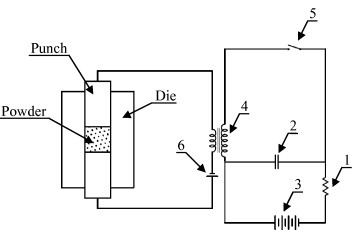
Schematic of the impulsive spark discharge sintering patented by Inoue in 1967 (adapted from [32]).
In the same year, Inoue patented a method and apparatus of a new type of spark sintering [10] based on the combination of a ‘… unidirectional electric current, a low-frequency alternating current and a high-frequency alternating current superimposed upon said unidirectional electric current while effecting an impulsive spark discharge between said electrodes, compressing said mass and through the compressed mass to bond adjacent particles together …’.
Another relevant point regarding Inoue's patent [32] concerned the application of a single or a succession of ‘Impulsive electric currents’ with/without the superimposition or the combination of periodic currents. However, the current waveform was not specified. Originally the concept of ‘Impulsive’ current was strictly associated to the occurrence of ‘… spark discharge to fuse said conductive and non conductive elements together …’ or to the formation of conducting bridges.
Essentially, Inoue's method [32] performed two specific functions: (a) bulk resistive heating at a low frequency (100 Hz) and/or direct current and (b) spark discharge at a high frequency (100 MHz). The application of low pressure and high frequency impulsive current was particularly effective in the first stage of sintering. Indeed, it promoted sparks and rapid local heating at particle contact interfaces due to the high initial contact resistance. As a result, powder densification was promoted by the combination of bulk resistive heating and pressure induced plastic deformation. This was a new sintering concept, in contrast to the current sintering practice, for which the high pressure minimized the interparticle contact resistance and maximized powder compaction. Spark sintered bodies were fully densified using a two stage pressure cycle: (a) low pressure to promote interparticle heating (<10 MPa) and (b) relatively high pressure to enhance powder densification. It was claimed that the increased pressure and the switching off of the power were also favourable for enhancing densification. In the case of cobalt powder (Ø 15 mm, 5 mm thick), spark sintering led to a final specific gravity of 8.8 g cm−3 after discharge at rate of 50 J pulse−1 for 25 s with a pulse frequency of 20 MHz, two power offs and a pressure of up to 50 MPa.
Moreover, Inoue's patent [32] claimed:
the relative axial vibration of at least one electrode
selective densification in certain portions of the powder mass (by embedding highly conductive members) to concentrated the current flow
continuous sintering.
Inoue's patents were industrially applied by Lockheed Missiles & Space Co., which acquired the worldwide rights (excluding Japan) from the Japanese inventor [74]. As reported by Boesel et al [75] the machines available at Lockheed Missiles & Space Co. in 1969 were powerful in terms of maximum current (70 kA) and pressing force (100 t). For instance, large beryllium Minuteman missile rings (15 kg weight) were sintered in 45 min [74–77]. Typical operating parameters were 5–10 V voltage, about 230 A cm−2 current density and 3.5–14 MPa pressure. The electric current split was typically 25% ac and 75% dc. Spark sintering provided higher densities than those attainable using conventional powder metallurgy. Spark sintering was applied to cylindrical parts (Ø 7–10 cm, 1–5 cm thick, about 230 g weight) made of materials such as Ti, Al, Co, Inconel, W, Mo and WC and composites such as beryllium-stiffened titanium.
Despite the profound interest generated, Inoue's patents were not widely used at that time. Perhaps, the high cost of equipment, the lack of repeatability or the low sintering efficiency may have discouraged their development. Only a few machines were commercialized in America by Lockheed Missiles & Space Co. [75].
In the late 1980s Inoue's patents [10, 73] expired, and various companies started to manufacture PECS machines based on Inoue's inventions [78]. Since then, the number of PECS applications has been extended further. Between the end of 1980s and the early 1990s, Japanese Sodick Ltd, developed PECS to achieve the plasma activated sintering (PAS) technology. Matsushita Inc. used PAS units to produce hard magnets [79]. However, the available commercial apparatuses were limited in terms of pressing force (5 t) and electric source (below 800 A, 50 V).
SPS and PAS slightly differed in the electric supply, e.g. only pulsed dc in the former and pulsed dc below 1000 s followed by a dc in the latter.
In the early 1990s, Sumitomo Coal Mining Co. Ltd commercialized new SPS apparatuses (2–20 kA dc pulse generators, 10–100 t load cells) [12, 80]. In 2005, the same company became a joint venture with the name of SPS Syntex Inc. Japan (Sumitomo/SPSS).
As reported by Orrù et al [1], most of the reported fast ECAS systems employ pulsed dc. This is mainly due to the worldwide commercialization of Sumitomo/SPSS apparatuses. Sumitomo/SPSS current waveforms are shown in figures 11(a)–(c). The pulses span over 3.3 ms, whereas the on time and the off time may range between 3 and 300 and between 3 and 30 ms, respectively. The most commonly used duty cycle is 12 pulses on and 2 pulses off (figure 11(c)). The current pulse range of commercially available Sumitomo/SPSS apparatuses has remained unchanged since 1990. However, in 1996–97 Sumitomo/SPSS introduced a new inverter-type SPS pulse generator, where the pulse duration (or off time) ranged from 10 to 500 ms as shown in figures 11(d)–(f).
Figure 11.
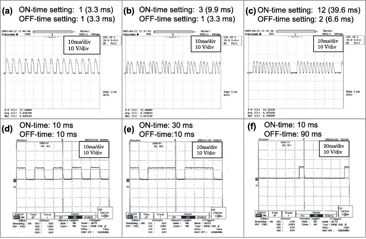
Current waveforms from two basic SPS pulse generators and three duty cycles. Panels (a)–(c) are for a thyristor-type pulse generator with a pulse duration of 3.3 ms (since 1989) [12, 80]. Panels (d)–(f) are for an inverter-type pulse generator (1996–1997) (courtesy of Sumitomo/SPSS, Japan).
More recent SPS developments have concerned process automation. Four types of semi- or fully automated SPS systems have been patented: multihead [81], tunnel [82], rotary table [83] and shuttle [84] systems. Each apparatus serves specific industrial applications. All apparatuses are based on the application of electrification heat and pressure.
The fully automated tunnel SPS system was patented in 2002 by Tokita [82]. This invention was successfully employed for the mass production of WC–Co and WC–Co/Ni FGMs. As shown in figure 12, the invention provided a method and a hardware system to automatically fill the powders into a meld and to automatically sinter the powder. In addition, the automatic loading of different powders allowed the production of layered FGM products.
Figure 12.
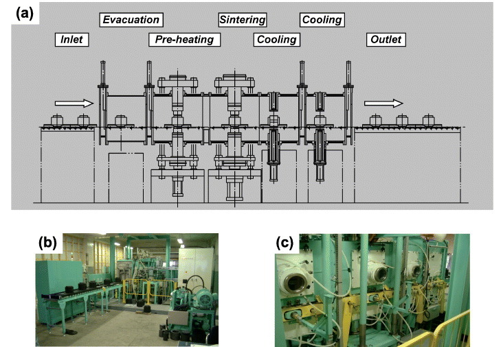
SPS tunnel-type automated machine [82]: (a) layout, (b) machine inlet and (c) preheating/sintering/cooling systems (courtesy of Sumitomo/SPSS, Japan).
In 2004, the automated shuttle-type SPS machine [84] enabled the continuous/high speed production of low melting point metallic compacts without any protective atmosphere.
The automated multihead SPS system [81] is shown in figure 13. It includes a robot (1) which automatically loads and unloads the working dies inside the SPS sintering machine (2). In 2002, Tokita and Nakagawa patented the rotary table [83] SPS system (figure 14). The dies were intermittently filled with powders and then sintered. The degree of automation of the SPS multihead [81] and rotary table [83] systems was further increased using the automatic powder filling mechanism described in Tokita's patent [85].
Figure 13.
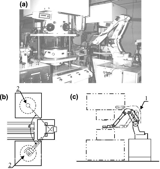
(a) Photograph of a fully automated multi-head SPS system [81]. In (b) and (c), the SPS system is equipped with a robot (1) that handles loads and unloads of the powder in the die (2) (courtesy of Sumitomo/SPSS, Japan).
Figure 14.
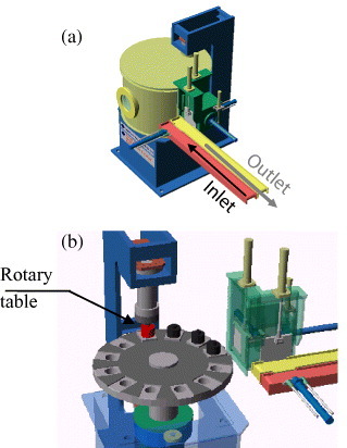
Rotary-table system [83] (courtesy of Sumitomo/SPSS, Japan).
The latest patent filed by Tokita et al [86] in 2007 addressed the nanoprecision sintering. Nanosized powders are handled in an inert atmosphere to prevent contamination and/or oxidation. At least one preprocessing chamber, commonly connected to the main SPS chamber, was designed to operate under a protective atmosphere.
Ultrafast ECAS
Physical principles
Ultrafast ECAS typically employs either one or up to three repeated (capacitor) discharges. As shown in table 1, each discharge lasts less than 0.1 s. The current pulse density can be on the order of 10 kA cm−2. In the scientific literature, ultrafast ECAS is generally referred to as electric discharge compaction (EDC) [17, 19, 39]. However, this term is not commonly used in published patents.
Although both fast and ultrafast ECAS can be classified as resistive sintering processes, they are basically different. In fast ECAS, Joule heating is provided to the punches, die and powder. Conversely, in ultrafast ECAS, Joule heating is mainly localized in the powder compact.
In ultrafast ECAS, the current pulse lasts from 10−5 to 10−1 s. Depending on the hardware, the overall cooling time may be within seconds. Ultrafast ECAS combines a single current pulse with a relatively high mechanical pressure (up to GPa order). Punch materials, such as copper–beryllium alloys, tungsten and molybdenum, exhibit both high mechanical resistance and electrical conductivity. The die materials can be either electrically insulating (glass, bakelite or alumina, etc) or conductive (graphite, steel, etc). Further details on the punch and die materials are given in section 3.6.
A typical equivalent electric circuit of an ultrafast ECAS apparatus is shown in figure 15. The electrically conductive powder acts as a short circuit resistance. The discharge time and waveform are affected by impedance L, resistance R and capacitance C of the apparatus circuit (table 1). The capacitors are preliminarily charged by the electric generator. A voltage (tens to thousands of volts) is imposed at the ends of the punches. Most of the electric energy is released within the first time period (table 1). Heat is rapidly generated by the Joule effect at contact–particle interfaces.
Figure 15.
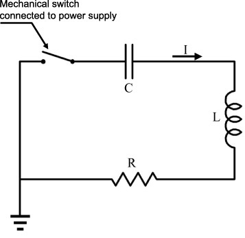
Equivalent electric circuit of EDC machine (adapted from [39]).
Because of the rapid heating and cooling, ultrafast ECAS may be carried out in air with its inherent advantages of limited grain growth and hardware simplicity, controllability and cost.
Patents on ultrafast ECAS
Ultrafast ECAS was pioneered by Taylor [7] in 1933. The patent was applied to the sintering of WC 3–20 wt% Co powders at 1000 °C. Similar patents were previously proposed by Gilson [67] and Hoyt [66]. The process developed by Taylor differed from those of Hoyt and Gilson in that (a) sintering was carried out in vacuum or under a reducing atmosphere, (b) powders were confined in an electrically insulating die and (c) discharge was induced by a capacitor. The condenser was connected to 2500 volts dc through a 200 ohm resistor. Firstly, the condenser discharge reduced the electrical resistance of the powder; secondly, a low voltage current was applied to the sintering body which was connected to a commercially available ac source through a transformer. Taylor clearly underlined the importance of rapid sintering to prevent grain coarsening and to improve the final properties of the sintered powder.
In 1933, Taylor improved and extended his invention to the sintering-bonding of dissimilar conducting materials [8]. The joints and intermediate powders were placed in an electrically insulating meld and sintered by an electric discharge for a fraction of a second.
In 1944, Cremer developed a new apparatus based on a modified spot welding machine (i.e. Thomson-Gibbs K-18-40) [87] operating with 20 kA pulsed current (60 Hz, 5–20 V) and 60–120 MPa. The die material used depended on the imposed pressure. Insulating materials (e.g. bakelite, high strength dielectric plastics) were employed at low pressures whereas metallic materials with an insulating lining were used at high pressures. Brass and copper powders, packed into samples of 0.6 cm diameter, were fully sintered by 1 or 2 current pulses of 70 kA cm−2 (30 ms each) with no evidence of grain coarsening. As diffusion during sintering was markedly suppressed, the bearing properties of tin- and copper-based materials were improved. Cremer's method [87] was also applied to refractory materials. The undesired melting of the punches and powders was prevented by a series of discharges separated by 1 s or longer.
As shown in table 4, the recently published ultrafast ECAS patents mainly differ in applied pressure, voltage and current density.
Table 4.
Recent ultrafast ECAS patents: inventors, controlling parameters (applied pressure, discharge time, voltage drop and imposed current) and sintered materials.
| Inventor, nation year, reference | Pressure, discharge time, voltage, current densitya | Sintered materials |
|---|---|---|
| Cremer, US1944 [87] | ≈100 MPa, 10 ms, 5–20 V ≈60 kA cm−2 | Cu, Al, brass |
| Parker, US1968 [88] | 10 MPa, 1 ms, (ng) >150 kA cm−2, 2000 J cm−3 | Ti, Fe |
| Hetherington, US1969 [90] | 120 MPa, (ng), 30 kV, (ng) | Porous materials particularly Ta |
| Okazaki, US1990 [39] | 10 MPa, 10–500 μs >3 kV, >50 kA cm−2 | Al–Fe–V, Ni, Ti, Ta |
| Knoess, US1996 [93] | 300–700 MPa 0.05–50 ms <30 V, 100 kA cm−2 | Fe, Cu |
| Bauer, US2008 [94] | 400–700 MPa, 0.1–1s 7 V, <10 kA cm−2 | Steel |
aReference value as given in the patent; (ng) =not given in the patent.
In 1968, Parker [88] patented a sintering method employing high energy short current pulses (i.e. a single pulse of at least 150 kA cm−3 for more than 1 ms) and pressure was applied by a pressure transformer device [89]. The latter transformed the electric current into a mechanical pressure. Pure iron powder was placed in a Teflon split ring (6 mm inner diameter) and compressed between copper electrodes. Pressure was automatically increased from 13 to 20 MPa within 1 ms. The specific energy required to full sinter the iron powder was 2000 J cm−3.
In 1969, Hetherington [90] employed a capacitor bank to produce uniform porous tantalum bodies from metal particles as follows: (i) pressure application on the order of 120 MPa, (ii) current discharge at 30 kV and (iii) furnace sintering to enhance the mechanical properties with no further densification.
In 1990, the high voltage capacitor discharge method was successfully re-launched by Okazaki for sintering metals [39], refractory metals [91] and superconducting materials [92]. The pressure was about 10 MPa and current density was larger than 50 kA cm−2 over a period of 10–500 μs (with a voltage greater than 3 kV). This current was effective in disrupting surface oxide layers around particles. According to the patent [39], solid compacts (5×50×2.5 mm−3) of sintered Al–Fe–V powders reached up to 95% of the bulk density using a ceramic mold at an operating pressure of 5.6–7.8 MPa and a current density of 150 kA cm−2 (5 kV) in 100 μs.
Knoess and Schlemmer in 1996 [93] and Bauer and Newman in 2008 [94], independently patented an ultrafast sintering process operating under low voltage discharges (<50 V) and pressures (up to 1 GPa). They filled an electrically insulating and nonmagnetic meld with conductive powders or pre-compacted bodies. Alternatively, an electrically conductive die internally coated with an insulating film could be used. High densification (above 96%) was achieved by simultaneous application of a high pressure (300–700 MPa) and 1 to 3 current pulses under an imposed current of 100 kA (10 V) in just 2 or 3 ms.
The punches and die were made of molybdenum alloys and high strength ceramics, respectively. As reported in the patent [93], an iron powder disc of 10 mm diameter and 10 mm height was precompressed under 500 MPa. Subsequently, a single current pulse of 86 kA (110 kA cm−2) peak current and a 10 V voltage was discharged in 2.25 ms. The final relative density was as high as 99.2%. As the sintered parts exhibited a mechanical strength comparable to that obtained by conventional sintering methods, they were completed in a continuous sintering furnace. The resulting compacts possessed high strength, dimensional stability and minimal residual porosity.
Bauer and Newman's sintering method [94], patented in 2008, is a hybrid method. It can be classified (table 1) as a fast ECAS, since its discharge time is above 0.1 s, but also as an ultrafast ECAS since it exhibits the cold die wall feature. According to their patent Bauer and Newman, employed a pressure of 400–700 MPa, a current density below 10 kA cm−2 and a sintering time of 0.1–1 s depending on the powder. Unlike the ultrafast ECAS patents listed in table 4, this process employed either a dc or an ac source. For instance, pure iron powder (33 g) was sintered to a final density of 97.58% using 300 MPa pressure, 26 kA (≈10 kA cm−2) peak current, 7.5 V voltage and 1 s discharge time.
In 2003, a noncommercial apparatus has been developed at Warsaw University of Technology named pulsed plasma sintering (PPS) [95, 96]. This process, which is carried out in minutes, also employs high current pulses from a capacitor bank. The maximum current is 60 kA (10 kV). Each impulse lasts about 50–600 ms. The repetition frequency is about 1 pulse per second and the off times are relatively long.
Peripheral ECAS units
General features
In the past century the simultaneous development of basic ECAS apparatuses and peripheral units was fundamental in overcoming intrinsic technological limitations and in optimizing ECAS processes with respect to (a) product size, (b) microstructure homogeneity, particularly for large bodies, (c) process reproducibility and (d) processing parameters. Reproducibility and homogeneity were particularly critical issues for ECAS industrialization. Early patents assumed a sample diameter of below 5 cm, although the product size (table 3) was not always disclosed (i.e. Gilson's, Hoyt's and Taylor's patents). Nonuniform densification was mainly attributed to temperature gradients in the punch/die/sample assembly. The industrial success of modern ECAS strongly depends on the performance of both the basic apparatuses and the peripheral units (table 5).
Table 5.
ECAS peripheral units with corresponding aims and operating parameters and factors.
| Peripheral unit | Operating parameters and factors | Aim |
|---|---|---|
| Electric power source | Current waveform Energy input | Surface cleaning Processing time |
| Electrodes (number and location) Independent electrodes | Heating rate control Current distribution control | Temperature uniformity Large and complex parts Processing time Intrinsic current effects |
| Die-surrounded furnace Preheating chamber | Heating control | Temperature uniformity Sintering of large and complex parts Processing time |
| Die/punch design | Material Shape | Microstructure gradient (FGM) Complexity and shape of sintered bodies |
| Pressure mode Displacement control | Pressure cycling Pulsed pressure Pseudo-isostatic pressure Impact pressure | Reproducibility Intrinsic pressure effects |
| External field | Magnetic field application | Material texture |
| Atmosphere control | Vacuum Distinct gasses Glow discharge | Contamination level Reactive sintering |
| Probing and monitoring of process | Probing point and methods | Process control Feedback control |
| Control unit (assembly of all peripherals) | All measurable parameters controlled by individual peripherals | Real-time monitoring and adaptive adjustment of operating parameters, reproducibility, high quality of sintered compact |
In the following, patents on the main peripheral units are reviewed. Unless otherwise specified, the patents are assumed to be applicable to both fast and ultrafast ECAS.
Central control unit
As mentioned above, early ECAS machines (i.e. the exploration stage in figure 1) were neither accurate nor reproducible. They were equipped with independent and nonprogrammable control units [62]. The current was imposed for a certain time and then turned off either manually or automatically.
In the late 1970s, the control of sintering was markedly improved, particularly temperature control. The temperature was measured at a probing point while the current was continually adjusted to fulfil the desired heating/cooling cycle. In 1978, Shimizu adapted the temperature control mode to minimize residual stresses in sintered parts [97]. Moreover, distinct temperature probe points could be specified, for example at the outer surfaces of the die or punches or inside the punches [98]. More recently, Mori used punches with higher electrical resistivity than the powder so that the temperature could be precisely monitored by an optical pyrometer focused at the punch surface [99].
Another sintering control method was proposed by Maschinenfabrik Augsburg-Nurnberg A.G. company [100] in 1953. The relative density of the compact was recorded in real time by monitoring the electrical resistance of the conductive powder. As the compact resistance reached a specified value, corresponding to a chosen mechanical property, the current was cut off.
In 1996, Inoue [101] directly recorded the electrical resistivity of the powder to monitor the compact density in real time. Accordingly, the imposed current and the applied pressure were continuously adjusted. In 1982, Inoue [102] proposed a different method to record the compact density by measuring the mechanical waves propagation with a transducer.
In 1991 Inoue, working for Sumitomo Coal Mining Co., patented the first SPS machine to be commercialized worldwide. This machine employed an automated pulse current and either a temperature [103] or electric resistance control [104].
Modern ECAS basic apparatuses, on the other hand, include sophisticated feedback control systems (figure 16) or programmed thermal cycles. These systems adjust the process parameters simultaneously and in real time. Moreover, automatic SPS machines enable simultaneous temperature control at various locations. Limits to temperature changes are notified using an alarm system.
Figure 16.
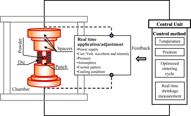
Principle of ECAS central control unit permitting real time monitoring and adjustment of all operating parameters (i.e. temperature, displacement and densification time) based on a feedback control system.
The ECAS process became highly reproducible with the installation of multiple peripheral units (table 5). Apparatuses included special purpose hardware and software for multi-parameter optimization by adjusting pulse duration, duty cycle (on-time/off-time), peak current, applied voltage, repetition frequency, waveform, heating and cooling rates, primary power supply and vacuum/atmosphere control.
In ultrafast ECAS, temperature measurements are more difficult than in fast ECAS because of the high heating rate and the localized heating between particles. Typically, ultrafast ECAS is controlled by monitoring the voltage or capacitor energy through their capacity and ultimately the number of discharges [72]. Recently, Bauer and Newman have developed [94] a more advanced system suitable for short time sintering (0.1–1 s) under 400–700 MPa in which the supplied energy is rapidly controlled by a feedback signal during sintering.
Heating methods
The heating method is of paramount importance in ECAS since it affects (a) the heating rate, (b) the temperature distribution and (c) the electric power consumption.
In fast ECAS, heating rates are on the order of 106 °C s−1. The temperature distribution is crucial either for fabricating fully homogeneous and dense compacts or for selectively sintering the compacts (i.e. FGMs).
Die-surrounded furnace and external preheating
The optimum combination of direct and indirect heating (figure 9(b)) ensures temperature uniformity across the compact. The superposition of direct and indirect heating is named the dual heating mode and was originally patented by Engle in 1940 [71]. The indirect heating was generated by a die-surrounded radiation furnace. The compact diameter could be increased to 7.5 cm, which is much larger than those reported in other patents (table 3). In 1978, Bakul et al [105] adopted a high-frequency, indirect current source to attain heating rates of up to 104 °C min−1. Their primary purpose was to prevent the graphitization of diamond and to ensure a uniform temperature distribution across a WC-6 %wt Co/diamond compact during sintering at 1800 °C with 2 to 3 s holding time.
Modern dual heating methods are particularly effective in ensuring uniform densification [106] in large samples (30 cm diameter).
Die preheating is included in modern automatic ECAS apparatuses [82] to minimize the thermal gradients, thereby ensuring high production rates. With this regard, Tokita [82] developed a die preheating stage (figure 12(a)). The die can be heated using an external heat generator or a high-frequency electromagnetic induction heater. In most equipment, the preheating stage is located along the transportation path of the sintering die, immediately downstream the automatic powder feeder.
Application of current from die side faces
In fast ECAS, microstructure inhomogeneities have been reported to result from high heating rates [98, 107, 108] and have been frequently attributed to excessive thermal gradients that develop in the compacts.
To reduce the sintering time without sacrificing compact homogeneity, Sunamoto [109] patented the system shown in figure 17. In his apparatus, the powder is uniaxially pressed between two ceramic punches while the current is alternately applied to a group of electrode pairs located around the die surface. An improvement was proposed by Ishida et al [110] who used nonconductive punches to achieve much larger pressures. An alternative method was proposed by Tokita and Miyake [111], so-called Super high-speed temperature rise sintering in which the currents are driven by the electrodes surrounding the die (figure 17) and the pressure is exerted by the upper and lower punches which also act as electrodes.
Figure 17.
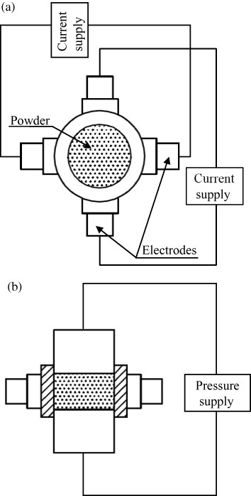
(a) Top and (b) front view of Sunamoto's heating system: current is discharged by two pairs of electrodes, which are brought into contact with the outer die surface while the powder is pressed by punches (adapted from [109]).
In 1993, Takahara [112] patented a distributed capacitor discharge heating source for ultrafast ECAS as shown in figure 18. The die consists of a number of alternating conductive and insulating rings. Each conductive ring is directly connected to a capacitor through an electric switch. The conductive powders are pressed between the punches. The switches are successively or simultaneously closed and the powder is uniformly sintered.
Figure 18.
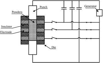
Sintering apparatus consisting of a die made of alternating conductive/nonconductive hollow cylinders; the conductive cylinders are connected to capacitors through electric switches (adapted from [112]).
Heating methods to minimize heat losses and energy consumption
In general, ECAS processes are energetically efficient since they can use two-thirds to four-fifths of the energy of conventional HP [28]. Both localized heating and the reduced sintering time significantly contribute to energy saving. Sunamoto [113] patented a method to further decrease the energy consumption. The apparatus in figure 19(a) includes thermal buffers mounted between the rams and punches which dramatically reduce the heat extracted by the cooling system. A variant of this method was proposed by Kikuchi et al [114] as shown in figure 19(b). The cross section area of the electrodes is progressively decreased to reduce the heat extracted by the cooling system and to concentrate the resistive heating in the powders.
Figure 19.
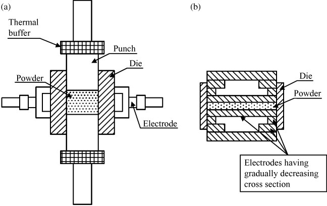
Methods to reduce electric energy consumption by minimizing heat conduction from the punches to the cooling system: (a) using thermal buffers [113] and (b) by the progressive reduction of punch cross section [114] (adapted from [113, 114], respectively).
Current path control
In conventional ECAS, the punch/die assembly (figure 4(b)), diverts the applied currents to the conductive die rather than across the powder. In a number of patents the difficulty of controlling the current path and leakage has been addressed. Current leakage between the die and punches is limited by interposing an adiabatic layer [115] or by using shaped punches [116] (see figure 20(a)), respectively. Moreover, both inventions promote the concentration of heat and reduce energy consumption.
Figure 20.
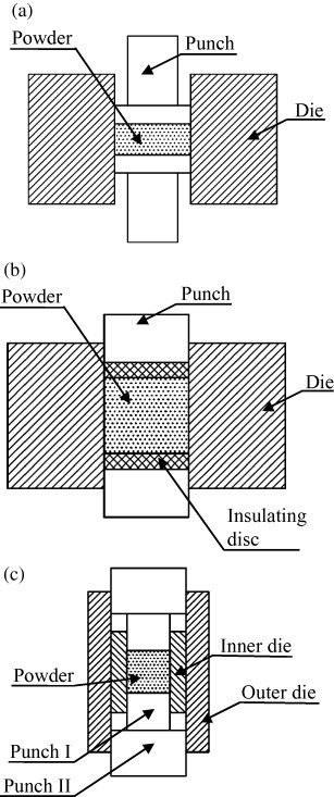
Methods of controlling current distribution across punch/die/compact assembly: (a) currents are forced to flow across powders, (b) two electrically insulating discs—interposed between the punches and sample inhibit current flow across the powder and (c) uniform current and temperature distributions across the punch/die/compact assembly are promoted by preventing overheating at the punch/spacer interface (adapted from [116, 117, 119], respectively).
On the other hand, in conventional punch/die assemblies (figure 4(b)) overheating occurs near the punch/spacer contact. Matsui et al in 1995 [117] and Kudo et al in 2001 [118] solved the overheating problem by the design of a new die design as shown in figure 20(c). Two coaxial dies help uniformly distribute the currents. With this system, the current density near the punch/spacer contact is appreciably lowered thus, making the overall temperature field more uniform.
Current and temperature fields in the powder are affected by electric and thermal conductivities. Fujita et al [119] inhibited the current flow toward the powder (figure 20(b)) by interposing a pair of electrically insulating discs between the punches and the powder. They succeeded in controlling the temperature distribution regardless of the powder conductivity. Conversely, Kamimura and Honma [120] developed a method for sintering nonconductive ceramic powders by coating them with conductive particles.
Figure 21 shows another method to control the current path. A number of electrode pairs are grouped together and each pair is controlled independently. Using this principle, in 1979 Inoue [121, 122] developed a method to uniformly sinter powder compacts. He independently controlled the current, pressure and position of each movable electrode pair (i.e. A, B and C, see figure 21(a)). The uniformity and compactness of sintering bodies is improved further by Mochizuki and Fujita [123]. The current path was arbitrarily changed during sintering to promote the uniform heating of the compact (figure 21(b)).
Figure 21.
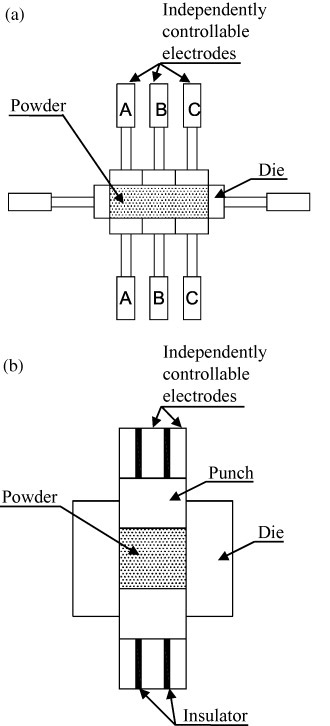
Schematic of patented methods for current path control using independently controllable electrodes (adapted from [122, 123], respectively).
Sintering in the presence of temperature gradient is a peculiar factor of ECAS which makes it particularly suitable for the fabrication of FGMs. A typical die for the production of FGMs is shown in figure 22. An increase in the cross section area of the die decreases the Joule heating [124]. Tokita et al in 2001 successfully sintered a zirconia/stainless steel FGM [125]. The sintering temperature along the axial direction is adapted to the local chemical composition by controlling the die wall thickness.
Figure 22.
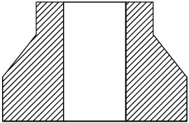
Cross section of the die used for the fabrication of functional graded materials (adapted from [124, 125].
Methods of pressure application and displacement control
Generally, if powders are heated while pressed, higher densification is achieved at the same temperature [2]. However, by increasing the applied pressure in ECAS, the contact resistance decreases both at interparticle contact points (in the case of conductive powders) and at the contact interfaces of apparatus members (i.e. punches, spacers, etc) consequently, at a given constant imposed current the resistive heating is reduced. To address this concern, Gillett and Dayton [69] reported that decreasing the pressure increased the final relative density of bronze compacts. By imposing a 1770 A current discharge and pressures of 5 and 10 MPa they achieved approximately 95 and 70% relative density, respectively, after 8–10 s. Analogously, Okazaki [39] showed, in the case of ultrafast ECAS (3–30 kV voltage and 10–500 μs discharge time), that a high loading pressure greatly reduced the specific resistance of the powder to a value comparable to the specific resistance of the power supply circuit, thereby preventing the full exploitation of the imposed current.
Application of uniaxial pressure
In early ECAS patents pressureless conditions were reported [4]. Currents were usually imposed on green bodies by two conducting members, acting only as electrodes. The advantage of applying a loading pressure was recognized later. In principle, a loading pressure ensures a firm contact between the electrodes and powder. In 1913, the loading pressure was applied by a heavy plate [62] (figure 7). In 1937, Kratky [70] designed a hammer impact loading system (figure 9(a)). Subsequently, in 1945, Ross [72] developed an automated sintering system simultaneously combining repeated impulsive loads and high intensity-current/low-voltage pulses.
Although the sliding electrode system was able to follow the dynamics of the compact during sintering shrinkage, it often led to irreproducible results and to poor-quality sintered products compared with those obtained by conventional sintering.
Inoue's patents [10, 32, 33, 73, 126] introduced the basic principle of discrete sparking at particle interfaces as an effective means of promoting local heating and thus interparticle bonding. Specifically, he discovered that pulsed currents combined with a pressure lower than 10 MPa promoted interparticle bridging by spark discharges in the first stage of sintering, while a higher pressure maximizes densification in the final stage of sintering. Conversely, high pressure was effective in the final stage of sintering since it promoted the plastic deformation of particles. Furthermore, in 1967 Inoue [32] claimed that the sonic or ultrasonic vibration of at least one electrode enhanced sparking phenomena.
Control of both the applied pressure and the position of movable electrodes in early apparatuses were very difficult, particularly in real time. In 1970, Inoue [127] solved this problem by patenting a programmable servo control system. This was capable of controlling the applied pressure and the position/velocity of at least one sliding electrode automatically during discharge sintering. Pressure and position were controlled according to one or more process parameters such as voltage, current and power. His patent [127] included the example of sintering Ni powder. Specifically, 2.2 g of powder was placed in a die (15 mm diameter) and discharged by the superimposition of both a direct current of 760 A (9 V) and a pulsed current of 600 A (2 kHz) for about 3 s. The loading pressure (hydraulic) was initially set to 0.5 MPa, then progressively raised to 20 MPa in 3 s. Three target relative densities, namely 70, 75 and 80%, were compared in terms of the specific energy consumption with and without the servo control system. Without the servo control system, 37.5, 42.5 and 46 kJ g−1 specific energies were consumed to attain the target densities. Incidentally, the free electrode could follow (upon its own weight) the powder shrinkage dynamics. By repeating the sintering process with the servo control system, the required specific energies decreased to 25, 29 and 32 kJ g−1, respectively. Surprisingly, it was found that dc power sources, although less effective than pulsed dc, could be used in spark sintering in combination with the servo control system.
Subsequently, Inoue [128] patented an improved version of the servo control system proposed in [127]. During sintering, a pulse generator was instantaneously switched off at prescribed times and the electric resistance of the compact was measured with a resistance detector. The inherent output was transmitted to a control device to determine the sintering progress by adapting the applied pressure.
In the 1990s, the first SPS machines, equipped with 10–100 t load cell and 2–20 kA dc pulse generator [80], started to be commercialized and their potential gradually became recognized worldwide. SPS machines proved effective for producing dense and uniform compacts. Punches and die were typically made of graphite with a bearing capacity of approximately 80–150 MPa.
However, weak graphitic dies posed severe limitations, particularly for high pressure sintering. In 2006, Anselmi-Tamburini et al [35, 129] reported a method for preparing dense functional oxides compacts with crystallite size in the range of 10–20 nm. Their hardware configuration is shown in figure 23(a). They used relatively short thermal cycles (<10 min) coupled with a progressive increase in pressure (up to 1 GPa) to promote a high degree of compaction and very limited grain growth. With the aim of developing a high pressure ECAS apparatus, Kamikawa and Kano [130] patented a new-concept die design (figure 23(b)) based on two coaxial hollow cylinders, the inner made of inexpensive (sacrificial) graphite and the outer made of high strength ceramic.
Figure 23.
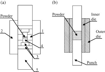
Schematic of high pressure sintering methods (up to 1 GPa). (a) The relevant parts are (1) internal smaller graphite die, (2) outer graphite die (3) two binderless tungsten carbide discs placed at the edge of each (4) SiC plunger. (b) The inner (sacrificial) graphite die is inserted inside a higher strength (permanent) die (adapted from [35, 130], respectively).
Uniaxial pressure in ultrafast ECAS
Typically, in ultrafast ECAS durable and relatively inexpensive materials are utilized. The punches and die are not severely heated and GPa pressure can be tolerated. This sintering process is also referred as ‘Cold die wall sintering’.
The method of pressure application depends on the specific process, as shown in table 4. Some apparatuses operate with a constant pressure, such as that patented by Cremer in 1944 [87]. Other systems, analogously to spot welding, apply an increasing load during sintering. All these processes take full advantage of the synergic effects of high pressure and high density current pulses. The method of pressure application exhibits a fast response through four basic mechanisms: (i) current flow across particles in contact, (ii) rapid heat generation at particle interfaces, (iii) the severe plastic deformation of heated particles and (iv) rapid densification.
Research and design in this field have mainly focused on optimizing the rapid follow-up system dynamics during powder shrinkage. Two interesting methods were proposed by Parker [88] and by Knoess and Schlemmer [93]. Parker utilized an existing patent on a so-called pressure transformer device [89] which was included in his ultrafast ECAS equipment. Alternatively, Knoess and Schlemmer [93] employed a spring element to constantly ensure that the originally imposed pressure remained applied to the powders. Mechanical or hydraulic presses were commonly used with equally good results [93].
Pseudo-isostatic pressure
A uniaxial pressure may lead to internal stress gradients in the compact resulting in nonuniform mass compaction [131]. Uniaxial pressure methods may fail to consolidate the mass at locations far from the punch surfaces; thus, the nonuniform passage of electric current through the powder can be expected. Conversely, pseudo-isostatic pressure may ensure a more uniform particle-to-particle contact pressure, thereby permitting homogeneous resistance heating. Note that the problems of particle-to-particle nonuniformity do not occur if external heating sources are employed. Thus, the application of pseudo-isostatic pressure prevents the development of internal stress gradients and generally results in an overall improvement in quality of the sintered compacts [131].
Inoue's patent issued in 1972 on ‘Electrical sintering under liquid pressure’ [131], was the first pseudo-isostatic ECAS in which the powder was isostatically compacted (see figure 24). Pressure was axially exerted on the powder by two electrodes and radially exerted onto a silicone-rubber meld by a liquid or gas medium through a flexible membrane. As an example, a WC-6%Co powder was rapidly sintered into a 5-mm-diameter disc (99.98% relative density) within 1.2 s using superimposed 1 kHz ac (30%) and dc (70%), while the chamber pressure was raised to 200 MPa.
Figure 24.
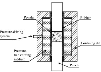
Cross-sectional view of electric sintering apparatus using a liquid pressure-transmitting medium (adapted from [131]).
On the basis of sintering methods that existed at that time, in 1994 Goldberger patented the ElectroconsolidationTM process [132] to produce metallic or ceramic products by rapid pressure-assisted densification. As shown in figure 25, the die contained a ‘pseudo-fluid’, consisting of floating electrically conductive (graphite) spheres 0.1–0.8 mm diameter surrounding a cold preform. Two graphite punches ensured a ‘pseudo-isostatic’ pressure over the preformed particulates through the pseudo-fluid. The spheres acted simultaneously as a pressure-transmitting medium and a heat source.
Figure 25.
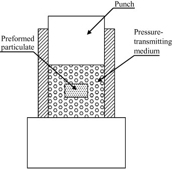
Partial view of longitudinal cross section of electroconsolidation® apparatus. Preform particulates are pressed between punches via solid pressure-transmitting media such as graphite spheres (adapted from [132]).
To enhance the homogeneity (i.e. quality), density and soundness of sintered bodies, particularly when particles have a strong tendency to generate a large amount of gas, in 1981 [133] and 1985 [134], Inoue developed a method based on the progressive application of a current and a triaxial pressure through a triaxial punch system, which also acts as a powder confining die. The method included three basic steps: (i) the approach of two punches along the x-direction, (ii) the resistive heating of the powder, (iii) the sequential compression and discharge along the y- and z-directions.
Shear stress and progressive compaction
In 1999 [13, 135], and subsequently in 2001 [136, 137], Yoo et al patented the so-called method of plasma pressure compactionTM (P2C) (see figure 26), which includes two steps. First, the powders are discharged by a pulsed current (1–2×10⁴ A) while shear stresses (5–50 MPa) are simultaneously applied by counter rotating punches to promote abrasive wear between particles, thereby facilitating the deagglomeration, compaction and fracture of surface oxide layers. Subsequently, the powders are subjected to a dc (1–2×10⁴ A) under a variable uniaxial pressure (1–2000 MPa) for a specified period of time. This reduces the sintering temperature compared with the case when no shear stress is applied [13].
Figure 26.
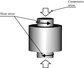
Schematic of stress application in plasma pressure compaction® (P2C). The electrodes may apply shear stress and/or uniaxial pressure (adapted from [13]).
Material and geometry of punch and die
It is well known that the material and geometry of the die and punch markedly affect the temperature and current distributions. Materials are selected depending on the (i) powder, (ii) sintering temperature, (iii) pressure, (iv) ECAS process (i.e. fast or ultrafast) and (v) punch and die lifetime.
In fast ECAS, graphite is typically selected as the die material since it is a good electric contact material, while exhibiting good electric conductivity, resistance to oxidation at high temperature, good thermal and mechanical stability at high temperatures and a high melting point [138]. The electrical resistivity of the punch and die controls the heating efficiency. On the basis of this principle, in 1978 Arvela [139] proposed a punch and die system made of a high resistive material—a graphite/concrete composite with a resistance of 0.03–100 Ω cm.
However, graphite has a relatively low bearing capacity. Nevertheless, most SPS elements are made of graphite with a maximum loading pressure of up to 80–150 MPa.
In place of graphite, in 1995 Fukuda et al [140] designed punches and spacers made of a composite material consisting of 5–40 wt% carbon and one or more carbide/boride of elements in the 4A, 5A and 6A groups which led to high compacting pressure, low electric power consumption and a longer service life. Analogously, applied pressure was increased using a high strength material such as WC, WC–Co or SiC. Steels were used in the case of low sintering- temperature material such as Al powder.
In the case of ultrafast ECAS, dies are typically made of electrically insulating materials such as glass, mica, alumina, thoria, magnesia, Bakelite or Teflon to prevent current leakage from the punches to the die. However, a conductive die with insulating coatings or flexible insulating sheets [115] can also be used.
One more crucial factor in ECAS is the contamination of the sintered body by the carbon die and punches. To overcome this problem, in 1972 Piper [141] patented a method based on tantalum or tungsten discs, which are inserted between the graphite punches and powder and act as a diffusion barrier. A more convenient alternative is the use of graphite foils. In industry, intermediate foils serve several purposes, they (i) prevent the reaction between the punch and the powder, (ii) minimize contact resistance between constitutive parts such as the punch, die and spacers, (iii) facilitate compact extraction with minimum damage to the punch or die surface and (iv) extend the life of the punch/die assembly. A consequence of the reduced contact resistance is the minimum thermal gradient along the punch/die radius, which is desirable for achieving homogeneous sintered products.
Regarding the punch and die geometry, a number of designs have contributed to the production of near-net-shape sintered products, as shown in table 2.
Magnetic field and texture orientation
Magnetic field sources have been combined with ECAS apparatuses to control the texture orientation, which is of special interest for the production of magnetic materials. In 1990, Hiroyoshi [142] and in 2003 Ozaki et al [143], independently patented a fast ECAS method sinter powders or compacts, in which a magnetic field is applied before [142] or during [143] sintering to promote a texture oriented along the pressing axis.
Sintering chamber atmosphere control unit
Most of ECAS patents employ specific sintering atmospheres, i.e. vacuum, inert gas, air, although the atmosphere may significantly affect the final properties of the sintered products. Sintering can be operated under an oxidizing, inert or reducing atmosphere and even in liquid media. In the latter case a dielectric is preferred to prevent sparking.
Concluding remarks
The present work was motivated by the widely recognized scientific and industrial importance of ECAS technologies. A subset of 119 patents (out of 642) that significantly contributed to the evolution of ECAS apparatuses and methods was reviewed. ECAS technology was found to have been established in 1906 by Bloxam, much earlier than claimed in previous reviews.
The selected patents traced the historical development of ECAS technology and the apparatuses and or methods used therein. According to the specific features of the individual patents, a classification of ECAS into basic ECAS and auxiliary devices/peripheral units is proposed. In the past century, the simultaneous development of basic ECAS apparatuses and peripheral units was fundamental in overcoming intrinsic technological limitations and in optimizing ECAS processes with respect to (a) product size, (b) microstructure homogeneity, particularly for large compacts, (c) process reproducibility and (d) processing parameters.
On the basis of the discharge time we classified the basic ECAS as fast and ultrafast ECAS. Most of ECAS patents found focused on fast ECAS.
Ultrafast ECAS developed independently of fast ECAS. It was pioneered by Taylor in 1933 and extended thereafter by Okazaki and Knoess. Ultrafast ECAS patents mainly differed in applied pressure, voltage and current density.
The industrialization and commercialization of fast ECAS evolved through three stages, an exploration stage (1900–1960), a development stage (1960–1990) and an exploitation stage (1990–2008). The exploration stage was mainly driven by the strong need of improved refractory products, cutting tools, abrasives and oil free bearings. Early machines were limited by electric power, mechanical pressure and process control.
The development stage was strongly influenced by Inoue's patents, which contributed to brighten up fast ECAS. He pioneered the pulsed electric current sintering (PECS) method and reconsidered the method of pressure application and the current waveforms. Inoue's patents were not put into wide use at that time owing perhaps to the high cost of equipment, lack of repeatability or low sintering efficiency. PECS inspired the development of plasma assisted sintering (PAS), spark plasma sintering (SPS) and plasma pressure compaction® (P2C).
The exploitation stage arrived with the worldwide availability of Japanese SPS apparatuses. Tokita contributed to the development of fully automated SPS apparatuses, which decreased production costs and increased productivity. The near-net-shape capability, versatility and the recognized technological and economical benefits of ECAS stimulated the industry sector.
The principles of early patents on ECAS are still employed in modern apparatuses. It is believed that their deeper understanding is useful for future ECAS development.
Acknowledgments
This work was supported by the World Premier International Research Center Initiative (WPI Initiative), program supported by MEXT, Japan. The authors are grateful to SPS Syntex Inc. (Japan) for providing SPS figures and for encouraging fruitful discussions.
References
- Orrú R, Licheri R, Locci A M, Cincotti A and Cao G. 2009. Mater. Sci. Eng. R 63 127 10.1016/j.mser.2008.09.003 [DOI] [Google Scholar]
- Munir Z A, Anselmi-Tamburini U. and Oyanagi M. J. Mater. Sci. 2006;41:763. doi: 10.1007/s10853-006-6555-2. [DOI] [Google Scholar]
- Duval D'Adrian A L. 1922. US Patent No. 1,430,724 [Google Scholar]
- Bloxam A G. 1906. GB Patent No. 27,002 [Google Scholar]
- Bloxam A G. 1906. GB Patent No. 9020 [Google Scholar]
- Taylor G F. 1932. GB Patent No. 385,629 [Google Scholar]
- Taylor G F. 1933. US Patent No. 1,896,854 [Google Scholar]
- Taylor G F. 1933. US Patent No. 1,896,853 [Google Scholar]
- Kim D K, Pak H R. and Okazaki K. Mater. Sci. Eng. 1988;104:191. doi: 10.1016/0025-5416(88)90421-1. [DOI] [Google Scholar]
- Inoue K. 1966. US Patent No. 3,241,956 [Google Scholar]
- Wada M. and Yamashita F. Intermag Conf. (Brighton, UK); 1990. p. p. 2601. [Google Scholar]
- Tokita M. 1993. J. Soc. Powder Technol. 30 790 (in Japanese) [Google Scholar]
- Yoo S H, Sethuram K M and Sudarshan T S. 1999. US Patent No. 5,989,487 [Google Scholar]
- Olevsky E A, Kandukuri S. and Froyen L. J. Appl. Phys. 2007;102:114913. doi: 10.1063/1.2822189. [DOI] [Google Scholar]
- McWilliams B, Zavaliangos A, Cho K C. and Dowding R J. JOM. 2006;58:67. doi: 10.1007/s11837-006-0218-2. [DOI] [Google Scholar]
- Zhang J, Zavaliangos A. and Groza J R. P/M Sci. Technol. Briefs. 2003;5:5. [Google Scholar]
- Shakery M, Al-Hassani S T S. and Davies T J. Powder Metall. Int. 1979;11:120. [Google Scholar]
- Clyens S, Al-Hassani S T S. and Johnson W. Int. J. Mech. Sci. 1976;18:37. doi: 10.1016/0020-7403(76)90073-4. [DOI] [Google Scholar]
- Alp T, Al-Hassani S T S. and Johnson W. Mech. Mater. Struct. Trans. ASME. 1985;107:186. [Google Scholar]
- Elkabir G, Rabenberg L, Persad C. and Marcus H L. Scr. Metall. 1986;20:1411. doi: 10.1016/0036-9748(86)90106-7. [DOI] [Google Scholar]
- Fais A. and and G. J. Mater. Proc. Technol. 2008;202:70. doi: 10.1016/j.jmatprotec.2007.09.012. [DOI] [Google Scholar]
- Saito S, Ishiyama T. and Sawaoka A. Bull. Tokyo Inst. Technol. 1974;12:137. [Google Scholar]
- Leroy L M. 1972. GB Patent No. 1,268,718 [Google Scholar]
- Yoshikawa N, Ishizuka E, Mashiko K, Chen Y. and Taniguchi S. ISIJ Int. 2007;47:523. doi: 10.2355/isijinternational.47.523. [DOI] [Google Scholar]
- Berghaus B and Burkhardt W. 1940. US Patent No. 5,405,574 [Google Scholar]
- Chelluri B and Barber J P. 1995. US Patent No. 5,405,574 [Google Scholar]
- Chelluri B and Barber J P. 1997. US Patent No. 5,611,139 [Google Scholar]
- Tokita M. Mater. Sci. Forum. 2003;423:39. doi: 10.4028/www.scientific.net/MSF.423-425.39. [DOI] [Google Scholar]
- Groza J R and Kodash V. 2005. US Patent No. 7,393,559 [Google Scholar]
- Fujii Y and Tokita M. 2002. JP Patent No. JP2002047504 [Google Scholar]
- Zhang L, Yang Z and Gong D. 2004. CN Patent No. CN1544187 [Google Scholar]
- Inoue K. 1967. US Patent No. 3,340,052 [Google Scholar]
- Inoue K. 1967. US Patent No. 3,317,705 [Google Scholar]
- Hiyama S, Sato T, Hiraide T and Miyake S. 1999. JP Patent No. JP11291173 [Google Scholar]
- Anselmi-Tamburini U, Munir Z A and Garay J E. 2006. World Intellectual Property Patent No. WO2006113354 [Google Scholar]
- Tokita M, Suzuki S and Nakagawa K. 2006. Euro. Patent No. EP1839782 [Google Scholar]
- Mizushima T, Makino A and Inoue A. 2000. US Patent No. 6,086,651 [Google Scholar]
- Yoshida S, Kenmotsu H, Mizushima T, Ikarashi K and Naito Y. 2003. US Patent No. 6,897,718 [Google Scholar]
- Okazaki K. 1990. US Patent No. 4,929,415 [Google Scholar]
- Watari F, Omori M and Hirai T. 2001. JP Patent No. JP2001259017 [Google Scholar]
- Hulbert D M, Kuntz J D and Mukherjee A K. 2007. US Patent Publ. No. 20070132154 [Google Scholar]
- Zhan G, Mukherjee A K, Kuntz J D and Wan J. 2005. World Intellectual Property Publ. No. WO2005003036 [Google Scholar]
- Shimada S and Takahashi J. 2000. JP Patent No. JP2000302545 [Google Scholar]
- Shimada S and Takahashi J. 2006. JP Patent No. JP2000302546 [Google Scholar]
- Moro H and Miyauchi Y. 1993. US Patent No. 5,227,235 [Google Scholar]
- Fujita K, Makino A and Inoue A. 2001. US Patent No. 6,172,589 [Google Scholar]
- Seth B B, Wagner G P and Swartzbeck G W. 2002. US Patent No. 6,384,365 [Google Scholar]
- Zhang M and Lu Y. 2006. Euro. Patent No. EP1820224 [Google Scholar]
- Konishi A and Fukuda K. 2001. US Patent No. 6,222,242 [Google Scholar]
- Xie G, Ohashi O, Yamaguchi N and Wang A. 2003. Met. Mater. Trans. A 34 2655 10.1007/s11661-003-0024-1 [DOI] [Google Scholar]
- Anderson K R, Groza J R, Fendorf M and Echer C J. 1999. Mater. Sci. Eng. A 270 278 10.1016/S0921-5093(99)00197-5 [DOI] [Google Scholar]
- Jones G, Groza J R, Yamazaki K. and Shoda K. Mater. Manuf. Process. 1994;9:1105. doi: 10.1080/10426919408934978. [DOI] [Google Scholar]
- Wada S. 1998. JP Patent No. JP5279711 [Google Scholar]
- Kaneuchi A and Morita H. 2004. JP Patent No. JP2004168632 [Google Scholar]
- Okano M and Izui H. 2007. World Intellectual Property Patent Publ. No. WO2007069623 [Google Scholar]
- Yamashita F and Wada M. 1993. JP Patent No. JP5198452 [Google Scholar]
- Ikeda H. 2005. JP Patent No. JP2005272254 [Google Scholar]
- Kamimura T and Tsujimura A. 1991. JP Patent No. JP3267552 [Google Scholar]
- Nakano T, Ide H and Nakamura H. 1989. JP Patent No. JP1228730 [Google Scholar]
- Kamitsuma Y. et al 1994. US Patent No. 5,346,667 [Google Scholar]
- Ward M. 1984. US Patent No. 4,456,578 [Google Scholar]
- Weintraub G and Rush H. 1913. US Patent No. 1,071,488 [Google Scholar]
- Davis N R. 1927. GB Patent No. 274,283 [Google Scholar]
- Sherwood C F. 1931. GB Patent No. 365,068 [Google Scholar]
- Sherwood C F. 1933. GB Patent No. 391,155 [Google Scholar]
- Hoyt S L. 1932. US Patent No. 1,843,768 [Google Scholar]
- Gilson E G. 1930. US Patent No. 1,756,857 [Google Scholar]
- British Thomson Houston Co., Ltd 1935. GB Patent No. 436,430 [Google Scholar]
- Gillett H W and Dayton R W. 1939. US Patent No. 2,149,596 [Google Scholar]
- Kratky A. 1937. US Patent No. 2,089,030 [Google Scholar]
- Engle E W. 1940. US Patent No. 2,195,297 [Google Scholar]
- Ross W F. 1945. US Patent No. 2,372,605 [Google Scholar]
- Inoue K. 1966. US Patent No. 3,250,892 [Google Scholar]
- De Groat G. Powder Metall. Parts Am. Mach. 1965;109:107. [Google Scholar]
- Boesel R W, Jacobson M I. and Yoshioka I S. J. Mater. Eng. 1969;70:32. [Google Scholar]
- Boesel R W. Metal Progress. 1971;99:74. [Google Scholar]
- Boesel R W. and Goetzel G C. Powder Metall. Int. 1971;3:38. [Google Scholar]
- Omori M. 8th Int. Conf. on Microwave High Frequency Heat (Bayreuth , Germany , Sept. 3–7).2001. [Google Scholar]
- Yamashita F and Wada M. 1993. JP Patent No. JP5198452 [Google Scholar]
- Inoue K. 1991. JP Patent No. JP3056604 [Google Scholar]
- Tokita M. 2001. JP Patent No. JP2001262202 [Google Scholar]
- Tokita M. 2002. US Patent No. 6,383,446 [Google Scholar]
- Tokita M and Nakagawa K. 2002. JP Patent No. JP2002206102 [Google Scholar]
- Tokita M, Nakagawa K and Ishida S. 2004. JP Patent No. JP2004244662 [Google Scholar]
- Tokita M. 2005. US Patent No. 6,881,048 [Google Scholar]
- Tokita M, Suzuki S and Nakagawa K. 2007. Euro. Patent No. EP1839782 [Google Scholar]
- Cremer G D. 1944. US Patent No. 2,355,954 [Google Scholar]
- Parker J C. 1968. US Patent No. 3,567,903 [Google Scholar]
- Vang A. 1962. US Patent No 3,059,094 [Google Scholar]
- Hetherington J S. 1969. US Patent No. 3,445,625 [Google Scholar]
- Okazaki K. 1992. US Patent No. 5,084,088 [Google Scholar]
- Okazaki K, De Angelis R J and Hamrin C E. 1990. US Patent No. 4,975,412 [Google Scholar]
- Knoess W and Schlemmer M. 1996. US Patent No. 5,529,746 [Google Scholar]
- Bauer D P and Newman D C. 2008. US Patent No. 7,361,301 [Google Scholar]
- Michalski A, Jaroszewicz J. and Rosinski M. Int. J. Self Propagat. High Temp. Synth. 2003;12:237. [Google Scholar]
- Michalski A, Jaroszewicz J, Rosinski M. and Siemiaszko D. Intermetallics. 2006;14:603. doi: 10.1016/j.intermet.2005.10.003. [DOI] [Google Scholar]
- Shimizu M. 1978. JP Patent No. JP53109807 [Google Scholar]
- Vanmeensel K, Laptev A, Hennicke J, Vleugels J. and Van der Biest O. Acta Mater. 2005;53:4379. doi: 10.1016/j.actamat.2005.05.042. [DOI] [Google Scholar]
- Mori K. 2000. JP Patent No. JP2000073103 [Google Scholar]
- Augsburg-Nurnberg A G Maschf. 1953. GB Patent No. 697,614 [Google Scholar]
- Inoue K. 1996. JP Patent No. JP8041507 [Google Scholar]
- Inoue K. 1982. GB Patent No. 2,084,350 [Google Scholar]
- Inoue K. 1991. JP Patent No. JP3236402 [Google Scholar]
- Inoue K. 1991. JP Patent No. JP3236403 [Google Scholar]
- Bakul V, Bilyk I I, Bronshtein D K, Vovchanovsky I F and Tsypin N V. 1978. US Patent No. 4,097,274 [Google Scholar]
- Kessel H U. and and H. J. Interceram. 2007;56:164. [Google Scholar]
- Maizza G, Grasso S, Sakka Y, Noda T. and Ohashi O. Sci. Technol. Adv. Mater. 2007;8:644. doi: 10.1016/j.stam.2007.09.002. [DOI] [PMC free article] [PubMed] [Google Scholar]
- Maizza G, Grasso S. and Sakka Y. J. Mater. Sci. 2009;44:1219. doi: 10.1007/s10853-008-3179-8. [DOI] [PMC free article] [PubMed] [Google Scholar]
- Sunamoto K. 2003. US Patent No. 6,610,246 [Google Scholar]
- Ishida H, Morioka S and Araki T. 2004. JP Patent No. JP2004068089 [Google Scholar]
- Tokita M and Miyake M. 2002. JP Patent No. JP2002088404 [Google Scholar]
- Takahara K. 1993. JP Patent No. JP5117707 [Google Scholar]
- Sunamoto K. 2008. JP Patent No. JP2008095196 [Google Scholar]
- Kikuchi K, Kikuchi H, Kikuchi M, Kikuchi T and Kikuchi R. 2002. JP Patent No. JP2002363612 [Google Scholar]
- Majkic G and Salama K. 2008. World Intellectual Property Publ. No. WO2008085947 [Google Scholar]
- Mochizuki T, Fujita K and Mori K. 1999. JP Patent No. JP11343505 [Google Scholar]
- Matsui S, Tokita M, Akashi T and Tani M. 1995. JP Patent No. JP7216409 [Google Scholar]
- Kudo H, Ando H and Taguchi A. 2001. JP Patent No. JP2001348277 [Google Scholar]
- Fujita K, Mochizuki T and Mori K. 2000. JP Patent No. JP2000063907 [Google Scholar]
- Kamimura T and Honma K. 1992. JP Patent No. JP4037655 [Google Scholar]
- Inoue K. 1979. JP Patent No. JP54024208 [Google Scholar]
- Inoue K. 1979. JP Patent No. JP54024207 [Google Scholar]
- Mochizuki T and Fujita K. 1998. JP Patent No. JP10204505 [Google Scholar]
- Akashi T, Tokita M, Kawahara M and Matsui S. 1994. JP Patent No. JP6287076 [Google Scholar]
- Tokita M, Kawahara M, Nakayama Y and Sonoda M. 2001. JP Patent No. JP2001220247 [Google Scholar]
- Inoue K. 1968. US Patent No. 3,364,333 [Google Scholar]
- Inoue K. 1970. US Patent No. 3,508,029 [Google Scholar]
- Inoue K. 1991. JP Patent No. JP3193803 [Google Scholar]
- Anselmi-Tamburini U, Munir Z A. and Garay J E. Scr. Mater. 2006;54:823. doi: 10.1016/j.scriptamat.2005.11.015. [DOI] [Google Scholar]
- Kamikawa M and Kano Y. 2001. JP Patent No. JP2001226703 [Google Scholar]
- Inoue K. 1972. US Patent No. 3,656,946 [Google Scholar]
- Goldberger W M. 1994. US Patent No. 5,348,694 [Google Scholar]
- Inoue K. 1981. US Patent No. 4,273,581 [Google Scholar]
- Inoue K. 1985. US Patent No. 4,536,366 [Google Scholar]
- Yoo S H, Sethuram K M and Sudarshan T S. 1999. US Patent No. 6,001,304 [Google Scholar]
- Yoo S H, Sethuram K M and Sudarshan T S. 2001. US Patent No. 6,187,087 [Google Scholar]
- Yoo S H, Sethuram K M and Sudarshan T S. 2001. US Patent No. 6,183,690 [Google Scholar]
- Savvatimskiy A I. Carbon. 2005;43:1115. doi: 10.1016/j.carbon.2004.12.027. [DOI] [Google Scholar]
- Arvela A. 1978. US Patent No. 4,102,679 [Google Scholar]
- Fukuda M, Ono T, Shinpo A, Sato Y, Endo H and Ueki M. 1995. JP Patent No. JP7247172 [Google Scholar]
- Piper T E. 1972. US Patent No. 3,665,151 [Google Scholar]
- Hiroyoshi H. 1990. JP Patent No. JP2309607 [Google Scholar]
- Ozaki K, Kobayashi K, Kikuchi K and Kikuchi H. 2003. JP Patent No. JP2003328008 [Google Scholar]
- Willey F H. 1937. US Patent No. 2,074,038 [Google Scholar]
- Willey F H. 1938. US Patent No. 2,133,495 [Google Scholar]


