

Multiphase and cross-scale manipulations of objects with diverse properties for 3D hydrogel construction.
Keywords: Hydrogel, electrowetting, dielectrophoresis, microfluidics
Abstract
Formation of multifunctional, heterogeneous, and encoded hydrogel building blocks, or microgels, by crosslinking and assembly of microgels are two essential steps in establishing hierarchical, complicated, and three-dimensional (3D) hydrogel architectures that recapitulate natural and biological structures or originate new materials by design. However, for the variety of the hydrogel materials crosslinked differently and for the varied scales of microgels and architectures, the formation and assembly processes are usually performed separately, which increases the manufacturing complexity of designed hydrogel materials. We show the construction of hydrogel architectures through programmable formation and assembly on an electromicrofluidic platform, adopting two reciprocal electric manipulations (electrowetting and dielectrophoresis) to manipulate varied objects (i) in multiple phases, including prepolymer liquid droplets and crosslinked microgels, (ii) on a wide range of scales from micrometer functional particles or cells to millimeter-assembled hydrogel architectures, and (iii) with diverse properties, such as conductive and dielectric droplets that are photocrosslinkable, chemically crosslinkable, or thermally crosslinkable. Prepolymer droplets, particles, and dissolved molecules are electrically addressable to adjust the properties of the microgel building blocks in liquid phase that subsequently undergo crosslinking and assembly in a flexible sequence to accomplish heterogeneous and seamless hydrogel architectures. We expect the electromicrofluidic platform to become a general technique to obtain 3D complex architectures.
INTRODUCTION
Assembling heterogeneous three-dimensional (3D) hydrogel architectures from crosslinked building blocks (microgels) that hold reconfigurable embedded objects or molecules is in great demand in various applications, including in the construction of artificial tissues (1) that recapitulate physiological functions by imitating biological structures and in the production of novel metamaterials (2) with properties atypical or nonexistent in nature. Diverse approaches to building block formation have been demonstrated, including batch emulsion polymerization (3), micromolding (4–7), photolithography (8, 9), and microfluidic-assisted fabrication (10), using multiphase emulsion microfluidics (11) or single-phase flow lithography (12–17). For most of the approaches, the shapes and materials of the building blocks are limited by the preparation methods; for example, emulsions basically produce spherical microcomponents (3, 11), whereas lithography generates only photocrosslinkable materials (8, 9, 12–17). Micromolding (4–7) gives flexibility in shapes and materials but lacks programmability in situ that, for example, encodes building blocks in flow lithography (12–17) by adjusting the laminar flows and light patterns. Nevertheless, flow lithography wastes excess solutions and requires a sophisticated optical apparatus to generate the light patterns. Finally, to provide delicate functionalities, the building blocks undergo manual assembly (4), self-assembly (5, 6, 8), or robotic assembly (7, 9). In general, self-assembly relies on the surface property and geometry of the building blocks and is difficult to realize heterogeneous architectures; manual assembly with micromanipulators is labor-intensive; robotic assembly requires precise motion of supplementary microrobots driven optically (7) or magnetically (9).
Here, we prepare microgels and assemble hydrogel architectures on an electromicrofluidic platform following predesigned programs without constraint of shape, material, and programmability; our process does not require excess prepolymer solutions, sophisticated optical apparatuses, or moving microrobots. Electrowetting (18, 19) and dielectrophoresis (20–22) are adopted on the platform for their reciprocal capabilities of driving objects in multiphases, on cross-scales (20), and of varied properties (21), as depicted in the Supplementary Materials and fig. S1 (A to C). In general, electrowetting reduces the contact angle of conductive liquids and attracts the droplets onto energized electrodes with appropriate surface coatings, whereas dielectrophoresis actuates dielectric droplets with higher permittivity toward high electric field regions. In addition, dielectrophoresis drives the cells, particles, or crosslinked microgels in liquid with nonuniform electric fields. Programmable droplets, consisting of various crosslinkable solutions, dispersed particles, and soluble molecules, are aliquoted, mixed, transported, and positioned. When needed, the microgels can be further encoded spectrally with adjustable colors, graphically with reorganized embedded particles, and geometrically with shapes. Post- and precrosslinking assemblies of the prepolymer droplets and the microgels, respectively, are developed to accomplish heterogeneous architectures on the platform.
RESULTS
Microgel formation
The conceptual electromicrofluidic platform is shown in Fig. 1A. Reservoirs on the sides accommodate crosslinkable elementary materials, which have diverse properties indicated by their colors: white (W), red (R), green (G), and blue (B), of which W and R additionally contain particles. On the electrode array, arbitrary combinations of the elementary materials are achievable with droplet aliquoting and mixing. For example, the upper right microgel (B+R+W) consists of three elementary materials and randomly dispersed particles, whereas the lower middle one contains the R+W mixture and reorganized particles. Programmable droplet manipulations and assemblies on the electromicrofluidic platform are facilitated by electrowetting and dielectrophoresis between plates holding appropriate electrodes and dielectric and hydrophobic layers, as shown in Fig. 1A. Electrowetting alters the contact angle of a conductive liquid on a solid surface by application of a voltage. As shown in the curves and insets of Fig. 1B, the variation of contact angle with electrowetting was obvious for conductive water and for the mixtures of water and poly(ethylene glycol) diacrylate (PEGDA; Mn of 575 Da) but negligible for dielectric pristine PEGDA (conductivity, 0.1 μS/cm) sessile drops (volume, 1.5 μl). Thus, we applied dielectrophoresis that efficiently drives dielectric droplets of higher permittivity into a region of large electric field and of lower permittivity (21, 22), as shown in Fig. 1C, to actuate PEGDA droplets (volume, 0.1 μl) between the two parallel plates (spacing, 100 μm) at a tunable velocity controlled by the electric signals switched among the driving electrodes (1 mm × 1 mm).
Fig. 1. Programmable electromicrofluidic platform for microgel formation and architecture assembly.
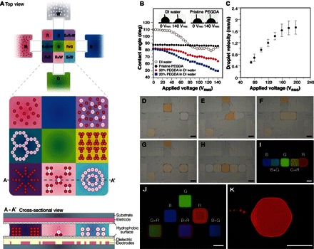
(A) Top and cross-sectional views of a conceptual electromicrofluidic platform that assembles an architecture consisting of 3 × 3 microgels prepared from four crosslinkable elementary materials (W, R, G, and B) through manipulations of suspended particles, liquid droplets, and crosslinked microgels by electrowetting and dielectrophoresis between parallel plates with appropriate electrodes and dielectric and hydrophobic layers. (B) Change of contact angle by electrowetting on sessile drops of water, PEGDA, and their mixtures with varied concentrations. DI, deionized; deg, degrees. (C) Moving velocity of a PEGDA droplet driven by dielectrophoresis on the electromicrofluidic platform. (D to H) Producing microgels by aliquoting, merging, mixing, splitting, and transporting, PEGDA droplets with rhodamine 6G (R6G) (R), fluorescein (G), and coumarin 450 (C-450) (B) dyes. (I) Crosslinking of single (G) and Janus binary (B/B+G and G+R/R) microgels after light exposure. (J) Microgels with configurable encoding colors by droplet manipulations (movie S1). (K) Hexagonal microgel. Scale bars, 1 mm.
With added photoinitiator, photocrosslinkable PEGDA microgels (Fig. 1I) were prepared by droplet aliquoting (Fig. 1D), merging (Fig. 1E), mixing (Fig. 1F), splitting (Fig. 1G), transporting, and positioning (Fig. 1H) from the three elementary PEGDA reservoirs with fluorescent dyes: R (R6G, right), G (fluorescein, upper), and B (C-450, left). A G+R droplet with G and R in equal proportion was obtained by merging two droplets, as shown in Fig. 1 (D to G). Various G/R ratios are readily obtainable by mixing droplets of appropriate numbers, which, in this case, adjusts the encoding color and, in other cases, modifies the chemical concentrations or physical properties of the microgels before crosslinking. After light exposure, single (G) and Janus binary (B/B+G and G+R/R) microgels, as shown in the fluorescence microscopy image of Fig. 1I, were crosslinked. The technique of contacting single microgels to make binary microgels is applicable to assemble a larger architecture. Single microgels with various encoding colors (Fig. 1J) were prepared with reconfigurable droplet handling procedures (movie S1). With varied electrode designs, microgels in desired shapes, for example, the hexagon in Fig. 1K, are possible. The electromicrofluidic platform is capable of manipulating droplets with large viscosity [1000 cSt (21)] and small volume [5 pl (23)].
Architecture assembly
Post- and precrosslinking assemblies in solid and liquid phases, respectively, are developed on the electromicrofluidic platform. As shown in Fig. 2 (A to C), postcrosslinking (crosslinked) PEGDA microgels (1 mm × 1 mm × 100 μm), similar to those shown in Fig. 1J, were harvested and driven in DI water between parallel plates (spacing, 300 μm) with dielectrophoresis on the electromicrofluidic platform. For an adequate gap height, stacking and layering of the microgels for 3D assembly were achieved (movie S2). Other than postcrosslinking assembly, precrosslinking assembly is shown in Fig. 2 (D and E) and movie S3; nine PEGDA prepolymer droplets were aliquoted from the reservoirs holding R, G, and B elementary materials and transported and assembled in the liquid phase. After light exposure, a seamless heterogeneous architecture (3 mm × 3 mm × 100 μm) was obtained (Fig. 2F) and accessible with tweezers (Fig. 2G).
Fig. 2. Multiphase post- and precrosslinking assemblies of architecture on the electromicrofluidic platform.
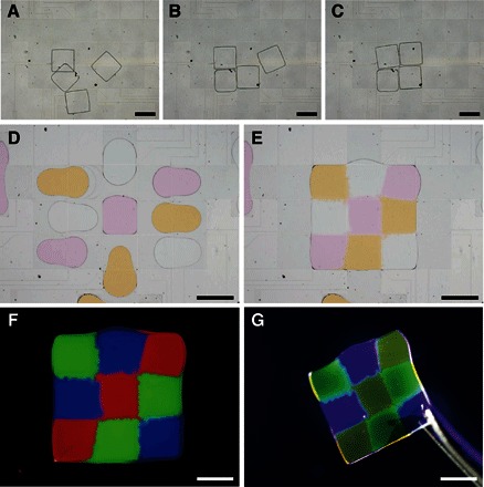
(A to C) Postcrosslinking assembly of crosslinked PEGDA microgels driven in water (movie S2). (D and E) Precrosslinking assembly of nine PEGDA prepolymer droplets with varied dyes to form a heterogeneous architecture (3 mm × 3 mm × 100 μm) after crosslinking on light exposure (movie S3). (F) Fluorescence microscopy image of the crosslinked heterogeneous architecture. (G) Architecture accessible with tweezers. Scale bars, 1 mm.
Heterogeneous architecture
The microgel formation and architecture assembly on the electromicrofluidic platform are applicable to other prepolymer solutions that are crosslinked differently. In addition, functional particles, which serve as microsensors, biological assays (11), and local chemical releasers (24), can be incorporated in the elementary materials to construct sophisticated architectures. As shown in Fig. 3A, photocrosslinkable PEGDA with green particles, thermally crosslinkable Matrigel with blue dye, and chemically crosslinkable polyacrylamide with red particles were manipulated and crosslinked on the electromicrofluidic platform.
Fig. 3. Multiphase and cross-scale assembly of architectures with microgels consisting of varied prepolymer solutions, dyes, and particles.
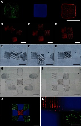
(A) Microgels crosslinked by different manners on a single electromicrofluidic platform. Left: PEGDA with green particles by photocrosslinking; middle: Matrigel with blue dye by thermal crosslinking; right: polyacrylamide with red particles by chemical crosslinking. (B to G) Postcrosslinking PEGDA microgels, containing random or reorganized encoding particles, assembled (B to D) and stacked (E to G) in liquid PEGDA solution (movie S4). (H and I) Precrosslinking assembly of nine PEGDA droplets with dye or addressable particles to form a PEGDA architecture (3 mm × 3 mm × 100 μm) after crosslinking on light exposure (movie S5). (J and K) Fluorescence microscopy images of the crosslinked and seamless heterogeneous architecture. Scale bars, 1 mm (A to J); 200 μm (K).
As shown in Fig. 3 (B to G) and movie S4, the crosslinked PEGDA microgels (height, 100 μm), which contain encoding particles reorganized by dielectrophoresis on patterned electrodes (fig. S1C) with nonuniform electric fields (fig. S1D), were harvested and assembled (Fig. 3, B to D) or stacked (Fig. 3, E to G) in another crosslinkable PEGDA prepolymer solution (height, 300 μm). A second exposure would secure the microgels and define the final architecture. Alternatively, precrosslinking assembly was performed, as shown in Fig. 3 (H to K). Nine precrosslinked droplets were aliquoted from the three elementary PEGDA materials with particles or dye (movie S5) and assembled on patterned electrodes that generated nonuniform electric fields to reorganize encoding particles with dielectrophoresis. Diffusion of the blue dye across the particles at the interface is visible in the magnified fluorescence microscopy images of Fig. 3K, which can be investigated to deliver adjustable chemical gradients before crosslinking. The seamless architectures were observed and confirmed with a confocal microscope and a scanning electron microscope (SEM), as shown in fig. S2.
Microgel and architecture for cells
2D and 3D cell patterns were achieved on the assembled architecture surface and within the crosslinked microgels, respectively. Heterogeneous architectures with distinct regional cell adhesion properties were produced from photocrosslinkable prepolymer solutions of PEGDA and gelatin methacryloyl (GelMA) (25, 26) hydrogel. The PEGDA-containing particles were aliquoted, encoded, and crosslinked; 8% (w/v) GelMA subsequently filled the space between PEGDA microgels. After the second exposure, the architecture was washed three times with a buffer and placed in a 24-well plate for cell seeding and culture. After 48 hours in culture on the heterogeneous architecture with PEGDA and GelMA, the tested NIH/3T3 fibroblasts (Fig. 4, A and B) were stained with Alexa Fluor 488 phalloidin/4′,6-diamidino-2-phenylindole (DAPI) staining for F-actin/nuclei, whereas the primary neonatal mouse cardiomyocytes (Fig. 4, C and D) were distinguished from cardiac fibroblasts by immunostaining of cardiac troponin I (cTnI), a cardiac regulatory protein related to the contractile behavior of the heart tissue. Both the fibroblasts and cardiomyocytes adhered mainly on the GelMA area, on which the average cardiomyocyte ratio over the entire cells, as shown in Fig. 4E, was above 50% and 1.8 times as great as that (that is, 27.8%) on a 24-well plate (Nunc Cell-Culture Treated Multidishes) surface of the control group at 48 hours in culture. As shown in Fig. 4F and movie S6, cardiomyocytes on GelMA at 24 hours in culture formed cell clusters that contracted individually and randomly at a rate of 73 to 91 beats/min (1.2 to 1.5 Hz); at 48 hours in culture, proliferated cardiac fibroblasts occupied the area between the cardiomyocyte clusters that were found synchronously contracted at a rate of 155 to 172 beats/min (2.6 to 2.9 Hz). The cardiac fibroblasts that tightly interconnect with neighboring cardiomyocyte clusters behaved as efficient mechanoelectrical transducers, where they varied their membrane potentials by stretching activated ion channels (27) in accordance with the surrounding mechanical stimuli (28) and thus synchronized the contractions. 2D NIH/3T3 fibroblast culture was further studied on a more complex hydrogel architecture, challenging other techniques with two exposures, composed of three elementary materials: two distinct PEGDA microgels with fluorescent red or green particles and the filling GelMA at varied concentrations (5, 8, and 10% w/v) and resultant stiffness (2.8, 6.6, and 20.2 kPa, respectively; fig. S3). Preliminary results after 48 hours in culture include slightly higher cell density on 8% GelMA and tendency of increased polarization and aspect ratio (29) of the fibroblasts on stiffer GelMA.
Fig. 4. 2D and 3D cell culture on architectures and within microgels with cross-scale cell patterns configured by surface properties and inner electric fields.
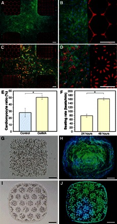
(A and B) NIH/3T3 fibroblasts, stained with Alexa Fluor 488 phalloidin (F-actin, green) and DAPI (nuclei, blue) at 48 hours in culture, growing on GelMA (8%) but not on PEGDA of the heterogeneous architecture. (C and D) Neonatal mouse cardiomyocytes patterned with GelMA/PEGDA surfaces and stained with Alexa Fluor 488 phalloidin, DAPI, and Cy3 (cTnI) at 48 hours in culture. (E) Cardiomyocyte ratio over the entire cells at 48 hours in culture on a 24-well plate as control and on GelMA of the architecture. (F) Beating rate of the cardiomyocytes at 24 and 48 hours in culture on GelMA of the architecture (movie S6). (G) GelMA (5%) microgel crosslinked with encapsulated random NIH/3T3 fibroblasts. (H) GelMA/cell microgel in (G) stained with Alexa Fluor 488 phalloidin and DAPI on day 5 in culture. (I) GelMA microgel crosslinked with encapsulated and reorganized NIH/3T3 fibroblasts (movie S7). (J) GelMA/cell microgels in (I) stained on day 3 in culture. *P < 0.01. Scale bars, 200 μm.
3D cell culture with random or reorganized NIH/3T3 fibroblasts (2 × 10⁷ cells/ml) in 5% (w/v) GelMA microgels was investigated. GelMA microgels with random cells were aliquoted, crosslinked (Fig. 4G), cultivated for 5 days, and immunostained (Fig. 4H). Cells reorganized with dielectrophoresis in 3D arrangements (confocal microscopy image in fig. S1E) emerged with excellent viability (more than 90% as shown in fig. S1, F and G), proliferation, and growth ability in GelMA microgels manipulated and crosslinked on the electromicrofluidic platform. Another method to aliquot droplets using electrowetting and hydrophilic surface patterns was reported for thermally crosslinkable hydrogels (30). With active electrodes, our aliquoted prepolymer droplets are ready for the ensuing processes. For example, the cells were reorganized to form cell patterns (shown as hexagons in Fig. 4I and movie S7) before GelMA crosslinking. Cell proliferation, pseudopodia extension (fig. S1H), and formation of 3D clusters were observed after 3 days in culture (Fig. 4J). MTT [3-(4,5-dimethylthiazol-2-yl)-2,5-diphenyltetrazolium bromide] assay was adopted to evaluate the viability of NIH/3T3 fibroblasts in GelMA microgels at days 0, 1, and 3 in culture; it confirmed the cell proliferation with time and showed no correlation between cell viability and dielectrophoresis manipulations (fig. S1I). The electromicrofluidic platform could also provide automatic medium exchanges for a cell culture on-chip, as previously reported (30). The reorganized cell patterns modulate cues in cellular microenvironments, facilitate cell-cell interactions in the cluster, and regulate cellular biological functions (31). In the application of biology and medicine, an architecture made of 3D hydrogels, which comprise drugs, growth factors, functional particles, and cells, provides a highly programmable in vivo–like microenvironment for cell behavior studies. The electromicrofluidic platform, which can manipulate objects in multiphases, on cross-scales, and of wide properties, thus accomplishes reconfigurable microgel formation and architecture assembly that would become an alternative and key technology to additive manufacturing and 3D bioprinting (32).
DISCUSSION
The electromicrofluidic platform provides versatile electric manipulations to prepare microgels with reorganized particle or cell patterns and to assemble heterogeneous hydrogel architectures. However, the patterns of the particles or cells and the geometry of the assembled architecture rely on the predesigned electrode patterns (fig. S1C). Improving the flexibility, driving particles, cells, and microgels on a large electrode array with fine electrodes (33) is possible. In addition, 3D assembly of microgels by stacking is dependent on the electric field strength between the parallel plates. Multilayer microgel stacking requires a higher applied voltage to compensate for the increase of height between plates.
In summary, we investigate and integrate two major electrical manipulations (electrowetting and dielectrophoresis) between two parallel plates of the electromicrofluidic platform. We overcome the manipulation barriers between phases, scales, and properties of the objects, which is challenging in other techniques. For the first time, various electrical manipulations were demonstrated on microgel formation and architecture assembly on a single platform at the same time. Liquid prepolymer droplets (0.1 μl) of dielectric PEGDA and conductive GelMA, Matrigel, and polyacrylamide were aliquoted, mixed, transported, and crosslinked as the microgels through photocrosslinking, thermal crosslinking, and chemical crosslinking. Solid objects on cross-scales, including micrometer particles and cells and millimeter crosslinked microgels, were reorganized and assembled. The implementation of the electromicrofluidic platform involved material science, physics, engineering, and microfluidics. The results of the heterogeneous architecture composed of microgels with tunable properties and embedded particles are applicable to material science, tissue engineering, biology, and additive manufacturing. 2D and 3D cell patterning and culture were conducted on the basis of the manipulation of biomaterial prepolymer droplets, cells, and microgels. The post- and precrosslinking assemblies—applicable to droplets of small volume (5 pl) or large viscosity (1000 cSt) and to objects in multiphases, on cross-scales, and of distinct properties—facilitate alternative and programmable 3D (bio)printing.
MATERIALS AND METHODS
Microgel materials
Photoinitiator 2-hydroxy-1-[4-(hydroxyethoxy)phenyl]-2-methyl-l-propanone (Irgacure 2959, CIBA Chemicals) was supplemented to prepare photocrosslinkable PEGDA and GelMA. PEGDA with Mn of 575 Da, viscosity of 57 cP, and density of 1.12 g/ml at 25°C was from Sigma-Aldrich. The PEGDA that contained photoinitiator (1% w/v) was crosslinked by exposure (100 mW/cm2) for 5 s to ultraviolet light (OmniCure S2000, Lumen Dynamics).
GelMA was synthesized from gelatin (type A, 300 bloom from porcine skin; Sigma-Aldrich) and methacrylic anhydride (Sigma-Aldrich) following the reported protocol (25). Briefly, gelatin powder (5 g) was fully dissolved in Dulbecco’s phosphate-buffered saline (DPBS; 50 ml; Gibco) and mixed with a magnetic rotator on a hot plate at 50°C, and then methacrylic anhydride (4 ml) was added dropwise and reacted at 50°C for 3 hours. After reaction for 3 hours, DPBS (200 ml) was added to dilute the GelMA solution. The final solution was then dialyzed within 12- to 14-kDa cutoff dialysis tubing (Spectra/Por molecular porous membrane tubing; molecular weight cutoff, 12 to 14 kDa) in distilled water for 1 week at 50°C and subsequently lyophilized for 1 week to obtain a GelMA porous foam. GelMA prepolymer solution was prepared by dissolving the lyophilized GelMA foam and photoinitiator in DPBS at an appropriate concentration at 80°C until it was fully dissolved. GelMA hydrogels with photoinitiator (0.5% w/v) were crosslinked by exposure (70 mW/cm2, 8 s) to ultraviolet light.
A thermally crosslinkable Matrigel (BD Biosciences) solution contained 10% (v/v) Matrigel and 90% (v/v) DPBS. Chemically crosslinkable polyacrylamide prepolymer solution consisted of a mixture of 40% acrylamide and 2% bis-acrylamide (N,N′-methylenebisacrylamide) at a volume ratio of 29:1, 1% (v/v) TEMED (N,N,N′,N′-tetramethylethylenediamine), and 0.01% (w/v) APS (ammonium persulfate), all from Sigma-Aldrich.
Fluorescent dyes at suitable concentrations—red R6G (0.1 mM; Sigma-Aldrich), green fluorescein (1 mM; Fluka), and blue C-450 (5 mM; Exciton)—were added to crosslinkable prepolymer solutions. Fluorescent green particles (diameter, 5 μm; excitation/emission, 468/508 nm) were from Thermo Scientific (Firefli fluorescent green polystyrene particles, G0500). Fluorescent red particles (diameter, 7.32 μm; excitation/emission, 540/600 nm) were from Bangs Laboratories (fluorescent suncoast yellow polystyrene divinylbenzene particles, FS06F/11234). The particles were dispersed in prepolymer solutions (concentration, 2% w/v).
Cell isolation, culture, and staining
All cells were cultivated in T75 flasks and kept at 37°C in a CO2 (5%) and air (95%) incubator. NIH/3T3 fibroblasts were maintained in Dulbecco’s modified Eagle’s medium (DMEM; HyClone) with 10% (v/v) fetal bovine serum (FBS; HyClone) and penicillin/streptomycin (Gibco; 100 U/ml). Cells grown to preconfluency were subcultivated every 2 to 3 days by trypsinization with 0.05% (w/v) trypsin-EDTA (Gibco).
Primary neonatal mouse cardiomyocytes were obtained from 0- to 2-day-old imprinting control region (ICR) mouse neonatal pups. The hearts of ICR mouse neonatal pups were excised and placed in cold Hanks’ balanced salt solution (HBSS; Gibco). After the atria and blood vessels were removed with small scissors and forceps, the remaining ventricles were transferred, quartered, and washed in a new plate containing fresh HBSS buffer. The heart tissue fragments were then incubated in a solution (0.05% w/v) of trypsin in HBSS buffer at 4°C for 3 to 6 hours on a shaker to digest the tissues. Before the next digestion step, the cardiac growth medium (DMEM) supplemented with FBS (10% v/v), penicillin/streptomycin (100 U/ml), l-glutamine (1 mM; Gibco), Hepes (5 mM; Sigma-Aldrich), vitamin B12 (7.5 μM; Sigma-Aldrich), and 5-bromo-2′-deoxyuridine (50 μM; Sigma-Aldrich) was added to terminate trypsin digestion at 37°C for 4 min with shaking. The heart tissue fragments were subjected to digestions in a digestion buffer [0.04% (w/v) collagenase type II (Worthington Biochemical Corp.) and 0.06% (w/v) pancreatin (Sigma-Aldrich) in HBSS] for 6 min while shaking at 150 rpm and 37°C for each digestion. The supernatant from the first digestion was discarded, and the cell suspensions from the subsequent four to six digestions were collected, centrifuged at 1200 rpm, and resuspended in a cardiac growth medium. The cell suspension was preplated for 1 hour to enrich the cardiomyocytes. The enriched cardiomyocytes were plated in a freshly gelatinized flask (0.1% w/v, gelatin coating). After 24 hours in culture, the live cardiomyocytes adhered well, and the dead or damaged cardiomyocytes were removed with refreshing medium. The live cardiomyocytes were detached from the flask by treating with the digestion buffer.
To observe the cell morphology, density, and cardiomyocyte ratio (Fig. 4 and fig. S3), we stained cell nuclei, actin filaments (F-actin), and cTnI. The cells were fixed with 4% (w/v) paraformaldehyde in DPBS for 10 min, followed by permeabilization with 0.5% (v/v) Triton X-100 in PBS for 10 min. The samples were blocked in 1% (w/v) bovine serum albumin solution for 45 min near 23°C and exposed to anti-cTnI antibody (rabbit polyclonal to cTnI; ab47003, Abcam) at 4°C overnight, Cy3 goat anti-rabbit immunoglobulin G at 37°C for 2 hours, Alexa Fluor 488 phalloidin (A12379, Invitrogen) for 1 hour at 37°C, and DAPI (1 μg/ml; Sigma-Aldrich) for 5 min. Fluorescence microscopy images for each sample were captured with an inverted fluorescence microscope (Olympus IX71, with cooled charge-coupled device camera DP71) with excitation/emission at 358/461 nm (blue), 488/520 nm (green), and 553/565 nm (red) for DAPI (nuclei), Alexa Fluor 488 phalloidin (F-actin), and Cy3 (cTnI), respectively.
Cell viability assay
To visualize the viability of cells encapsulated in GelMA microgels (fig. S1, F and G), we used the LIVE/DEAD Viability/Cytotoxicity Kit (Molecular Probes) to stain live and dead cells. Hoechst 33342 (Molecular Probes) was used to stain the nuclei. After the GelMA microgels were crosslinked with NIH/3T3 fibroblasts by exposure to ultraviolet light, they were first washed three times with DPBS and then incubated for 15 min in the LIVE/DEAD reagent and Hoechst 33342 mixture solution prepared by dissolving calcein AM (2 μM), ethidium homodimer-1 (EthD-1; 4 μM), and Hoechst 33342 (2 μg/ml) in DPBS (1 ml). Nuclei were stained blue (Hoechst 33342); live cells were further labeled with green dye (calcein AM), whereas dead cells were labeled with red dye (EthD-1).
To assess the 3D cell viability within GelMA microgels (1 mm × 1 mm × 200 μm) after some time in culture, we adopted an MTT assay (Sigma-Aldrich; fig. S1I). Cell viability was determined by measuring optical absorbance of each sample at a wavelength of 570 nm using a VMax Kinetic ELISA Microplate Reader (Molecular Devices). MTT solution (5 mg/ml, 300 μl) was added in a 3-ml culture medium with microgels and incubated for an additional 4 hours. After 4 hours of reaction, each microgel was collected into one Eppendorf tube. The medium was then replaced with 50 μl of dimethyl sulfoxide (Sigma-Aldrich). In total, 50 μl of the mixed solution was added to a 96-well plate to monitor the absorbance at a wavelength of 570 nm. The optical density (OD) of the medium was proportional to the number of viable cells.
Electromicrofluidic platform fabrication and setup
The electromicrofluidic platform was composed of two parallel plates to accommodate the driven fluids, as shown in Fig. 1A and fig. S1 (A and B). The top glass plate contained an unpatterned indium tin oxide (ITO) layer as a transparent common electrode. Teflon (1% w/v; AF1600, DuPont) was dissolved in FC-770A (3M) and spun on ITO to form a hydrophobic layer (thickness, 55 nm), which diminished fouling and increased the contact angle of the driven droplets. The 20 driving electrodes (1 mm × 1 mm) and four reservoir electrodes, as shown in fig. S1C, were fabricated on the bottom plate by photolithography and wet etching of ITO in aqua regia. Subsequently, an SU-8 (2002, MicroChem) dielectric layer (thickness, 1.7 μm) was spun on the etched electrodes and baked. A Teflon layer (thickness, 55 nm) was then spin-coated on the SU-8 surface to obtain a hydrophobic surface and to complete the process of the bottom plate.
Before the experiments, adequate driven fluids were first dispensed on the reservoir electrodes of the bottom plate. Appropriate spacers of desired thickness were adhered on the bottom plate. The top plate was then carefully assembled on the spacers. The common electrode on the top plate was connected to the electric ground potential. The contact pads of the driving and reservoir electrodes on the bottom plate were connected to the common terminals of single-pole double-throw relays (LU-5, Rayex Electronics). The electric potential of the electrodes was switched by the relays between the electric ground and high potentials. ac electric high potential was generated from a function generator (33210A, Agilent Technologies) and amplified via an amplifier (A-304, A.A. Lab Systems). The relays were switched by the digital output signals of a data acquisition device (USB-6509, National Instruments) programmed with LabVIEW software. By applying appropriate electric signals between the top common electrode and one bottom driving electrode, electrowetting and dielectrophoresis could be selectively generated on the platform (fig. S1, A and B), with the solid (electrode 1) and patterned (electrodes 2 to 6) driving electrodes shown in fig. S1C. Varied manipulations are summarized in fig. S1J.
Photocrosslinking, thermal crosslinking, or chemical crosslinking (Fig. 3A)
As shown in Fig. 3A, fluorescent dye and particles were added in three crosslinkable liquids: fluorescent green particles (2% w/v) in photocrosslinkable PEGDA, fluorescent blue C-450 (1 mM) in thermally crosslinkable Matrigel, and fluorescent red particles (2% w/v) in chemically crosslinkable polyacrylamide. The Matrigel solution was stored at 4°C before it was dispensed onto the electromicrofluidic platform; the polyacrylamide solution was mixed immediately before use. After the droplets were individually aliquoted and transported to their final positions, they underwent varied crosslinking procedures in series. The platform was first placed in an incubator (37°C, 1 min) to crosslink Matrigel, then kept near 23°C for 5 min to complete polyacrylamide crosslinking, and finally irradiated with ultraviolet light (100 mW/cm2, 5 s) to crosslink PEGDA.
Seamless PEGDA architecture
In addition to investigating seamless heterogeneous architectures with bright-field (Fig. 2E) and fluorescence (Figs. 2, F and G, and 3, J and K) microscopy images, we used a confocal microscope and an SEM to examine the inner structure and outer topography, respectively. Figure S2A shows the fluorescence microscopy image of a heterogeneous architecture (3 mm × 2 mm × 100 μm) assembled from six precrosslinking PEGDA droplets containing R6G dye or encoded fluorescent green particles. As shown by fluorescence confocal microscopy images in fig. S2 (B and C), the particles were rearranged and encoded in 3D across the thickness of the architecture. The SEM image of the entire architecture (fig. S2D) showed the smooth outer surface. The magnified SEM images (fig. S2, E and F) of the upper left corner of the architecture showed particles not entirely encapsulated and adhered beside the architecture.
Architecture with varied cell adhesion properties (Fig. 4, A to F)
Heterogeneous architecture with regional cell adhesion properties from PEGDA and GelMA underwent two exposures and transfers between three plates with designed surface wettability: a Teflon-coated (0.5%) top plate, a Teflon-coated (1%) bottom plate, and a third glass slide coated with TMSPMA [3-(trimethoxysilyl)propyl methacrylate; Sigma-Aldrich]. PEGDA solutions containing fluorescent red particles (Fig. 4) and additional fluorescent green particles (fig. S3) were first manipulated between the top and bottom plates (spacing, 100 μm) and subsequently crosslinked by exposure to ultraviolet light (100 mW/cm2, 5 s). The plates were disassembled, and the crosslinked PEGDA microgels were retrieved on the top plate that was more hydrophilic and adhesive. Subsequently, the GelMA solution (10 μl) was dispensed onto the top plate and then covered with the TMSPMA-coated third glass slide spaced 150 μm from the top plate. The heterogeneous architecture was crosslinked by a second exposure to ultraviolet light (70 mW/cm2, 8 s), followed by washing three times in DPBS to remove the unreacted photoinitiator. NIH/3T3 fibroblasts (5 × 10⁴ cells/ml) and primary cardiomyocytes (2 × 10⁵ cells/ml) were then seeded and cultivated on the heterogeneous architecture.
Heterogeneous architecture with varied stiffness
The heterogeneous architecture (fig. S3A) for 2D NIH/3T3 fibroblast culture contained two distinct PEGDA microgels encoded with fluorescent green or red particles and the filling GelMA hydrogel at varied concentrations (5, 8, and 10% w/v) and stiffness. The mechanical property of GelMA was measured with compression testing using Instron 4505. GelMA specimens of cuboids (0.684 cm3) were prepared with an eight-well μ-slide (ibidi) and allowed to swell for 24 hours to attain equilibrium. Three GelMA cuboids of each concentration were compressed at a constant strain rate (1 mm/min) using a load cell (10 N). The compressive modulus was calculated by taking the slope of the stress-strain curve at the elastic region. The average compressive moduli of GelMA (5, 8, and 10%) were 2.8, 6.6, and 20.2 kPa, respectively, as shown in fig. S3B. After 48 hours in culture, the cell density of NIH/3T3 fibroblasts was obtained with ImageJ software from the nuclei and F-actin immunostaining fluorescence microscopy images, as shown in Fig. 4 (A and B) and fig. S3. The average cell densities on GelMA and PEGDA were 567.2 (5% GelMA) and 18.7 cells/mm2 (fig. S3, C to E), 751.9 (8% GelMA) and 15.7 cells/mm2 (fig. S3, F to H), and 680.6 (10% GelMA) and 14.8 cells/mm2 (fig. S3, I to K).
GelMA microgel for 3D cell culture
A GelMA prepolymer solution contained GelMA (5% w/v), photoinitiator (0.5% w/v), pluronic F127 (0.04% w/v), and a buffer (10 mM Hepes, 0.1 mM CaCl2, 59 mM d-glucose, and 236 mM sucrose; pH 7.35) of small conductivity (0.25 mS/cm). GelMA prepolymer solution with suspended NIH/3T3 fibroblasts (concentration, 2 × 10⁷ cells/ml) was pipetted onto reservoir electrodes of the bottom plate and surrounded with a thin silicone oil shell (volume <0.1 μl, 1 cSt; Gelest Inc.) to diminish fouling and friction. The top and bottom plates were then assembled with spacers (thickness, 200 μm). GelMA prepolymer droplets (0.2 μl, 1 mm × 1 mm × 200 μm) were aliquoted and transported with a 30-VRMS (root mean square voltage) and 100-kHz square-wave ac signal. The random cells were reorganized in GelMA by applying a 2.2-VRMS and 1-MHz square-wave ac signal for 60 s (Fig. 4, I and J, and movie S7). Exposure to ultraviolet light (70 mW/cm2, 8 s) crosslinked the GelMA and encapsulated the NIH/3T3 fibroblasts. After crosslinking, the GelMA microgels were washed three times in DPBS to remove the unreacted photoinitiator. On the basis of the original cell concentration (2 × 10⁷ cells/ml) and volume (0.2 μl) of the GelMA hydrogel, each microgel accommodated about 4 × 10³ cells.
The viability of NIH/3T3 fibroblasts after electrowetting, dielectrophoresis, and exposure to ultraviolet light was investigated with LIVE/DEAD staining, as shown in fig. S1 (F and G). The cell viability (90.4%) was obtained through image analyses. For 3D cell culture (Fig. 4, H and J), after GelMA microgels were washed three times with DPBS, they were cultivated in a cell culture dish (35 mm, Falcon, 35 mm × 10 mm, 37°C) with a CO2 (5%) in air atmosphere and medium replenishment every 48 hours. In addition, we evaluated NIH/3T3 fibroblast viability in GelMA microgels with the MTT assay at days 0, 1, and 3 in culture. The measured ODs at a wavelength of 570 nm for GelMA microgels with random and reorganized cells were 0.167 and 0.165 at day 0, 0.230 and 0.218 at day 1, and 0.302 and 0.277 at day 3 (fig. S1I). All experiments were performed in triplicate.
Supplementary Material
Acknowledgments
We are grateful to A. Khademhosseini and A. Wheeler for the invaluable comments. We thank J.-T. Yang for assistance with the confocal microscope. Funding: The Ministry of Science and Technology (Taiwan) supported this work under grants 101-2628-E-002-036-MY3 and 104-2628-E-002-007-MY3. Author contributions: M.-Y.C. designed and performed experiments, collected data, and prepared the manuscript; Y.-W.H. and H.-Y.H. assisted with the experiments; S.-Y.C. advised on the hydrogel synthesis; S.-K.F. conceived and supervised the research and wrote the paper. All authors discussed the results and commented on the manuscript. Competing interests: The authors declare that they have no competing interests. Data and materials availability: All data needed to evaluate the conclusions in the paper are present in the paper and/or the Supplementary Materials. Additional data related to this paper may be requested from the authors.
SUPPLEMENTARY MATERIALS
Supplementary material for this article is available at http://advances.sciencemag.org/cgi/content/full/2/10/e1600964/DC1
Electrowetting (EWOD)
Dielectrophoresis on liquids (LDEP)
Dielectrophoresis on particles (DEP)
Dielectrophoresis on crosslinked microgels (SDEP)
fig. S1. Configuration and manipulations on an electromicrofluidic platform.
fig. S2. Visualization of a heterogeneous architecture with a fluorescence microscope, a fluorescence confocal microscope, and an SEM.
fig. S3. NIH/3T3 fibroblast culture on heterogeneous architecture composed of PEGDA and GelMA.
movie S1. Manipulation and crosslinking of liquid microgels (Fig. 1J).
movie S2. Postcrosslinking assembly of microgels (Fig. 2, A to C).
movie S3. Precrosslinking assembly of microgels (Fig. 2, D and E).
movie S4. Postcrosslinking assembly of microgels with particles (Fig. 3, B to G).
movie S5. Precrosslinking assembly of microgels with particles (Fig. 3, H and I).
movie S6. Beating of patterned cardiomyocytes at 24 and 48 hours in culture (Fig. 4F).
movie S7. Manipulation and crosslinking of microgels with cells (Fig. 4I).
REFERENCES AND NOTES
- 1.Tasoglu S., Gurkan U. A., Wang S., Demirci U., Manipulating biological agents and cells in micro-scale volumes for applications in medicine. Chem. Soc. Rev. 42, 5788–5808 (2013). [DOI] [PMC free article] [PubMed] [Google Scholar]
- 2.Zheludev N. I., Kivshar Y. S., From metamaterials to metadevices. Nat. Mater. 11, 917–924 (2012). [DOI] [PubMed] [Google Scholar]
- 3.Han M., Gao X., Su J. Z., Nie S., Quantum-dot-tagged microbeads for multiplexed optical coding of biomolecules. Nat. Biotechnol. 19, 631–635 (2001). [DOI] [PubMed] [Google Scholar]
- 4.Yeh J., Ling Y., Karp J. M., Gantz J., Chandawarkar A., Eng G., Blumling J. III, Langer R., Khademhosseini A., Micromolding of shape-controlled, harvestable cell-laden hydrogels. Biomaterials 27, 5391–5398 (2006). [DOI] [PubMed] [Google Scholar]
- 5.Gracias D. H., Tien J., Breen T. L., Hsu C., Whitesides G. M., Forming electrical networks in three dimensions by self-assembly. Science 289, 1170–1172 (2000). [DOI] [PubMed] [Google Scholar]
- 6.Eng G., Lee B. W., Parsa H., Chin C. D., Schneider J., Linkov G., Sia S. K., Vunjak-Novakovic G., Assembly of complex cell microenvironments using geometrically docked hydrogel shapes. Proc. Natl. Acad. Sci. U.S.A. 110, 4551–4556 (2013). [DOI] [PMC free article] [PubMed] [Google Scholar]
- 7.Du Y., Lo E., Ali S., Khademhosseini A., Directed assembly of cell-laden microgels for fabrication of 3D tissue constructs. Proc. Natl. Acad. Sci. U.S.A. 105, 9522–9527 (2008). [DOI] [PMC free article] [PubMed] [Google Scholar]
- 8.Hu W., Ishii K. S., Fan Q., Ohta A. T., Hydrogel microrobots actuated by optically generated vapour bubbles. Lab Chip 12, 3821–3826 (2012). [DOI] [PubMed] [Google Scholar]
- 9.Tasoglu S., Diller E., Guven S., Sitti M., Demirci U., Untethered micro-robotic coding of three-dimensional material composition. Nat. Commun. 5, 3124 (2014). [DOI] [PMC free article] [PubMed] [Google Scholar]
- 10.Dendukuri D., Doyle P. S., The synthesis and assembly of polymeric microparticles using microfluidics. Adv. Mater. 21, 4071–4086 (2009). [Google Scholar]
- 11.Kim J. H., Jeon T. Y., Choi T. M., Shim T. S., Kim S.-H., Yang S.-M., Droplet microfluidics for producing functional microparticles. Langmuir 30, 1473–1488 (2014). [DOI] [PubMed] [Google Scholar]
- 12.Dendukuri D., Pregibon D. C., Collins J., Hatton T. A., Doyle P. S., Continuous-flow lithography for high-throughput microparticle synthesis. Nat. Mater. 5, 365–369 (2006). [DOI] [PubMed] [Google Scholar]
- 13.Pregibon D. C., Toner M., Doyle P. S., Multifunctional encoded particles for high-throughput biomolecule analysis. Science 315, 1393–1396 (2007). [DOI] [PubMed] [Google Scholar]
- 14.Lee J., Bisso P. W., Srinivas R. L., Kim J. J., Swiston A. J., Doyle P. S., Universal process-inert encoding architecture for polymer microparticles. Nat. Mater. 13, 524–529 (2014). [DOI] [PubMed] [Google Scholar]
- 15.Lee H., Kim J., Kim H., Kim J., Kwon S., Colour-barcoded magnetic microparticles for multiplexed bioassays. Nat. Mater. 9, 745–749 (2010). [DOI] [PubMed] [Google Scholar]
- 16.Chung S. E., Park W., Shin S., Lee S. A., Kwon S., Guided and fluidic self-assembly of microstructures using railed microfluidic channels. Nat. Mater. 7, 581–587 (2008). [DOI] [PubMed] [Google Scholar]
- 17.Cheung Y. K., Gillette B. M., Zhong M., Ramcharan S., Sia S. K., Direct patterning of composite biocompatible microstructures using microfluidics. Lab Chip 7, 574–579 (2007). [DOI] [PubMed] [Google Scholar]
- 18.Nelson W. C., Kim C.-J., Droplet actuation by electrowetting-on-dielectric (EWOD): A review. J. Adhes. Sci. Technol. 26, 1747–1771 (2012). [Google Scholar]
- 19.Mugele F., Baret J.-C., Electrowetting: From basics to applications. J. Phys. Condens. Matter 17, R705–R774 (2005). [Google Scholar]
- 20.Fan S.-K., Huang P.-W., Wang T.-T., Peng Y.-H., Cross-scale electric manipulations of cells and droplets by frequency-modulated dielectrophoresis and electrowetting. Lab Chip 8, 1325–1331 (2008). [DOI] [PubMed] [Google Scholar]
- 21.Fan S.-K., Hsu Y.-W., Chen C.-H., Encapsulated droplets with metered and removable oil shells by electrowetting and dielectrophoresis. Lab Chip 11, 2500–2508 (2011). [DOI] [PubMed] [Google Scholar]
- 22.Jones T. B., Wang K.-L., Yao D.-J., Frequency-dependent electromechanics of aqueous liquids: Electrowetting and dielectrophoresis. Langmuir 20, 2813–2818 (2004). [DOI] [PubMed] [Google Scholar]
- 23.Lin Y.-Y., Welch E. R. F., Fair R. B., Low voltage picoliter droplet manipulation utilizing electrowetting-on-dielectric platforms. Sens. Actuators B 173, 338–345 (2012). [DOI] [PMC free article] [PubMed] [Google Scholar]
- 24.Kalinin Y. V., Murali A., Gracias D. H., Chemistry with spatial control using particles and streams. RSC Adv. 2, 9707–9726 (2012). [DOI] [PMC free article] [PubMed] [Google Scholar]
- 25.Nichol J. W., Koshy S. T., Bae H., Hwang C. M., Yamanlar S., Khademhosseini A., Cell-laden microengineered gelatin methacrylate hydrogels. Biomaterials 31, 5536–5544 (2010). [DOI] [PMC free article] [PubMed] [Google Scholar]
- 26.Yue K., Trujillo-de Santiago G., Alvarez M. M., Tamayol A., Annabi N., Khademhosseini A., Synthesis, properties, and biomedical applications of gelatin methacryloyl (GelMA) hydrogels. Biomaterials 73, 254–271 (2015). [DOI] [PMC free article] [PubMed] [Google Scholar]
- 27.Hu H., Sachs F., Stretch-activated ion channels in the heart. J. Mol. Cell. Cardiol. 29, 1511–1523 (1997). [DOI] [PubMed] [Google Scholar]
- 28.Kamkin A., Kiseleva I., Isenberg G., Wagner K.-D., Günther J., Theres H., Scholz H., Cardiac fibroblasts and the mechano-electric feedback mechanism in healthy and diseased hearts. Prog. Biophys. Mol. Biol. 82, 111–120 (2003). [DOI] [PubMed] [Google Scholar]
- 29.Prager-Khoutorsky M., Lichtenstein A., Krishnan R., Rajendran K., Mayo A., Kam Z., Geiger B., Bershadsky A. D., Fibroblast polarization is a matrix-rigidity-dependent process controlled by focal adhesion mechanosensing. Nat. Cell Biol. 13, 1457–1465 (2011). [DOI] [PubMed] [Google Scholar]
- 30.Eydelnant I. A., Li B. B., Wheeler A. R., Microgels on-demand. Nat. Commun. 5, 3355 (2014). [DOI] [PubMed] [Google Scholar]
- 31.Albrecht D. R., Underhill G. H., Wassermann T. B., Sah R. L., Bhatia S. N., Probing the role of multicellular organization in three-dimensional microenvironments. Nat. Methods 3, 369–375 (2006). [DOI] [PubMed] [Google Scholar]
- 32.Murphy S. V., Atala A., 3D bioprinting of tissues and organs. Nat. Biotechnol. 32, 773–785 (2014). [DOI] [PubMed] [Google Scholar]
- 33.Hunt T. P., Issadore D., Westervelt R. M., Integrated circuit/microfluidic chip to programmably trap and move cells and droplets with dielectrophoresis. Lab Chip 8, 81–87 (2008). [DOI] [PubMed] [Google Scholar]
Associated Data
This section collects any data citations, data availability statements, or supplementary materials included in this article.
Supplementary Materials
Supplementary material for this article is available at http://advances.sciencemag.org/cgi/content/full/2/10/e1600964/DC1
Electrowetting (EWOD)
Dielectrophoresis on liquids (LDEP)
Dielectrophoresis on particles (DEP)
Dielectrophoresis on crosslinked microgels (SDEP)
fig. S1. Configuration and manipulations on an electromicrofluidic platform.
fig. S2. Visualization of a heterogeneous architecture with a fluorescence microscope, a fluorescence confocal microscope, and an SEM.
fig. S3. NIH/3T3 fibroblast culture on heterogeneous architecture composed of PEGDA and GelMA.
movie S1. Manipulation and crosslinking of liquid microgels (Fig. 1J).
movie S2. Postcrosslinking assembly of microgels (Fig. 2, A to C).
movie S3. Precrosslinking assembly of microgels (Fig. 2, D and E).
movie S4. Postcrosslinking assembly of microgels with particles (Fig. 3, B to G).
movie S5. Precrosslinking assembly of microgels with particles (Fig. 3, H and I).
movie S6. Beating of patterned cardiomyocytes at 24 and 48 hours in culture (Fig. 4F).
movie S7. Manipulation and crosslinking of microgels with cells (Fig. 4I).