Abstract
The design and operation of a simple liquid nitrogen Dewar/cryostat apparatus based upon a small fused silica optical Dewar, a thermocouple assembly, and a CCD spectrograph are described. The experiments for which this Dewar/cryostat is designed require fast sample loading, fast sample freezing, fast alignment of the sample, accurate and stable sample temperatures, and small size and portability of the Dewar/cryostat cryogenic unit. When coupled with the fast data acquisition rates of the CCD spectrograph, this Dewar/cryostat is capable of supporting cryogenic luminescence spectroscopic measurements on luminescent samples at a series of known, stable temperatures in the 77-300 K range. A temperature-dependent study of the oxygen quenching of luminescence in a rhodium(III) transition metal complex is presented as an example of the type of investigation possible with this Dewar/cryostat. In the context of this apparatus, a stable temperature for cryogenic spectroscopy means a luminescent sample that is thermally equilibrated with either liquid nitrogen or gaseous nitrogen at a known measureable temperature that does not vary (ΔT < 0.1 K) during the short time scale (~1-10 sec) of the spectroscopic measurement by the CCD. The Dewar/cryostat works by taking advantage of the positive thermal gradient dT/dh that develops above liquid nitrogen level in the Dewar where h is the height of the sample above the liquid nitrogen level. The slow evaporation of the liquid nitrogen results in a slow increase in h over several hours and a consequent slow increase in the sample temperature T over this time period. A quickly acquired luminescence spectrum effectively catches the sample at a constant, thermally equilibrated temperature.
Keywords: Engineering, Issue 113, Dewar, cryostat, thermocouple, luminescence, luminescence quenching, activation energy, oxygen quenching of luminescence
Introduction
Within the cryogenic temperature domain, temperature-dependent investigations of the electronic luminescence spectra and luminescence lifetimes of light emitting molecules provide a wealth of information about the excited electronic states of these molecules and the photochemical and photophysical phenomena that arise from these states. The pioneering temperature-dependent photophysical investigations of Crosby and co-workers on ruthenium(II), rhodium(I), and rhodium(III) complexes of 1,10-phenanthroline, 2,2'-bipyridine, and other ligands illustrate well the inherent power of temperature-dependent spectroscopy to elucidate the structures, symmetries, energetics, and chemical behaviors of a manifold of emissive excited electronic states.1-6
However, to do temperature-dependent cryogenic spectroscopy well is not a trivial matter. It is all too easy for the sample under spectroscopic interrogation not to be thermally equilibrated and thus to manifest a wide range of temperatures across a thermal gradient. The resulting measured spectrum is, in effect, a superposition of emissions over a range of temperatures. Moreover, even the average temperature over this range of temperatures might be quite different from the readout of the temperature probe (e.g., a thermocouple or resistance temperature device) placed on or near to the sample. Thus, to do temperature-dependent cryogenic spectroscopy correctly requires the establishment of experimental conditions under which the sample temperature is known, stable, uniform, and, when the time comes, adjustable. These conditions can be achieved with extremely modest apparatus comprised of a CCD spectrograph, excitation source, optical Dewar, and thermocouple operating under simple, straightforward experimental protocols (see Figure 1).
 Figure 1. Luminescence Spectrograph Setup for Low Temperature Spectroscopy. The system as shown in this top view includes: (a.) CCD detector, (b.) spectrograph, (c.) entrance slit and filters, (d.) luminescence collection optics, (e.) laser or arc lamp excitation source, (f.) excitation beam, (g.) a fused-silica optical Dewar on xyz translation mount, (h.) thermocouple sample junction, (i.) sample, (j.) thermocouple reference junction: 0 °C = 273.15 K ice/water bath, (k.) digital voltmeter. Please click here to view a larger version of this figure.
Undesirable thermal gradients in the sample and erroneous average sample temperatures are almost sure to result if one side of a sample is placed in physical contact with a cryogenic "cold finger" surface while the other side of the sample is in vacuum. The most practical way to ensure that the complete sample is at uniform measurable temperature T is to totally immerse the sample and the temperature probe in a cryogenic liquid at temperature T (e.g., liquid nitrogen or liquid helium) or in a cryogenic vapor at temperature T (e.g., cold nitrogen or cold helium vapor). Variable-temperature cryostats achieve a constant temperature sample environment by balancing cryogen flow with electrical resistance heating to achieve the desired cryogenic sample temperature.7-9 A thermal exchange gas may be employed to ensure the sample temperature is uniform. The idea is to have the sample in thermal equilibrium with the exchange gas which in turn is in thermal equilibrium with the cryostat. Cryostat designs have emerged that achieve thermal equilibration of the sample at various temperatures simply by adjusting the sample height h above the liquid level of the cryogen in a storage Dewar.10 Samples are excited and luminescence is detected via fiber optic cables or lens systems. At a given sample/probe height h, the cryogen vapor temperature is T(h) and this temperature increases as h increases (i.e., the Dewar provides a smooth thermal gradient dT/dh > 0 in the vapor). The cryogen gas above the liquid in effect becomes the exchange gas. Positioning a small sample and temperature probe at h ensures thermal equilibration of the sample at T(h). To increase sample temperature, h is increased. To decrease sample temperature, h is decreased. The low temperature limit of such a cryostat is the temperature of the liquid cryogen at h = 0. This low temperature limit can be decreased further by reducing the pressure. In a large storage Dewar (e.g., a 100-L liquid helium Dewar or a 10-L liquid nitrogen Dewar), the cryogen boil-off rate is negligible during the time frame of a series of spectroscopic measurements thus allowing an adjustment in sample height h above the liquid cryogen to become a known adjustment in sample temperature.
Spectroscopic investigations in this laboratory of the temperature dependence of oxygen-induced quenching of the luminescence from transition metal complexes led to the adaptation of a small fused silica optical Dewar for variable-temperature spectroscopic investigations with liquid nitrogen in the 77-300 K range (see Figure 2).
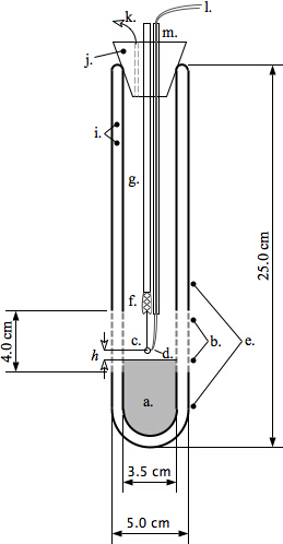 Figure 2. Fused Silica Optical Dewar Setup for Variable Temperature (77-300 K) Cryogenic Luminescence Spectroscopy. This diagram of the optical Dewar illustrates the complete variable temperature system. (a.) liquid nitrogen, (b.) transparent (4.0 cm) unsilvered optical access region of Dewar, (c.) copper sample loop, (d.) thermocouple junction, (e.) silvered region of Dewar, (f.) alligator clip, (g.) wood dowel, (h.) distance between liquid nitrogen level and sample, (i.) evacuated region between inner and outer Dewar walls, (j.) cork stopper, (k.) nitrogen gas vent hole, (l.) thermocouple wires, (m.) thermocouple wires separated and secured to wood dowel with PTFE tape. Please click here to view a larger version of this figure.
Fused silica is non-emissive and provides high optical transmission from the near ultraviolet, through the visible, and out to the near infrared (~200-2,000 nm). The basic concepts operative in the large storage Dewar system described previously10, where sample height above the liquid cryogen determines sample temperature, were successfully carried over on a small scale using this small optical Dewar. However, instead of mechanically adjusting the sample height h above a stationary liquid cryogen level to adjust the sample temperature T, the sample position with respect to the Dewar itself is fixed (Figure 2). The slow boil off of the liquid nitrogen in the optical Dewar over a period of several hours gradually increases the distance h of the sample above the falling liquid nitrogen level (Figure 3).
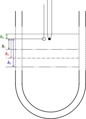 Figure 3. Close up of Sample Region of Optical Dewar. Temperatures: sample immersed in liquid nitrogen to level h0, to give T0 = 77 K; sample immersed in cold nitrogen vapor at levels h1 < h2 < h3 above the liquid nitrogen level to give sample temperatures T1 < T2 < T3. Please click here to view a larger version of this figure.
This allows for a slow, controlled increase in the sample temperature over time (up to several hours) while maintaining both the sample and the temperature probe, a copper-Constantan thermocouple junction, in thermal equilibrium with the cold nitrogen vapor. Luminescence spectra spanning the visible and near-infrared regions are acquired in just a few milliseconds per spectrum (or hundreds of spectra per second) with a CCD-equipped luminescence spectrograph during which sample temperature is virtually constant (ΔT < 0.1 K) as each spectral dataset is acquired. Typical wait times between spectra at temperatures ~5 K apart are ~5-15 min. Moreover, the effects of sample heating or photochemical degradation of the sample by the exciting light are minimized since the excitation light is only allowed to strike the sample a few seconds per spectrum. In the interest of simplicity, portability, and quickness of sample loading, fiber optic cables are not employed. Samples are excited directly with either the 365 nm band from a mercury arc lamp or the 405 nm line of a diode laser. Emitted light from the samples is picked up directly from the emitting sample in the Dewar by a collection lens and impinged on the entrance slit of the spectrograph by a focusing lens. Samples of the ruthenium and rhodium complexes under investigation are prepared for spectroscopic study as thin films of ~10-3-10-4 M solute in oxygen-saturated solutions. The solutions are held by surface tension in small copper wire loops (~3 mm loop diameter formed out of 0.0150 in. dia. copper wire). The thermocouple junction height is then adjusted so it is equal to the sample height (hthermocouple = hsample) and in close proximity to the sample loop as shown in Figures 2 and 3. Temperatures are determined by measuring the voltage difference between the thermocouple sample junction and a 0 °C water/ice thermocouple reference junction using a high-impedance digital voltmeter and comparing to a temperature vs. voltage table for a Type T copper/Constantan thermocouple. The thin-film sample solutions captured in the wire loops are flash frozen by quick immersion in liquid nitrogen in the optical Dewar. Then the frozen solutions are allowed to warm up very gradually over time, remaining frozen, while their luminescence spectra are measured as a function of temperature. The luminescence intensity versus temperature data are analyzed according to the following model.
The total luminescence intensity of the sample at temperature T is given as the sum of the intensities arising from oxygenated and unoxygenated complexes:
![]() . (1)
. (1)
The luminescence intensity from the complexes without oxygen is assumed to be temperature independent. However, the luminescence intensity of the oxygenated complexes will decrease exponentially with increasing temperature due to oxygen quenching. This can be described by an Arrhenius equation of the form
![]() . (2)
. (2)
In Equation (2), Ea is the quenching activation energy and k is the Boltzmann constant. The maximum luminescence intensity will be observed in the low temperature region (see Figure 5), where there is insufficient thermal energy to overcome the quenching activation barrier (i.e., energy transfer from the complex to oxygen). If Equation (2) is substituted into Equation (1), the expression
![]() (3)
(3)
is obtained. In Equation (3), ![]() is the intensity arising from oxygenated complexes in the low temperature region. Rearrangement of Equation (3) yields
is the intensity arising from oxygenated complexes in the low temperature region. Rearrangement of Equation (3) yields
![]() . (4)
. (4)
Taking the natural logarithm of the both sides of Equation (4) gives the expression
![]() . (5)
. (5)
From Equation (5) it is evident that a plot of ![]() versus
versus ![]() will give a straight line with
will give a straight line with ![]() , from which the luminescence quenching activation energy is obtained as
, from which the luminescence quenching activation energy is obtained as
![]() . (6)
. (6)
Protocol
1. Sample Preparation and Loading for Cryogenic Spectroscopy
Prepare ~3 ml of a ~10-3-10-4 M solution of luminescent chromophore in an appropriate solvent. Note: While many solvents can be used, water and various alcohol solvents (e.g., ethanol, ethanol/methanol mixtures, ethylene glycol, and glycerol) provide an excellent combination of solubility and surface tension characteristics for cryogenic work.
Prepare a sample loop by twisting a length of bare copper wire ~0.4 mm in diameter around a nail or screw to give a single loop ~3 mm in diameter followed by an ~30 mm straight length of braided copper wire.
Rinse the sample loop with 95% ethanol to remove finger oils and other contaminants and allow to dry. To ensure cleanliness of the loop, rinse first with nitric acid, second with distilled water, and finally with ethanol.
Load the sample solution into the sample loop by dipping the loop into the sample solution (Step 1.1), letting surface tension of the solution hold a thin film of the solution in the loop.
Immediately dip the loaded sample loop into liquid nitrogen to freeze and stabilize the thin film sample solution in the loop taking care to use eye protection (safety goggles) and hand protection (gloves).
2. Thermocouple Preparation, Alignment and Setup
- Prepare a copper-Constantan (Type T) thermocouple from two lengths of uninsulated 0.4 mm diameter copper wire and one length of 0.4 mm diameter uninsulated constantan (copper-nickel alloy) wire by forming two copper-Constantan junctions: a sample junction and a standard reference junction (0°C ice/water mixture). Note: While the junctions can be silver soldered together, it is completely satisfactory to twist the copper and Constantan wires together to form the junctions.
- Clamp the copper and Constantan wires together with needle-nose pliers at a ~90° angle. While pulling firmly on the two wires, snugly braid them together for five-six turns.
- Arrange all thermocouple wires so they do not touch at any point other than at the two junctions. If the thermocouple wires are covered with a thin insulation coating, they may touch and points other than the junctions.
- When using insulated thermocouple wires, scrape away the insulation at the ends of the wires where the junctions and the electrical contacts with the voltmeter terminals are formed. Be careful to check that the insulation material on the wires does not luminesce. Test the thermocouple wire insulation as a potential source of spurious luminescence by placing a small piece of insulated wire in the sample loop, exciting the sample with light of the chosen wavelength, and looking for an emission signal when no sample is present.
Connect the two copper thermocouple wires from the sample and reference junctions to the input terminals of a high-impedance 5½ digit digital voltmeter.
Place both the sample and reference junctions in the 0 °C water/ice bath and zero the voltmeter.
Align the loaded sample loop and the sample junction of the thermocouple in the liquid-nitrogen-filled optical Dewar to coincide with appropriate height and direction of the excitation light beam. Keep the thermocouple junction and the sample loop as close together as possible and at exactly the same height in the Dewar.
3. General Mechanical Support and Alignment of Sample Loop and Thermocouple Junction in the Optical Dewar
- To align and hold the sample loop in the desired height in the optical Dewar, prepare an adjustable-height holding clamp by affixing a small electrical alligator clip to a 5 mm diameter x 30 mm length wood dowel.
- Bore a hole slightly smaller than 5 mm diameter in a cork that fits snugly into the top of the optical Dewar. Clamp the braided wire section of the sample loop in the alligator clip, then slide the dowel up or down in the cork to achieve the desired sample height in the Dewar.
To align and hold the thermocouple junction at the desired height in the optical Dewar, use another 5-mm diameter wood dowel. Align the thermocouple junction so that it sticks out 10-20 mm below the bottom of the dowel. Align the copper and constantan wires on opposite sides of the dowel and wrap tightly with 12.5 mm-width polytetrafluoroethylene (PTFE) plumber's tape to hold these wires firmly in place.
Bore another hole slightly smaller than 5 mm in diameter in the cork at the top of the Dewar to accommodate this second dowel and allow for vertical height adjustment of the thermocouple junction near the sample loop.
Bore a third small hole in the cork at the top of the Dewar to serve as a nitrogen gas boil off vent hole.
4. Temperature-dependent Cryogenic Spectroscopy in the Optical Dewar
Turn on all electronics on the CCD spectrograph at least 1 hr in advance to allow the electronics to warm up and the Peltier-cooled CCD camera to reach a stable operating temperature.
- After the warm up period is over, wavelength calibrate the CCD spectrograph against a series known atomic emission lines or bands. Measure the spectrum of a low-pressure atomic emission lamp emitting bands of known wavelengths and correlate CCD pixel numbers activated by the bands with the known band wavelengths. Note: In most modern CCD spectrographs, including the Andor CCD spectrograph used in this research, the wavelength calibration process is automated in the software.
- Intensity calibrate the spectrograph by comparing the measured the spectrum of a quartz-halogen lamp operating at 3,200 K to the known spectral profile of the lamp, which closely approximates a 3,200 K black body.
Pre-align the excitation and emission optics to ensure that the excitation light is hitting the sample in the loop and the emitted light from the sample is being collected and impinged upon the entrance slit of the CCD-spectrograph. Note: This is two-step mechanical process. The first step is an initial coarse alignment of the optics to get the emitted light onto the entrance slit of the spectrograph such that a luminescence signal is detected by the CCD. The second step consists of a careful optimization of the sample's luminescence signal strength by systematic adjustments of the positions of the exciting light beam, the Dewar, the sample itself in the loop, and the emission collection optical elements.
Once the optics are aligned and optimized as described in 4.3, measure a 77 K liquid nitrogen reference luminescence spectrum of the sample. For this spectrum, ensure that the frozen thin-film sample in the copper wire loop, the thermocouple adjacent to the loop, the Dewar, the excitation beam, and the emission collection optics are all in their final optimized positions and the sample is completely covered with liquid nitrogen.
Set up the reference junction of the thermocouple on a wood dowel with the wires wrapped in PTFE tape just as the sample junction is. This protects the reference junction and prevents undesirable wire contact.
Verify that the 0 °C reference thermocouple junction is immersed in a water-ice slush. Check the ice level in the reference junction frequently. Set up the reference junction in a small, wide-mouth laboratory Dewar to reduce the rate at which the ice melts.
Check the measured thermocouple voltage at 77 K against the literature voltage at 77 K listed for a Type T copper-Constantan thermocouple. The two thermocouple voltages should be in very close agreement. Make appropriate corrections for pressure (e.g., using the Clausius-Clapeyron equation) if the atmospheric pressure is less than 1 atm.
Allow the liquid nitrogen to boil off slowly. Note: The temperature of the sample rises slowly (over a period of several hours) as the distance h between the sample and the liquid nitrogen level slowly increases as a consequence of liquid nitrogen boil off. The digital voltmeter responds to this temperature rise, providing an accurate temperature measurement since the sample thermocouple junction is fully immersed in cold nitrogen vapor.
- Momentarily turn on or unblock the excitation light and use the CCD spectrograph to acquire a luminescence spectrum using manufacturer's protocol. The spectral data acquisition process should be optimized so that it only takes a few seconds.
- Turn off or re-block the excitation light just as soon as the data acquisition process finishes to minimize errors that arise from unwanted excitation-light-induced sample photochemistry and/or excitation-light-induced sample heating.
- Record the thermocouple voltage at the beginning and end of the spectral data acquisition interval. The thermocouple voltage should not change appreciably (i.e., associated temperature change ΔT within 0.0-0.1 K) during the very short time interval (~1-10 sec) over which the spectral data are acquired at a given temperature. Convert voltage readings to temperatures by referencing a Type T copper-Constantan temperature vs. voltage table.
Allow the liquid nitrogen boil off to continue, and measure another spectrum when the sample temperature has increased by ~5 K. Make no changes in the optics, electronics or excitation light intensity during the course of these temperature-dependent spectral measurements. Note: Depending upon the quality of the optical Dewar, this warm up process takes from 5 to 15 min per ~5 K interval.
- Intensity-correct the CCD spectral data sets by subtracting off the dark frame intensities (i.e., the spectral intensity recorded by the CCD when the entrance slit is blocked) and accounting for wavelength-dependent spectral response. Subtract the baseline dark count intensity count level from each sample spectrum.
- Correct for the wavelength dependent spectral response by measuring the intensity of a standard of known intensity, such as a 3200 K tungsten halogen standard lamp, and using the ratio of the known intensity to the measured intensity to correct the measured intensity of the sample at each wavelength.
Representative Results
Representative results obtained in the above described apparatus for a temperature-dependent luminescence quenching study in the 77-200 K region of the luminescent compound Tris(4,7-dimethyl-1,10-phenanthroline)rhodium(III), [Rh(4,7-Me2-1,10-phen)3]3+, dissolved in oxygen-saturated glycerol are listed in Table 1 and plotted in Figures 4, 5, and 7.
| Temperature (K) | Reciprocal Temperature (1/K) |
|
| 163.02 | 0.006134 | -4.491 |
| 171.69 | 0.005824 | -3.216 |
| 177.30 | 0.005640 | -2.529 |
| 183.46 | 0.005451 | -1.922 |
| 187.15 | 0.005343 | -1.421 |
| 190.80 | 0.005241 | -1.056 |
| 194.39 | 0.005144 | -0.663 |
| 197.94 | 0.005052 | -0.394 |
Table 1. Extent of Quenching vs. Reciprocal Kelvin Temperature for [Rh(4,7-Me 2 -1,10-phen) 3 ] 3+ in Frozen Glycerol Glass.
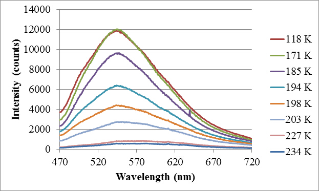 Figure 4.Luminescence Spectra of the Complex [Rh(4,7-Me2-1,10-phen)3]3+ as a Function of Temperature. (a.) maroon = 118 K, (b.) green = 171 K, (c.) purple = 185 K, (d.) turquoise = 194 K, (e.) orange = 198 K, (f.) gray = 203 K, (g.) brown = 227 K, (h.) blue = 234 K. Please click here to view a larger version of this figure.
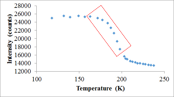 Figure 5. Peak Luminescence Intensities as a Function of Temperature for [Rh(4,7-Me2-1,10-phen)3]3+. Luminescence data subset analyzed for the activation energy computation is boxed in red. Please click here to view a larger version of this figure.
The structure of this complex is shown in Figure 6.
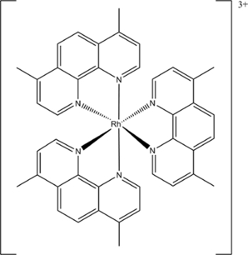 Figure 6. Molecular Structure of LuminescentTris(4,7-dimethyl-1,10-phenanthroline)rhodium(III) Complex, [Rh(4,7-Me2-1,10-phen)3]3+. Me = methyl, phen = phenanthroline, numbers refer to positions of methyl substituents on phenanthroline rings (shown as line segments). Please click here to view a larger version of this figure.
As seen in Table 1 and in Figures 4 and 5, the luminescence intensity remains essentially constant from 77 K to 175 K, then progressively diminishes as temperature increases from 175 K to 240 K.
From Equation (5), a plot of ![]() , a parameter that represents the extent of quenching, vs. the reciprocal Kelvin temperature (1/T) yields a straight line (R2 = 0.9988), from which an oxygen luminescence quenching activation energy of 31.5 kJ/mol is calculated for this complex in the solvent glycerol (see Figure 7).
, a parameter that represents the extent of quenching, vs. the reciprocal Kelvin temperature (1/T) yields a straight line (R2 = 0.9988), from which an oxygen luminescence quenching activation energy of 31.5 kJ/mol is calculated for this complex in the solvent glycerol (see Figure 7).
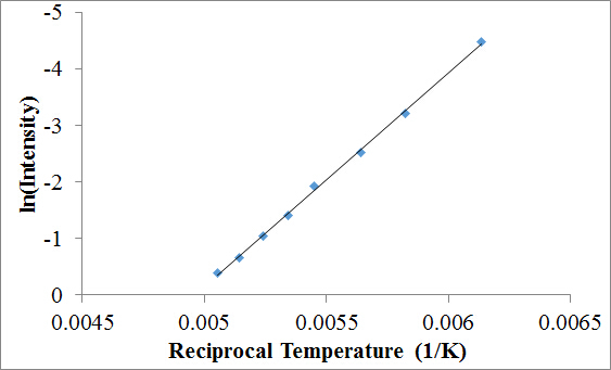 Figure 7. Arrhenius Plot (R2 = 0.998) of the Natural Logarithm of the Extent of Quenching vs. Reciprocal Kelvin Temperature. The luminescent sample is oxygenated ~10-4 M [Rh(4,7-Me2-1,10-phen)3]3+ (Rh = rhodium, Me = methyl, phen = phenanthroline), the solvent is glycerol, and the luminescence quenching activation energy E'a as calculated from the plot is 31.5 kJ/mol; = 0.9988. Please click here to view a larger version of this figure.
In Table 2, Ea values for several other related complexes, as obtained by this method, are listed.
| Compound | Ea (kJ/mol) | R2 |
| [Rh(5,6-Me2-phen)3]3+ | 31.20 | 0.9922 |
| [Rh(4,7-Me2-phen)3]3+ | 31.50 | 0.9980 |
| [Rh(3,4,7,8-Me4-phen)3]3+ | 30.60 | 0.9907 |
| [Ru(2,2’-bipyridyl)3]2+ | 15.27 | 0.9955 |
Table 2. Luminescence Quenching Activation Energies by Oxygen and Values for Rh(III) and Ru(II) Complexes in Glycerol.
While to the best of the authors' knowledge there are no other data to compare directly with these results, the conformation of the experimental data to Equation (5), and to each other for related molecules, provides strong internally consistent evidence that the apparatus and procedure produce accurate, thermally equilibrated sample temperatures which can be successfully analyzed. This evidence, taken in conjunction with direct thermal calibration evidence in the apparatus, indicates that sample temperature is known and constant throughout the sample while the luminescence spectra are being acquired.
Discussion
The development of this apparatus for low temperature luminescence spectroscopy arose out of necessity. It was critical that solutions containing the chromophore of interest and also supersaturated with oxygen could be loaded, frozen, and positioned for spectroscopy all in an instant in a Dewar/cryostat design in which sample temperature was well defined, stable, and slowly changeable. Virtually all commercial cryostats take much more time to load with sample than these experimental constraints would allow. It was also important to have a small, portable Dewar/cryostat to allow facile sample loading/freezing in the upstairs chemistry laboratory followed by transport downstairs to the spectroscopy laboratory. The technique can be applied to virtually any system for which variable low-temperature luminescence measurements are needed. While the technique as described is for sample solutions that are liquids at RT, it can also be extended to samples that are solids at RT. Solid samples can be attached to the sample loop by either by glue or mechanical means.
There are three advantages to be gained by letting the natural boil off of the liquid nitrogen in the Dewar/cryostat slowly change the sample temperature: (a) thermal equilibration of the sample is maintained throughout the temperature range of interest; (b) for a spectral data acquisition process that only takes a few seconds, the sample temperature is virtually constant; and (c) the extremely short luminescence data acquisition time (and thus the extremely short time the sample needs to be excited) minimizes the chances of incurring unwanted excitation-light-induced sample photochemistry and/or sample heating.
Prior to sample loading, the digital voltmeter must be zeroed by placing both the sample and reference thermocouple junctions in a 0 °C = 273.15 K water/ice bath or, alternatively, in 77 K liquid nitrogen. For quantitative luminescence intensity measurements, the excitation source (laser or arc lamp) must be well warmed up and stable in output. The Peltier CCD cooler also must be turned on well in advance of measurements (at least 1-2 hr) to ensure stable operation of the CCD detector. For accurate temperature measurements, care must be taken to position the sample loop and the thermocouple sample junction at exactly the same height h above the liquid nitrogen level in the Dewar. An experiment is performed by starting with the liquid nitrogen level above the level of the sample. No more liquid nitrogen is added to the Dewar during the experiment. In the apparatus as described, the liquid nitrogen is maintained at atmospheric pressure. After the liquid nitrogen level has dropped below the level of the sample, the sample warms up at a rate of ≈ 0.5 - 1 K/min. Spectra are acquired in 1 - 3 sec at ≈ 5 K intervals. Small alterations in the warming rate are induced by changes in laboratory humidity and temperature.
It is important to ensure rigid mounting of the Dewar, sample, and thermocouple throughout the experiment since the slightest movement will give rise to an undesirable measured luminescence intensity or temperature change. The Dewar is mounted so that xyz positioning can be carried out with adjustable optical table components. For high-precision work, the Dewar can be mounted on a xyz optical stage and the sample can be mounted on a goniometer in the Dewar. On high humidity days, care must also be taken to ensure that the optically accessible region of the optical Dewar is not obscured by a thin film of condensation since this will diminish the measured luminescence intensity over time. This problem can be rectified by dispensing a small stream of dry, gaseous nitrogen across the optically transparent regions of the Dewar.
Arguably, the design of the Dewar/cryostat as described could be criticized for not placing the low-temperature thermocouple junction in direct physical contact with the sample in the loop. A direct contact thermocouple design is now under development. However, positioning the thermocouple junction and sample loop at the same height above the liquid nitrogen level in the Dewar/cryostat in very close proximity is designed to maintain ease of sample loading while fulfilling the Zeroth Law of Thermodynamics conditions for accurate temperature measurement: sample at temperature T is in thermal equilibrium with nitrogen vapor at temperature T which is in thermal equilibrium with the thermocouple junction also at temperature T. Monitoring laser/arc lamp excitation intensity throughout the experiment rather than assuming constant intensity would also be a desirable improvement in the protocol. Similarly, CCD detector sensitivity could be checked throughout the experiment with respect to a standard lamp of known constant intensity.
Disclosures
The authors have nothing to disclose.
Acknowledgments
It is a pleasure to acknowledge the Office of the Dean of the School of Arts and Sciences and the Office of the Provost at Concordia University for support of this research. The authors wish to thank G. A. Crosby for his many contributions to this investigation.
References
- Baker DC, Crosby GA. Spectroscopic and magnetic evidence for multiple-state emission from tris(2,2'-bipyridine)ruthenium(II) sulfate. Chem. Phys. 1974;4(3):428–433. [Google Scholar]
- Crosby GA. Spectroscopic investigations of excited states of transition metal complexes. Acc. Chem. Res. 1975;8(7):231–238. [Google Scholar]
- Hager GD, Watts RJ, Crosby GA. Charge transfer excited states of ruthenium(II) complexes II. Relationships of level parameters to molecular structure. J. Am. Chem. Soc. 1975;97(24):7037–7042. [Google Scholar]
- Elfring WH, Crosby GA. Excited states of mixed-ligand chelates of ruthenium(II) and rhodium(III) J. Phys. Chem. 1976;80(20):2206–2211. [Google Scholar]
- Elfring WH, Crosby GA. Excited states of mixed-ligand chelates of ruthenium(II). Quantum yield and decay time measurements. J. Am. Chem. Soc. 1976;103(10):2683–2687. [Google Scholar]
- Fordyce WA, Rau H, Stone ML, Crosby GA. Multiple state emission from rhodium(I) and iridium(I) complexes. Chem. Phys. Lett. 1981;77(2):405–408. [Google Scholar]
- Pankuch B, Crosby GA. Spectroscopic measurements of solutions and rigid glasses. Chem. Instrum. 1970;2(3):329–335. [Google Scholar]
- Landee CP, Greeney RE, Lamas AC. Improved helium cryostat for a vibrating sample magnetometer. Rev. Sci. Instrum. 1987;58(10):1957–1958. [Google Scholar]
- Fairman RA, Spence KVN, Kahwa IA. A simple liquid nitrogen gas-flow cryostat for variable temperature laser luminescence. Rev. Sci. Instrum. 1994;65(2):503–504. [Google Scholar]
- Meyer GD, Ortiz TP, Costello AL, Kenney JW, Brozik JA. A simple fiber-optic coupled luminescence cryostat. Rev. Sci. Instrum. 2002;73(12):4369–4374. [Google Scholar]


