Abstract
A method is demonstrated to monitor macroscopic translational diffusion using electron paramagnetic resonance (EPR) imaging. A host-guest system with nitroxide spin probe 3-(2-Iodoacetamido)-2,2,5,5-tetramethyl-1-pyrrolidinyloxy (IPSL) as a guest inside the periodic mesoporous organosilica (PMO) aerogel UKON1-GEL as a host and ethanol as a solvent is used as an example to describe the protocol. Data is shown from a previous publication, where the protocol has been applied to both IPSL and Tris(8-carboxy-2,2,6,6-perdeutero-tetramethyl-benzo[1,2-d:4,5-d′]bis(1,3)dithiole) methyl (Trityl) as guest molecules and UKON1-GEL and SILICA-GEL as host systems.
A method is shown to prepare aerogel samples that cannot be synthesized directly in the sample tube for measurement due to a size change during synthesis. The aerogel is attached to sample tubes using heat shrink tubing and a pressure cooker to reach the necessary temperature without evaporating the solvent in the process. The method does not assume a clearly defined initial distribution of guest molecules at the start of the measurement. Instead, it requires a reservoir on top of the aerogel and experimentally determines the influx rate during data analysis.
The diffusion is monitored continually over a period of 20 hr by recording the 1d spin density profile within the sample. The spectrometer settings for the imaging experiment are described quantitatively. Data analysis software is provided to take the resonator sensitivity profile into account and to numerically solve the diffusion equation. The software determines the macroscopic translational diffusion coefficient by least square minimization of the difference between the experiment and the numerical solution of the diffusion equation.
Keywords: Chemistry, Issue 115, EPR imaging, diffusion, porous media, periodic mesoporous organosilica, nitroxide, host-guest interaction
Introduction
Porous materials play a major role in practical applications such as catalysis and chromatography1. By adding surface groups and adjusting the pore size and surface properties, the materials can be tailored to the desired application2,3. The functionality of the porous material crucially depends on the diffusion properties of the guest molecules inside the pores. In porous materials, a distinction must be made between the microscopic translational diffusion constant Dmicro, which describes diffusion on a molecular length scale on one hand and the macroscopic translational diffusion constant Dmacroon the other hand, which is influenced by the diffusion through multiple pores, grain boundaries, tortuosity and inhomogeneity of the material.
There are several magnetic resonance methods available to study diffusion, each suitable for a particular length scale. On the millimeter scale, nuclear magnetic resonance (NMR) imaging4 and electron paramagnetic resonance (EPR) imaging (as presented in this protocol) can be used. Smaller scales become accessible by the use of pulsed field gradients in NMR as well as EPR experiments5,6. On the nanometer scale, EPR spectroscopy can be used by observing changes of the Heisenberg exchange interaction between spin probes7,8. Studies of translational diffusion using EPR imaging range from industrial catalyst supports, e.g., aluminum oxide9, to anisotropic fluids10,11, drug release systems made of polymer gels12-14 and model membranes15.
This protocol presents an in situ approach using EPR imaging to monitor macroscopic translational diffusion of spin probes in cylindrical, porous media. It is demonstrated for a host-guest system consisting of the nitroxide spin probe 3-(2-Iodoacetamido)-2,2,5,5-tetramethyl-1-pyrrolidinyloxy (IPSL) as a guest inside the periodic mesoporous organosilica (PMO) aerogel UKON1-GEL as a host and ethanol as a solvent. This protocol has successfully been used previously16 to compare Dmacro as determined with EPR imaging with Dmicro for the host materials UKON1-GEL and SILICA-GEL and guest species IPSL and Tris(8-carboxy-2,2,6,6-perdeutero-tetramethyl-benzo[1,2-d:4,5-d′]bis(1,3)dithiole) methyl (Trityl), see Figure 1.
In other methods based on continuous wave (CW) EPR imaging17, diffusion takes place outside of the spectrometer. In contrast, the method presented here uses an in situ approach. A series of snapshots of the 1d spin density distribution ρ1d (t, γ) is recorded over a period of several hours. During this time, one snapshot is taken after the other and delivers a real-time diffusion pattern with a time resolution of approximately 5 min.
UKON1-GEL and SILICA-GEL have been synthesized in sample tubes with an inner diameter of 3 mm as described in literature.16,18,19 The UKON1-GEL and SILICA-GEL synthesis leads to a shrinking of the sample. The samples are placed inside a heat-shrink tube to prevent guest molecules from moving between the aerogel and the wall of the sample tube. This additional step is not necessary for samples that can be synthesized directly in the sample tube without changing their size. The aerogel samples collapse when they dry out, so they must be submerged in solvent at all times. The temperature that is needed for the heat shrink tubing is higher than the boiling point of ethanol at ambient pressure. Therefore the protocol describes the use of a pressure cooker to raise the boiling point of ethanol.
The protocol covers the sample preparation of UKON1-GEL synthesized beforehand for the EPR imaging experiment and the spectrometer settings that are used to monitor diffusion of IPSL spin probe. For data analysis, locally written software is provided and its use is described. The raw data from the spectrometer can be directly loaded. The software calculates the spatial 1d spin density distribution ρ1d (t, γ) and takes into account the resonator sensitivity profile. The user can select a region of the aerogel and a time window, over which the diffusion constant is to be determined. The software then determines the boundary conditions of the diffusion equation based on that selection and solves the diffusion equation. It supports least square fitting to find the value of Dmacro where the numerical solution best matches the experimental data.
The protocol can be used with adjustments for different guest and host materials as long as the cross sectional area of the sample does not change throughout the sample, that is ρ1d (t, γ) gives direct access to the concentration and is not influenced by a change in sample cross section. The range of accessible values for Dmacro is estimated16 between 10-12 m2/sec and 7·10-9 m2/sec.
Protocol
Caution: Please consult all relevant material safety data sheets (MSDS) before use. Ethanol is harmful if swallowed or inhaled and it is flammable.
1. Optimize the Continuous Wave (CW) EPR Parameters
Prepare 40 µl of IPSL in ethanol (p.a.) at a concentration of 1 mM.
Take a pipette controller and fill a capillary with the IPSL solution to a filling height of 2 cm. Pull the solution 1 cm further into the capillary so that there is an air gap below the solution. Seal the capillary on both ends with capillary tube sealing compound. The air gap prevents diffusion of components of the sealing compound into the sample.
Wrap two strips of polytetrafluoroethylene (PTFE) tape of about 5 cm length around the capillary at a distance of 1 cm from the upper and lower end of the capillary.
Put the capillary into an EPR sample tube (4 mm inner diameter). Make sure that the PTFE tape keeps the capillary fixed in the center axis of the sample tube. Push the capillary down to the bottom of the sample tube.
Put the sample into the resonator and center the spin label solution within the resonator.
Tune the spectrometer for critical coupling by following the instructions in the spectrometer manual.
- Preliminary Spectrometer Settings
- Use the microwave frequency to set the center field B using the formula
 where g ≈ 2.003 is a rough estimate for the g factor of the unpaired radical in the nitroxide spin label, h is the Planck constant and μB is the Bohr magneton.
 - Set up a new experiment "field_sweep" with the magnetic field as abscissa and the signal intensity as ordinate. Use the following parameters: Centerfield as calculated in the previous step, sweep width: 400 G, modulation amplitude: 0.8 G, modulation frequency: 100 kHz, microwave attenuation: 30 dB, number of points: 2,048, number of scans: 1, scan time: 80 sec, time constant: 50 msec.
- Activate the Setup Scan mode. For the Setup Scan Time Constant, select the lowest value that the spectrometer offers. Adjust the receiver gain to a value where the displayed signal fills 80% of the displayed intensity range, so that even with noise no data point has a higher intensity than 80% of the maximum. Disable Setup Scan afterwards.
- Press the "Run" button.
- Read the field value of the zero crossing of the central peak from the spectrum obtained. Set the center field to that value.
- Take the horizontal line tool and measure the spectrum width from the point where the leftmost peak starts to rise above the baseline level to the point where the rightmost peak returns to the baseline level.
- Set the sweep width to three times the spectrum width.
- Recalculate the Spectrometer Parameters
- Calculate the sweep time: sweep width/sweep speed. Use a sweep speed of 5 G/sec.
- Calculate the minimum number of data points: 10 * sweep width/line width.
- Calculate the conversion time: sweep time/number of data points.
- Calculate the time constant: 0.1 * line width * scan time/sweep width.
- Measure a Saturation Curve to Determine the Optimum Microwave Power
- Set the microwave attenuation to 10 dB and adjust the receiver gain as described in step 1.7.3.
- Set the microwave attenuation to 50 dB and record a spectrum. If the signal to noise ratio is less than 5:1, increase the number of scans. Repeat this step until the signal to noise ratio is 5:1 or greater.
- Create a new experiment "saturation" using the magnetic field as abscissa 1, the microwave power as abscissa 2 and the signal intensity as ordinate. Copy all settings from the "field_sweep" experiment from step 1.9.2. For abscissa 2, set the start value of the microwave attenuation to 10 dB, the increment value to 1 dB and the number of points to 41 to cover a range from 10 dB to 50 dB. Run the experiment.
- Create a spreadsheet for the saturation curve. Insert the microwave attenuation in dB into the first column.
- Calculate the square root of the microwave power in a.u. in the second column with the formula
 where x is the microwave attenuation in dB from the first column.
 - Use the spectrometer software to measure the peak to peak intensity of the central spectral line for each microwave attenuation in the experiment. Write that intensity into the third column in the spreadsheet.
- Plot the square root of the microwave power against the peak to peak intensity (column 3 against column 2) to get the saturation curve. Include the origin (0,0) in the plot.
- Identify the linear regime of the saturation curve. The optimal microwave power is the highest microwave power that is still in the linear regime. Use the corresponding attenuation setting for all further experiments.
2. Determine the Magnetic Field Gradient Strength and the Time Resolution
Create a new experiment in the spectrometer software with the magnetic field as abscissa 1 and the signal intensity as ordinate. Enable the gradient coil controls.
Copy all spectrometer settings from the previous experiment as determined in 1.8 and 1.9.8.
Set the magnetic field gradient strength to 170 G/cm in the direction of the sample axis pointing upwards.
Calculate the sweep width sw = sw0 + FOV·G, where sw0 is the sweep width determined in 1.8.4 in the absence of a magnetic field gradient, FOVis the field of view (2.5 cm) and G is the magnetic field gradient strength.
Calculate the estimated pixel size = line width / G, using the line width of the spectrum recorded in 1.9.3 in the absence of a magnetic field gradient.
Calculate the sweep time = sw / sweep speed. Use the same sweep speed as in 1.8.1.
Calculate the minimum number of data points required using the higher value of i. N1= 10 * sweep width / line width ii. N2 = 10 * field of view / (G * pixel size).
Calculate the conversion time: sweep time/number of data points.
Calculate the time constant: 0.1 * line width * scan time / sweep width or lower.
Set the parameters calculated in 2.3 through 2.9 and press the "Run" button.
Measure the noise level of the baseline as well as the peak to peak intensity of the central line with the vertical line tool. Calculate the signal to noise ratio.
If the signal to noise ratio is less than 5:1, double the number of scans in the "scan" panel of the spectrometer parameters and repeat steps 2.1.3 through 2.11.
3. Prepare the Sample
Caution: Wear safety glasses.
Note: Keep the aerogel completely submerged in solvent at all times. See Figure 2 for a photograph and schematic.
Fill a Petri dish of 10 cm diameter with ethanol (p.a.) up to a height of 5 mm.
Put the aerogel into the Petri dish and cut off a cylindrical piece of 5 mm to 1 cm in length.
Prepare a piece of heat shrink tubing that is about 1 cm longer than the aerogel cylinder.
Use a glass tubing cutter to break a sample tube of 2 mm inner diameter to create two pieces of 4 cm length. Both pieces should have two open ends. Caution: Wear safety glasses and appropriate gloves when operating the heat gun. Do not direct the airflow towards skin or clothing and keep it away from flammable materials.
- Insert one of the sample tube pieces 5 mm deep into one end of the heat shrink tubing. Use a heat gun to carefully heat this end of the heat shrink tubing without shrinking the rest of the tubing. The heat shrink tubing should now be fixed at the glass tube.
- Submerge this combination of glass tube and heat shrink tubing in the Petri dish of the aerogel. Carefully push the piece of aerogel from step 3.2 into the open end of the heat shrink tubing.
Fill a test tube with ethanol (p.a.) up to a height of 7 cm. Transfer the sample from the Petri dish into the test tube. While doing so, make sure that the open end of the heat shrink tubing is oriented to the top. Make sure that the aerogel is completely submerged in ethanol.
Insert the second 4 cm long piece of sample tube from step 3.4 into the open end of the heat shrink tubing. Do not apply force, gravity should be enough to close the gaps between the aerogel and the sample tube pieces. Put the test tube with the sample into a beaker.
Fill a pressure cooker with at least 500 ml ethanol and add a stir bar.
Put the beaker containing the sample on a trivet inside the pressure cooker. Caution: Perform the next step under a fume hood and continue to wear safety glasses.
Cook and stir the samples at a pressure setting of 1 bar above ambient pressure on the magnetic stirrer. The temperature must reach at least 90 °C. Let it cool down as soon as the pressure is reached and the pressure valve releases ethanol vapor. If the heat shrink tubing did not shrink, repeat this step. Note: Immediately clean the pressure cooker with water to minimize the effect of ethanol on the seal valves. At this point, the prepared sample can be stored in ethanol for several months.
4. Prepare the Spectrometer
Create a 2d experiment using the magnetic field as abscissa 1, time as abscissa 2 and signal intensity as ordinate, so that a magnetic field sweep is recorded for each time step. Enable the gradient coil controls.
Set the time delay between measurements to zero. Set the other parameters as determined in section 2. Set the number of points for the time axis to 20 hr/sweep time. Set the microwave bridge to perform a fine tune after each slice scan.
Follow the steps in section 1.7 to tune the spectrometer to the empty resonator.
5. Prepare the Sample for Measurement
Note: The only time critical steps of this protocol are 5.3 through 6.2, which is from the start of the diffusion process with the addition of the spin label until the time the data acquisition in the spectrometer starts. Perform these steps without introducing any delays.
Put a finger on top of the sample from section 3 to keep the ethanol solution from flowing out on the bottom. Then use a syringe to remove some ethanol from the bottom 5 mm of the lower sample tube and seal that end with tube sealing compound. Make sure that there is an air bubble of 2 mm in height above the sealing compound.
Remove all ethanol from the sample tube above the aerogel except for 3 mm just above the aerogel using a Pasteur capillary pipette.
Inject 20 µl of spin label solution in ethanol on top of the aerogel. Make sure to not create an air bubble on top of the aerogel. Mark the current time as start of the diffusion process.
Place the sample in a sample tube with 4 mm inner diameter. Use PTFE tape to center the sample.
Use a felt-tip pen to mark the outer sample tube at a position of 68 mm above the upper edge of the aerogel. This helps in correctly centering the sample in the resonator and puts the center of the resonator 1 mm below the upper edge of the aerogel.
6. Perform the Diffusion Experiment
Place the sample in the resonator so that the marking from 5.5 aligns with the top of the PTFE holder of the resonator and tune the spectrometer for critical coupling as is described in the operating manual of the spectrometer.
Use the Setup Scan mode to set the receiver gain as described in 1.7.3 while the gradient coils are still turned off.
Start the experiment that has been set up in section 4. Write down the current time. Either wait 20 hr for the experiment to finish or stop the experiment when the recorded signal does not change over the course of 4 hr or more. Save the result.
7. Perform Additional Experiments Needed for Data Analysis
Note: Conduct the experiments in 7.1 and 7.2 with the same sample directly after the diffusion experiment and without moving the sample.
- Record the Point Spread Function for Deconvolution
- Switch to the “field sweep” experiment from step 1.7.2. Copy all settings from the experiment in step 6.
- Record a spectrum and measure the signal to noise ratio. If it is less than 20:1, increase the number of scans and repeat this step. Otherwise save the spectrum.
- Perform a 2d Imaging Experiment
- Create a new experiment on the spectrometer with the magnetic field as abscissa 1, the angle of the magnetic field gradient as abscissa 2 and the signal intensity as ordinate. Copy the parameters from step 6. Set the imaging plane to the YZ plane, which is the plane including the direction of the static magnetic field B0 and the sample axis.
- Set the number of angles N of the gradient direction to N = FOV/desired pixel size or higher.
- Start the measurement and save the result.
- Repeat the steps in 7.1 and save the result.
- Measure the Resonator Sensitivity Profile
- Prepare another sample of spin probe in solution by repeating steps 1.1 through 1.5, but this time add 4 cm of the solution into the capillary instead of 2 cm.
- Follow the steps in section 2 to record a spectrum of the sample with a magnetic field gradient in the direction of the sample axis. For step 2.3, use a field of view of 3 cm. Save the result.
- Repeat the measurement in the absence of the magnetic field gradient and save the result.
8. Data Analysis
- Reconstruct the 2d Imaging Experiment
- Load the 2d imaging experiment from 7.2.3 into the primary viewport of the spectrometer software.
- Load the experiment from 7.2.4 into the secondary viewport of the spectrometer software.
- Go to Processing>Transformations>Deconvolution, select Slice: all and click apply to perform a deconvolution.
- Save the deconvolved data to disk.
- Use the freely available image reconstruction software20 with the following command: reconstruct --input result_from_8_1_4.DSC --output reconstructed_image.DSC --steps 100 --size 256
- Load the result from 8.1.5 into the spectrometer software for later reference.
- Analyze the Recorded Diffusion Experiment
- Start the data analysis software and go to the "Load" tab of the software shown in Figure 3. Load the diffusion experiment from step 6.3 under "diffusion experiment". Load the corresponding point spread function from step 7.1.2 under "diffusion experiment w/o gradient". Load the result from step 7.3.2 under "resonator profile experiment" and the result from step 7.3.3 under "resonator profile exp w/o gradient".
- Go to the resonator sensitivity tab shown in Figure 4 to perform a deconvolution of the data from experiment 7.3.2 using 7.3.3 as point spread function. Decrease the noise power value until the result is noisy, then raise it until the noise just disappears.
- Go to the 1d spin density profile tab shown in Figure 5 in order to deconvolve each field sweep recorded in 6.2 using the experiment from 7.1 as point spread function. Decrease the noise power value until the result is noisy, then raise it until the noise just disappears.
- Switch to the crop area tab shown in Figure 6. Select an area of the diffusion heat map that lies completely inside of the aerogel and where spin probe is just about to enter from above at the first time step of that area. If in doubt, load the reconstructed image from 8.1.6 in the spectrometer software to help identify the exact position of the aerogel.
- Increase the area from step 8.2 in the downward direction of the sample so that no spin probe reaches the lower boundary of the area within the time of the experiment. See Figure 6 for reference.
- Switch to the influx tab shown in Figure 7 and press fit. The left hand panel shows the integral of the cropped region from 8.2.5 along the position axis.
- Verify that the curve shown in the middle panel starts at zero and immediately starts to rise. If that is not the case, go back to 8.2.5.
- Verify that the red line shown in the middle panel follows the black data points.
- Simulate the 1d Spin Concentration Over Time and Fit the Diffusion Coefficient
- Switch to the diffusion coefficient tab and press fit.
- Wait for the results of the calculation.
- Verify that the experimental data shown on the left matches the numerical data shown on the right.
- Read the value of the macroscopic translational diffusion coefficient Dmacro that is displayed on the screen.
Representative Results
A photo and schematic of an aerogel within the shrinking tube is shown in Figures 2a and 2b. The 2d EPR image in Figure 2c clearly shows the upper edge of the aerogel. The intensity of ρ1d within the sample tube above the aerogel is lower although the concentration of the spin probe is at least as high as within the aerogel. However, the sample depth perpendicular to the picture plane is much smaller due to the smaller inner diameter of the sample tube. Note that the EPR image also shows no air bubble in the sample tube and the aerogel does not seem to have any fissures introduced during the shrinking of the shrinking tube.
Figure 8a shows a diffusion heat map of Trityl in UKON1-GEL. Figure 8c shows the same data for IPSL in UKON1-GEL. Figuress 8b and 8d show the numerical solutions for the diffusion equations that match the experimental data from (a) and (c), respectively. Each vertical slice of the heat map shows the concentration profile of the spin probe at a fixed point in time. At the beginning of the experiment the spin probes are concentrated at the top of the sample. As time increases, they propagate through the sample while new spin probes enter from the top. The heat maps show qualitatively that the macroscopic translational diffusion of Trityl is significantly slower than the macroscopic translational diffusion of IPSL. This is to be expected since Trityl is larger than IPSL and the pore system and solvent are the same.
The macroscopic translational diffusion coefficients for Trityl and IPSL in UKON1-GEL and SILICA-GEL are shown in Figure 9. For comparison, Figure 9 also shows the microscopic translational diffusion coefficient for IPSL in ethanol at 2.1·10-10 m2/sec, which has been derived by fitting the spectral line shape from step 7.1.2 using software21 to determine the rotational correlation time as described in a previous article16. The quantitative analysis of Dmacro shows slower diffusion for the larger Trityl molecule compared to IPSL. A comparison between UKON1-GEL and SILICA-GEL shows very similar values for Dmacro. This was expected, since the pore structure of the aerogels is similar and the interaction between the spin probes and the surface groups present in UKON1-GEL is not sufficiently strong to significantly influence Dmacro. Adding glycerol to the solvent increases the viscosity and shows a further decrease of the diffusion coefficient for Trityl. The experiments for Trityl in UKON1-GEL and SILICA-GEL have been repeated with samples from the same batch. The error bars show the standard deviation of Dmacro.
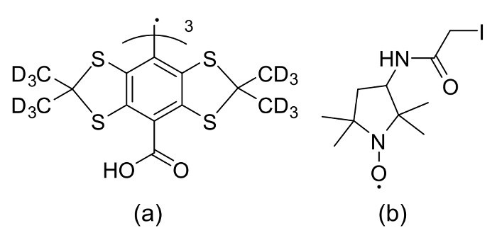 Figure 1:Structural formulas of spin probes. The structural formula of (a) Trityl spin probe and (b) IPSL probe. Reprinted with permission from the American Chemical Society16. Please click here to view a larger version of this figure.
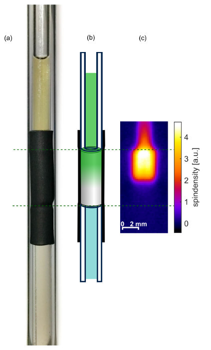 Figure 2:Prepared sample. (a) Photograph, (b) schematic drawing and (c) 2d spin density image 29 hr after injecting the spin probes on top of the aerogel. Reprinted with permission from the American Chemical Society16. Please click here to view a larger version of this figure.
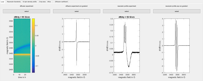 Figure 3:Software screenshot of loading the data. The figure shows the load screen of the software used for data analysis (step 8.2.1). Load the following data from left to right: Raw data from the diffusion experiment (step 6), corresponding point spread function (step 7.1), field sweep for a capillary filled with spin probe in the presence of a magnetic field gradient along the sample axis (7.3.2) and the corresponding point spread function (step 7.3.3). Please click here to view a larger version of this figure.
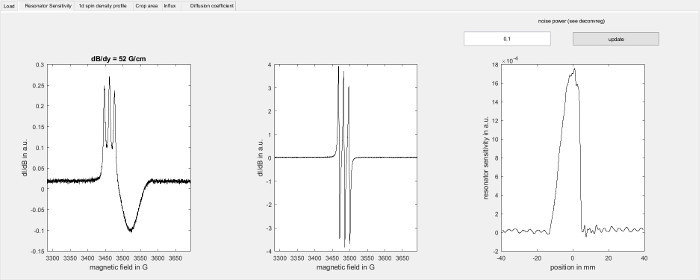 Figure 4:Determination of the resonator sensitivity profile. The figure shows the resonator sensitivity screen of the software used for data analysis (step 8.2.2). On the left, it shows the field sweep for a capillary filled with the spin probe recorded in the presence of a magnetic field gradient along the sample axis (7.3.2) and in the middle it shows the corresponding point spread function (step 7.3.3). On the right the resonator sensitivity profile along the sample axis is shown as determined by deconvolution using the Matlab function deconvreg with the indicated noise power parameter. Please click here to view a larger version of this figure.
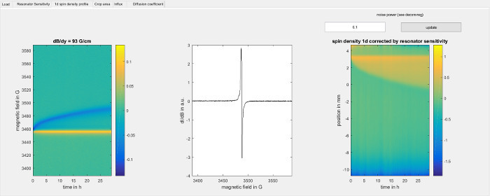 Figure 5:Experimental data for the 1d spin density within the sample. The figure shows the 1d spin density profile screen of the software used for data analysis (step 8.2.3). On the left, it shows the intensities from the diffusion experiment (step 6) in arbitrary units. Each vertical line corresponds to a point in time and is the convolution of the spectral line shape of the Trityl spin probe and the 1d spin density profile, weighted by the resonator sensitivity profile. The gradient direction is along the sample axis from down to up, so that lower points in space give a signal at higher magnetic field and vice versa. The yellow line is created by the top of the sample, where the sample tube touches the aerogel and the diameter of the spin probe solution jumps from the inner diameter of the sample tube to the larger diameter of the aerogel. The blue line is formed by those spin probes that have advanced furthest into the aerogel due to diffusion. The middle panel shows the spectral line shape of the spin probes that is used for deconvolution. The right hand panel shows the color encoded 1d spin sensitivity profile along the sample axis over time, as determined by deconvolution using the Matlab function deconvreg with the indicated noise power parameter for each point in time. The magnetic field axis has been converted to a spatial position axis using the magnetic field gradient strength, where positive values correspond to the top of the sample and negative values correspond to the bottom of the sample. The top of the aerogel can be seen as a horizontal line at about 3.5 mm. Below that line, the propagation of spin probes through the aerogel can be seen as a broadening of the yellow region in the vertical direction as time increases. Please click here to view a larger version of this figure.
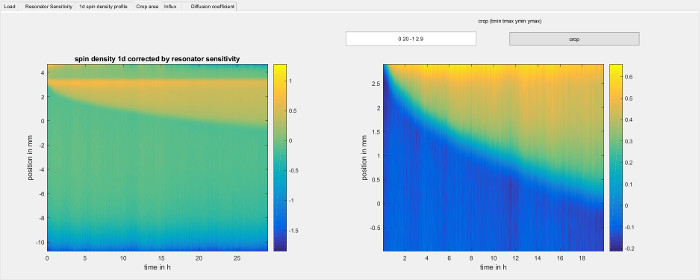 Figure 6:Cropping the 1d spin density to a region of interest. The figure shows the crop area step of the software used for data analysis (step 8.2.4). It shows the 1d spin density from step 8.2.3 on the left hand side. The data is taken directly from the right hand side panel of Figure 5 and is limited to the region where the resonator sensitivity profile is larger than 10 percent of its maximum value. The right hand side shows the same data, but cropped to the area that the user has selected. The diffusion coefficient will be determined from only that area. Please click here to view a larger version of this figure.
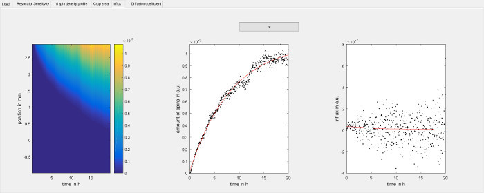 Figure 7:Determine the influx rate of spin probes over time. The figure shows the spin probe influx step of the software used for data analysis (step 8.2.6). Each vertical slice in the panel on the left hand side is the integral function of the 1d spin density with respect to position for each point in time. Negative values have been changed to zero. The center panel shows the amount of spins within the observed area for each point in time as individual data points and is determined by the uppermost row of the panel on the left hand side. The red line is an exponential fit of the data. The panel on the right hand side shows the time derivative of the data in the center panel and corresponds to the influx of spin probe over time. To avoid noise introduced by the numerical derivative of the experimental data, the red line has been calculated analytically from the parameters of the exponential fit of the center panel and it is used as boundary condition to solve the diffusion equation in step 8.2.7.1. The panel on the left hand side is normally not needed but can be used to verify the intermediate data used by the software. Please click here to view a larger version of this figure.
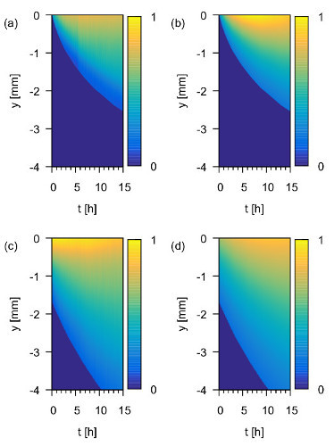 Figure 8: 1d spin density over time. Experimentally measured ρ1d (t,y) in arbitrary units in UKON1-GEL for (a) Trityl and (c) IPSL solutions and numerical solutions of the diffusion equation in (b), (d), respectively. Reprinted with permission from the American Chemical Society16. Please click here to view a larger version of this figure.
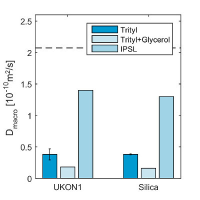 Figure 9:Obtained diffusion coefficients. Experimentally obtained macroscopic translational diffusion coefficients Dmacro. The standard deviation of several measurements using individual samples from the same batch is displayed. The microscopic translational diffusion coefficient Dmacro of IPSL is indicated as a dashed line for comparison with an estimation of the uncertainty of the determination of the rotational correlation time in spectral simulations, indicated as dotted lines16. Reprinted with permission from the American Chemical Society16. Please click here to view a larger version of this figure.
Discussion
The protocol allows monitoring of the diffusion of paramagnetic guest molecules. A 1d imaging approach has been chosen because it allows for a higher time resolution compared to 2d or 3d imaging. The 1d approach requires a constant cross sectional area of the sample because the intensity of the obtained 1d image depends not only on the concentration but also on the cross sectional area of the sample. The method also requires that the EPR spectra of the spin probes within the samples only change in intensity but not in shape. Otherwise more time consuming spectral-spatial imaging must be used, which is outside the scope of this protocol. The method is also limited to systems where Dmacro lies between 10-12 m2/sec and 7·10-9 m2/sec if the sample is observed in an area between 1 mm and 1 cm in length and over time periods between 1 hr and 72 hr16.
Although the UKON1-GEL and SILICA-GEL have been synthesized in a sample tube, the samples contract during the process. This creates a gap between the aerogel and the wall of the sample tube, which prohibits a 1d imaging approach to monitor the diffusion. This complication has been solved by putting the aerogel inside heat-shrinking tube. Samples that do not feature a gap between the aerogel and the sample tube can be measured directly. The 2d imaging experiment serves as a control experiment to check for a spin probe that is outside of the heat-shrinking tube due to leakage. The 2d image can be reconstructed with the filtered back projection algorithm that is implemented in the spectrometer software. In this protocol however the use of an iterative algorithm20, that is more robust in noisy conditions, is suggested.
In previous works10-15,17 that use EPR imaging to study diffusion, the initial state of the experiment is carefully prepared to initially feature a certain amount of spin probes in as small an area as possible and with a completely isolated sample. For the method that is described in this protocol, the initial distribution of spin probes is not critical, as long as there is a part of the sample that initially does not contain spin probes. The amount of spin probes that enters the observed part of the sample is determined directly from the measurement of the diffusion data. The data analysis software implements the method that is described in previous work16. While the spectrometer software includes all the functions that are required to perform the preprocessing steps in 8.2, these steps have been included in the provided data analysis software. This makes it easier to change and compare the choice of parameters.
When adapting the protocol for different sample systems and equipment, the spectroscopic parameters such as scan speed, modulation amplitude, modulation frequency and microwave power need to be adjusted according to the manual of the spectrometer, and also the gradient strength and the time period over which the diffusion is observed needs to be reevaluated. The time duration over which diffusion is observed in step 6.3 depends on Dmacro. The experiment can be stopped when no significant change of the 1d concentration profile occurs. This can also be seen in the raw data before deconvolution.
There are a few critical points to observe when following the steps of this protocol. The particular aerogels used in this protocol collapse and shrink irreversibly when they dry out, so it is crucial to keep the aerogels submerged in solvent at all times. The reason why the pressure cooker is filled with additional solvent and a stir bar in 3.8 is to quickly create vapor pressure before the solvent around the aerogel evaporates. When the aerogels dry out they significantly reduce in diameter and length and a fresh sample must be prepared. The capillary tube sealing compound can result in an EPR signal if it is in direct contact with the solvent and diffuses into the resonator. The air bubble between the sealing compound and the solvent in step 5.1 creates a barrier to prevent this from happening.
Depending on the solvent and the geometry of the sample it can be difficult to achieve critical coupling during the spectrometer tuning step. In that case, rotate the sample and try again, or take the sample out and verify that the aerogel and the capillaries that contain the solvent are centered.
During data analysis in step 8.2.8, the experimentally determined influx of the spin label can deviate from the fit. If that is the case and the signal to noise ratio of the deconvolved data is insufficient, redo steps 8.2.2 and 8.2.3 and increase the noise power parameter to reduce the amount of noise at the cost of spatial resolution. If the signal to noise ratio is not the problem, redo steps 8.2.4 through 8.2.8 to reselect the region from which Dmacro is calculated and make sure that the experimental data as well as the fit in the middle panel of the spin probe influx tab is a line through the origin, as is shown in Figure 7.
Disclosures
The authors have nothing to disclose.
Acknowledgments
The authors thank Prof. Peter Imming and Diana Müller for synthesis of the Trityl spin probe and Prof. Sebastian Polarz, Martin Wessig and Andreas Schachtschneider for the synthesis of the porous materials. Financial support by the DFG (DR 743/7-1) and within the SPP 1570 is gratefully acknowledged.
References
- Schüth F, Sing KSW, Weitkamp J. Handbook of Porous Solids. Weinheim, Germany: Wiley-VCH Verlag GmbH; 2002. [Google Scholar]
- Hoffmann F, Cornelius M, Morell J, Fröba M. Silica-Based Mesoporous Organic-Inorganic Hybrid Materials. Angew. Chem. Int. Edit. 2006;45(20):3216–3251. doi: 10.1002/anie.200503075. [DOI] [PubMed] [Google Scholar]
- Sanchez C, Boissière C, Grosso D, Laberty C, Nicole L. Design, Synthesis, and Properties of Inorganic and Hybrid Thin Films Having Periodically Organized Nanoporosity. Chem. of Mat. 2008;20(3):682–737. [Google Scholar]
- Le Bihan D, Johansen-Berg H. Diffusion MRI at 25: Exploring brain tissue structure and function. NeuroImage. 2012;61(2):324–341. doi: 10.1016/j.neuroimage.2011.11.006. [DOI] [PMC free article] [PubMed] [Google Scholar]
- Pregosin PS, Kumar PGA, Fernández I. Pulsed Gradient Spin−Echo (PGSE) Diffusion and 1H,19F Heteronuclear Overhauser Spectroscopy (HOESY) NMR Methods in Inorganic and Organometallic Chemistry: Something Old and Something New. Chem. Rev. 2005;105(8):2977–2998. doi: 10.1021/cr0406716. [DOI] [PubMed] [Google Scholar]
- Talmon Y, et al. Molecular diffusion in porous media by PGS ESR. Phys. Chem. Chem. Phys. 2010;12(23):5998–6007. doi: 10.1039/b922060g. [DOI] [PubMed] [Google Scholar]
- Okazaki M, Seelan S, Toriyama K. Condensation process of alcohol molecules on mesoporous silica MCM-41 and SBA-15 and fumed silica: a spin-probe ESR study. Appl. Magn. Reson. 2009;35(3):363–378. [Google Scholar]
- Wessig M, Spitzbarth M, Drescher M, Winter R, Polarz S. Multiple scale investigation of molecular diffusion inside functionalized porous hosts using a combination of magnetic resonance methods. Phys. Chem. Chem. Phys. 2015;17(24):15976–15988. doi: 10.1039/c5cp01369k. [DOI] [PubMed] [Google Scholar]
- Yakimchenko OE, Degtyarev EN, Parmon VN, Lebedev YS. Diffusion in Porous Catalyst Grains as Studied by EPR Imaging. J. Phys. Chem. 1995;99(7):2038–2041. [Google Scholar]
- Cleary DA, Shin YK, Schneider DJ, Freed JH. Rapid determination of translational diffusion coefficients using ESR imaging. J. Magn. Reson. 1988;79(3):474–492. [Google Scholar]
- Hornak JP, Moscicki JK, Schneider DJ, Freed JH. Diffusion coefficients in anisotropic fluids by ESR imaging of concentration profiles. J. Chem. Phys. 1986;84(6):3387–3395. [Google Scholar]
- Berliner LJ, Fujii H. EPR imaging of diffusional processes in biologically relevant polymers. J. Magn. Reson. 1986;69(1):68–72. [Google Scholar]
- Degtyarev YN, Schlick S. Diffusion Coefficients of Small Molecules as Guests in Various Phases of Pluronic L64 Measured by One-Dimensional Electron Spin Resonance Imaging. Langmuir. 1999;15(15):5040–5047. [Google Scholar]
- Marek A, Labský J, Koňák Č, Pilař J, Schlick S. Translational Diffusion of Paramagnetic Tracers in HEMA Gels and in Concentrated Solutions of PolyHEMA by 1D Electron Spin Resonance Imaging. Macromolecules. 2002;35(14):5517–5528. [Google Scholar]
- Shin YK, Ewert U, Budil DE, Freed JH. Microscopic versus macroscopic diffusion in model membranes by electron spin resonance spectral-spatial imaging. Biophys. J. 1991;59(4):950–957. doi: 10.1016/S0006-3495(91)82310-4. [DOI] [PMC free article] [PubMed] [Google Scholar]
- Spitzbarth M, et al. Simultaneous Monitoring of Macroscopic and Microscopic Diffusion of Guest Molecules in Silica and Organosilica Aerogels by Spatially and Time-Resolved Electron Paramagnetic Resonance Spectroscopy. J. Phys. Chem. C. 2015;119(30):17474–17479. [Google Scholar]
- Kruczala K, Schlick S. Measuring Diffusion Coefficients of Nitroxide Radicals in Heterophasic Propylene−Ethylene Copolymers by Electron Spin Resonance Imaging. Macromolecules. 2011;44(2):325–333. [Google Scholar]
- Wessig M, Drescher M, Polarz S. Probing Functional Group Specific Surface Interactions in Porous Solids Using ESR Spectroscopy as a Sensitive and Quantitative Tool. The J. Phys. Chem. C. 2013;117(6):2805–2816. [Google Scholar]
- Kuschel A, Polarz S. Organosilica Materials with Bridging Phenyl Derivatives Incorporated into the Surfaces of Mesoporous Solids. Adv. Funct. Mater. 2008;18(8):1272–1280. [Google Scholar]
- Spitzbarth M, Drescher M. Simultaneous iterative reconstruction technique software for spectral-spatial EPR imaging. J. Magn. Reson. 2015;257:79–88. doi: 10.1016/j.jmr.2015.06.001. [DOI] [PubMed] [Google Scholar]
- Stoll S, Schweiger A. EasySpin, a comprehensive software package for spectral simulation and analysis in EPR. J. Magn. Reson. 2006;178(1):42–55. doi: 10.1016/j.jmr.2005.08.013. [DOI] [PubMed] [Google Scholar]


