

Abstract
The rise of radio-enabled digital electronic devices has prompted the use of small wireless neuromuscular recorders and stimulators for studying in-flight insect behavior. This technology enables the development of an insect-machine hybrid system using a living insect platform described in this protocol. Moreover, this protocol presents the system configuration and free flight experimental procedures for evaluating the function of the flight muscles in an untethered insect. For demonstration, we targeted the third axillary sclerite (3Ax) muscle to control and achieve left or right turning of a flying beetle. A thin silver wire electrode was implanted on the 3Ax muscle on each side of the beetle. These were connected to the outputs of a wireless backpack (i.e., a neuromuscular electrical stimulator) mounted on the pronotum of the beetle. The muscle was stimulated in free flight by alternating the stimulation side (left or right) or varying the stimulation frequency. The beetle turned to the ipsilateral side when the muscle was stimulated and exhibited a graded response to an increasing frequency. The implantation process and volume calibration of the 3 dimensional motion capture camera system need to be carried out with care to avoid damaging the muscle and losing track of the marker, respectively. This method is highly beneficial to study insect flight, as it helps to reveal the functions of the flight muscle of interest in free flight.
Keywords: Neuroscience, Issue 115, Insect behavior, insect-machine hybrid system, insect-machine interface, insect flight muscle, Coleoptera, free flight stimulation, telemetry
Introduction
An insect-machine hybrid system, often referred to as a cyborg insect or biobot, is the fusion of a living insect platform with a miniature mounted electronic device. The electronic device, which is wirelessly commanded by a remote user, outputs an electrical signal to electrically stimulate neuromuscular sites in the insect via implanted wire electrodes to induce user desired motor actions and behaviors. In the early stages of this research field, researchers were limited to conducting wireless recording of the muscular action of an insect, using simple analog circuits comprised of surface-mounted components1-3. The development of system-on-a-chip technology with radio frequency functionality enabled not only the wireless recording of neuromuscular signals but also the electrical stimulation of the neuromuscular sites in living insects. At present, a built-in radio microcontroller is small enough to be mounted on living insects without causing any obstructions to their locomotion4-13.
The development of the built-in radio microcontroller allows researchers to determine electrical stimulation protocols to induce desired motor actions to control the locomotion of the insect of interest. On the ground, researchers have demonstrated walking control by stimulating the neuromuscular sites of cockroaches4,12,14, spiders15, and beetles16,17. In the air, the initiation and cessation of flight were achieved using different methods such as the stimulation of the optic lobes (the massive neural cluster of a compound eye) in beetles7,9 and brain sub-regions in bees18, whereas turning control has been demonstrated by stimulating the antennae muscles and nervous system of the abdomens in moths11,19 and the flight muscles of beetles7,9,13. In most cases, a built-in radio microcontroller was integrated on a custom-designed printed circuit board to produce a miniature wireless stimulator (backpack), which was mounted on the insect of interest. This allows wireless electrical stimulation to be applied to a freely walking or flying insect. Such a microcontroller-mounted insect is what is referred to as an insect-machine hybrid system.
This study describes the experimental protocols for building an insect-machine hybrid system, wherein a living beetle is employed as the insect platform, and instructs on how to operate the robot and test its flight control systems. The third axillary sclerite (3Ax) muscle was chosen as the muscle of interest for electrical stimulation and demonstration of left or right turning control13. A pair of thin silver wire electrodes was implanted in both the left and right 3Ax muscles. Moreover, a backpack was mounted on the living beetle. The other ends of the wire electrode were connected to the output pins of the microcontroller. The backpack was small enough for the beetle to carry in flight. Thus, this allows an experimentalist to remotely stimulate the muscle of interest of an insect in free flight and investigate its reactions to the stimulations.
Protocol
1. Study Animal
Rear individual Mecynorrhina torquata beetles (6 cm, 8 g) in separate plastic containers with wood pellet bedding.
Feed each beetle a cup of sugar jelly (12 ml) every 3 days.
Keep the temperature and humidity of the rearing room at 25 °C and 60%, respectively.
- Test the flight capability of each beetle before implanting thin wire electrodes.
- Gently throw a beetle into the air. If the beetle can fly for longer than 10 sec for 5 consecutive trials, conclude that the beetle has regular flight capabilities and employ it for subsequent flight experiments. To recapture the beetle, switch off all the lights in the room to make it dark. This causes the beetle to terminate flight. Note: A beetle spontaneously begins to fly away when released into the air. It is better to conduct the flight experiments in a large closed room such as the one shown in Figure 1 (16 x 8 x 4 m3 with a motion capture space of 12.5 x 8 x 4 m3), as a flying beetle moves very fast (approximately 3-5 m/sec) and draws large arcs when turning in the air.
2. Electrode Implantation
Anesthetize the beetle by placing it in a plastic container filled with CO2 for 1 min13,16,20-24.
Soften dental wax by dipping it in hot water for 10 sec. Place the anesthetized beetle on a wooden block and immobilize it with the softened dental wax. The dental wax naturally cools and solidifies within a few minutes.
Cut insulated silver wires (127 µm bare diameter, 178 µm diameter when coated with perfluoroalkoxy) into lengths of 25 mm to use as thin wire electrodes for implantation.
Expose 3 mm of bare silver by flaming the insulator at both ends of each wire.
Dissect the top surface of the beetle's cuticle using a fine-tipped scissor to create a small window of approximately 4 x 4 mm on the metepisternum (Figure 2c). Note: A soft brown-colored cuticle is then exposed, as shown in Figures 2c-e. The 3Ax muscle is located underneath the soft cuticle.
Pierce two holes on the exposed brown cuticle using an insect pin (size 00) with a distance of 2 mm between the two holes (Figure 2d).
Insert two wire electrodes (including one active and one return electrodes prepared in step 2.4) carefully through the holes and implant them into each 3Ax muscle at a depth of 3 mm.
Secure the implanted electrodes and hold them in place to avoid contact and short-circuits by dropping melted beeswax on the holes. If needed, reflow the beeswax over the cuticle by touching the beeswax with the tip of a hot soldering iron. The beeswax quickly solidifies and reinforces the implantation. Note: To check if the implantation is correct, the elytra of the beetle can be lifted to observe the movement of the 3Ax muscle during electrical stimulation.
3. Wireless Backpack Assembly
Note: The backpack consisted of a built-in radio microcontroller on a 4 layered FR-4 board (1.6 x 1.6 cm2). The backpack was driven by a lithium polymer microbattery (3.7 V, 350 mg, 10 mAh). The total mass of the backpack including the battery was 1.2 ± 0.26 g which is less than the payload capacity of the beetle (30% of 10 g body weight). The backpack was pre-programmed to receive wireless communications and had two output channels.
Clean the pronotum surface (remove the wax layer on the cuticle) using double-sided tape. Then, attach the backpack on the pronotum of the beetle with a piece of double-sided tape.
Connect the ends of the implanted electrodes to the outputs of the backpack.
Wrap retro-reflective tape around the microbattery to produce a marker for motion capture cameras to detect.
Attach the microbattery to the top of the backpack using a piece of double-sided tape so that the retro-reflective tape can be detected by motion capture cameras.
4. Wireless Control System
Note: In this case, the term wireless control system includes a receiver for the remote controller, a laptop computer to run the custom flight control software, a base station, the backpack, and the motion capture system.
Connect the base station and receiver of the remote controller to the laptop computer via USB ports.
Switch on the motion capture system and connect it to the laptop computer via an Ethernet port.
- Perform volume calibration by waving the calibration wand (provided by the vendor company of the motion capture system) to fully cover the motion capture space.
- Open the motion capture software from the desktop of the laptop. Click and drag to select all the cameras on the "System" menu of the "Resources" panel.
- Click on the "3D Perspective" menu and select "Camera" to change to the camera view. Click on the "Camera" tab on the "Tools" panel to show the calibration setup. Click "Start" on the "Create Camera Masks" menu to eliminate noise from the cameras and then "Stop" after the noise is masked in blue.
- Click and select "5 Marker Wand & L-Frame" from the "Wand" menu and the "L-Frame" menu on the "Camera" tab. Set the "Wand Count" to 2,500, click "Start" on the "Calibrate Cameras" menu, and wave the calibration wand through the entire motion capture space. The calibration process stops when the wand count reaches 2,500.
- Repeat the calibration process if image error (at the bottom of the "Camera" tab of the "Tools" panel) is higher than 0.3 for any camera. After calibrating, put the wand on the floor in the middle of the motion capture space and click "Start" on the "Set Volume Origin" menu to set the origin of the motion capture space.
- Check the coverage of the motion capture system using a dummy test to record the motion path of a marker waved by a user in the motion capture space and confirm whether the marker is detected and tracked. If the marker is frequently lost during detection, repeat volume calibration until the dummy test succeeds.
- Click on the "Capture" tab on the "Tools" panel and then "Start" on the "Capture" menu before waving the sample marker through the entire motion capture space to record its trajectory.
- After recording, click on "Runs the Reconstruct pipeline" to reconstruct the positions of the marker and check the quality of the recording.
Connect the terminals of the microbattery (attached to the backpack in step 3.4) to the power pins of the backpack.
Test the wireless communication between the laptop and the backpack using the custom flight control software. Click the "Start" command on the software and check the displayed connection status.
5. Free Flight Experiment
Carry out the free flight experiment in a flight arena measuring 16 x 8 x 4 m3.
- Input the appropriate parameters to the flight control software (voltage, pulse width, frequency, and stimulation duration). Note: For demonstration, we fixed the voltage to 3 V, pulse width to 3 msec, and stimulation duration to 1 sec and varied the frequency from 60 to 100 Hz.
- On the software screen, type 3 for 3 V in the "Voltage" box, 1,000 for 1,000 msec in the "Stimulation Duration" box, 3 for 3 ms in the "Pulse Width" box, and a desired frequency in Hz in the "Frequency" box on the command window.
Release the backpack-mounted beetle into the air allowing it to fly freely within the flight arena. Manually trigger the stimulation when the beetle enters the motion capture space. Press the appropriate command button (Left or Right) on the remote to stimulate the target muscle on the left or right side of the beetle. Note: Once the button is pressed, the flight control software running on the laptop generates the command and sends it to the backpack. The backpack then outputs the electrical stimulus to the muscle of interest (on the left or right side).
- Observe the beetle's reaction in real time during the stimulation and reconstruct the data using 3D graphing software.
- Select one of the trials recorded in the data list of the "Beetle Display" window and click "Export Panda" to copy the data of that trial to the analysis folder and run the 3D graphing module.
- Press "N" on the keyboard to combine the stimulus signal with the recorded trajectory. Press I to show the trajectory of the beetle with the highlighted stimulation periods.
Representative Results
The electrode implantation procedure is presented in Figure 2. Thin silver wire electrodes were implanted into the 3Ax muscle of the beetle through small holes pierced on the soft cuticle on the muscle (Figures 2d-e). This soft cuticle is found just above the apodema of the basalar muscle after removing the anterior part of the metepisternum (Figures 2d-c). The electrodes were then secured using beeswax (Figure 2f).
Figure 3 shows the procedures for constructing an insect-machine hybrid system using an intact beetle. Figures 2 and 3b show the methods for implanting thin metal wires (stimulation electrodes) into the muscle of interest (for example, in Figure 2, the 3Ax muscle was used in this study) and mounting a backpack on the pronotum of a beetle. The free ends of the wires were inserted into the holes in the jumper connector on the backpack, which were electrically connected to the input/output pins of the microcontroller integrated on the backpack (Figure 3c). Lastly, a microbattery was mounted and the power cable of the microbattery was connected to the holes in the jumper connector leading to the ground and positive supply terminals of the microcontroller.
The wireless control system is shown in Figure 4. When the user presses a command button on the remote controller (Figure 4c), the flight control software in the laptop computer (Figure 4d) generates and wirelessly sends the command to the backpack via the base station (Figure 4b). The motion capture system (Figure 4e) detects the position (X, Y, and Z) of the beetle and marks it with a timestamp. This data is then fed to the laptop computer, and the flight control software synchronizes the data with the stimulation signals.
Representative turn control results are shown in Figure 5. The activation of the 3Ax muscle was found to cause a reduction in the wing beat amplitude of the ipsilateral side13, thus resulting in the beetle performing an ipsilateral turn in free flight. The electrical stimulation of the 3Ax muscle showed a similar effect as the beetle turned to the ipsilateral side when the left or right 3Ax muscle was stimulated13. The turning rate of the beetle was graded as a function of the stimulation frequency.
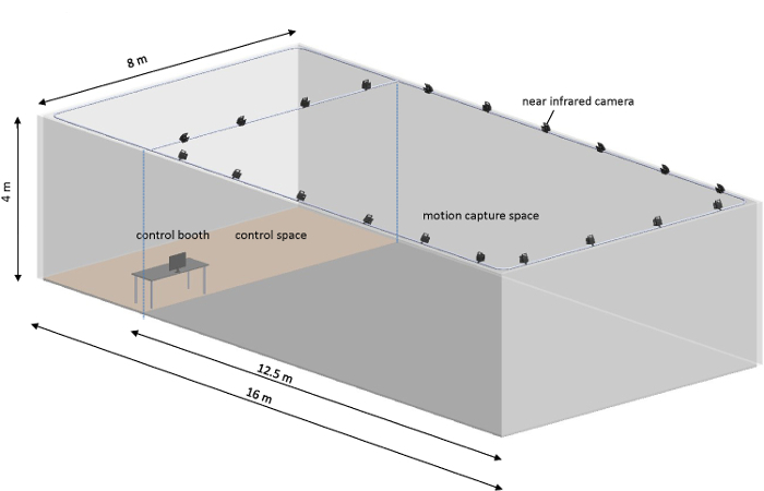 Figure 1: Free flight arena arrangement. The free flight arena was arranged into two parts: the control space (3.5 x 8 x 4 m3) was used for setting up the implantation kit (microscope and dissection tools) and control booth (computer, wireless base station, and camera controller), while the motion capture space (12.5 x 8 x 4 m3) was covered with 20 near-infrared cameras to record the position (X, Y, and Z) of the beetle. The flight arena was equipped with 30 lighting panels (60 x 60 cm2, 48 W) to make it as bright as daytime conditions during the experiment. Please click here to view a larger version of this figure.
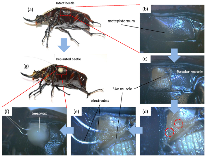 Figure 2: Procedure for electrode implantation. The beetle was anesthetized and immobilized with dental wax on a wooden block for the implantation procedure. (a-c) A small window was opened on the metepisternum of the beetle to access the 3Ax muscle. (d) Using an insect pin, two holes with a distance of 2 mm were pierced on the inner cuticle that bears the 3Ax muscle. (e) The electrodes were inserted into the muscles via these holes and kept in place with tweezers to ensure that no crosstalk occurred between the tips. (f-g) The electrodes were then fixed to the beetle using beeswax. Please click here to view a larger version of this figure.
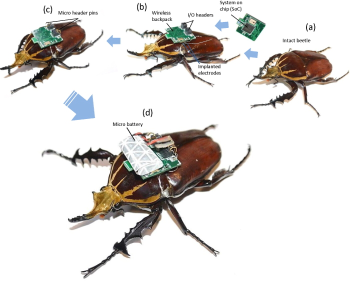 Figure 3:Procedure to produce an insect-machine hybrid system using an intact beetle. (a) The muscle of interest on a living beetle was implanted with a pair of silver wire electrodes. (b) After fixing the electrodes with beeswax, we mounted the backpack on the pronotum of the beetle using double-sided tape. (c) The free ends of the electrodes were inserted into the outputs of the backpack and secured with micropin headers. (d) A microbattery, which was covered with retro-reflective tape, was mounted on the backpack using double-sided tape and connected to the power pins of the backpack. Please click here to view a larger version of this figure.
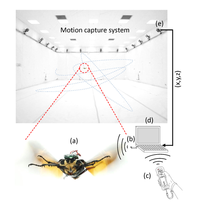 Figure 4:Wireless system for free flight experiment. The wireless system consists of (a) a cyborg beetle, (b) a wireless base station, (c) a remote, (d) an operating laptop with a Bluetooth receiver plugged in, and (e) a 3D motion capture system. When the user presses the command button on the remote, the custom flight control software on the laptop sends the stimulation command wirelessly to the cyborg beetle via a base station that is plugged into the laptop via a USB port. Once the backpack receives the command, it generates an electrical stimulus signal that stimulates the muscle. Simultaneously, the motion capture system records the 3D coordinates of the beetle and feeds them to the laptop for synchronization with the stimulation data. Please click here to view a larger version of this figure.
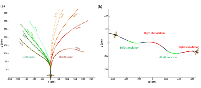 Figure 5:The behavior of the beetle owing to the electrical stimulation of the 3Ax muscle in free flight. (a) The beetle turned to the ipsilateral side when the left or right 3Ax muscle was stimulated, and the turning motion was graded as a function of the stimulation frequency. (b) The zigzag path of the flying beetle when the left or right 3Ax muscle was stimulated in sequence. The stimulus parameters were an amplitude of 3 V, a pulse width of 3 msec, and a frequency of 60-100 Hz. Please click here to view a larger version of this figure.
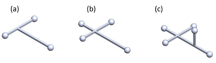 Figure 6:Proposed marker sets for tracking the 3D orientation (roll, pitch, and yaw) of the beetle. Configuration using (a) three markers, (b) four markers, and (c) five markers. Please click here to view a larger version of this figure.
Discussion
The implantation process is important, as it affects the reliability of the experiment. The electrodes should be inserted into the muscle at a depth of 3 mm or less depending on the size of the beetle (avoiding contact with nearby muscles). If the electrodes touch the nearby muscles, undesirable motor actions and behaviors may occur owing to the contraction of nearby muscles. The two electrodes should be well aligned to ensure that no short circuits occur. When melting and reflowing beeswax using a soldering iron, the experimentalist has to be careful and solder as quickly as possible, since the muscle can be burnt by prolonged contact with high temperatures, leading to a malfunction of the muscle. Although removing the cuticle is required to access the 3Ax muscle, the insertion and sealing process takes less than one minute and was managed to minimize damage to the muscle. The insects were returned to the rearing room after the experiments and could survive for up to 3 more months (end of their life time). To maintain good performance of the beetle, the beetle should be fed and allowed to rest for 3 to 4 hr after every 20 consecutive trials as the insect can become fatigued after many consecutive (40 to 50) flight trials and may not be able to open its wings.
As for the free flight experiment, volume calibration for the motion capture system is necessary, as it affects the trajectory tracking accuracy. It is important to fill the cameras' view full of the waves of the calibration wand with an image error of less than 0.3 for all of the cameras to maintain the accuracy of the motion tracking system. In addition, the surface of the marker should be clean, or the 3D motion capture system may frequently miss the marker. After calibration, a dummy test should be carried out by waving the battery wrapped with retro-reflective tape in the defined volume to check the coverage of the motion capture system. For testing the motion tracking accuracy, we measured the distance of two markers moving in the flight arena. The markers were fixed on a carton board with a distance of 200 mm to each other. The board was moved in the entire flight arena to obtain various positions of the two markers. The standard deviation was then calculated to be 1.3 mm (n = 3,000).
The free flight test facility (Figures 1 and 4) allows us to track the position (X, Y, and Z) of a flying insect along with a timestamp. Since only a single marker is attached to the beetle and the 3D motion capture system only detects that marker, the beetle is treated as a particle or a mass point. As such, data from the flying beetle has positional information but lacks orientation. Therefore, kinematic analysis from the positional data of the beetle provides only the translational velocity and acceleration along the X, Y, and Z axes without angular velocity or angular acceleration in rotations about the yaw, pitch, and roll axes. Multiple markers fixed on a beetle (such as the one shown in Figure 6) must be used for the 3D motion capture system to treat the flying insect as a rigid body and record rotation and translation data. However, the experimentalist must take note of the contribution of these markers to the kinetics of a flying beetle, because the marker is not a small piece of tape but needs to be large enough to be detected by the camera system with minimum tracking loss. Such an arrangement and the attachment of multiple markers may significantly increase its mass and moment of inertia25. Besides, the size of the flight arena can be set as large as possible within the coverage range of the motion tracking system to reduce the constraints to the free flight behavior of the beetle. For this paper, the size of the flight arena is defined based on the maximum coverage of motion capture system (12.5 x 8 x 4 m3).
Various possibilities exist to modifying this technique along with increasing the number of markers to record the orientation of the insect as mentioned above. The stimulation of different muscles in free flight can produce various behaviors, e.g., the basalar muscle for a contralateral turn7 and 3Ax muscle for an ipsilateral turn13. In addition, certain parts of the nervous system of an insect can induce various reactions. Optic lobe stimulation can induce flight initiation7, whereas the stimulation of antennae can induce contralateral turning in a walking insect12. Furthermore, we can change the function of the backpack from being an electrical stimulator to an electromyography recorder to record the activities of an insect during its natural behavior3,26.
The free flight stimulation of the beetle helped to reveal and confirm the natural function of the 3Ax muscle by enabling observations of the instantaneous reaction of the insect freely moving in air. Such information is not available under tethered conditions11,13,27-30. The behavior of an insect is constrained under tethered conditions and may be different from that in free flight, possibly leading to an incorrect understanding of insect behavior. Thus, free flight stimulation using this technique is a strong tool for validating the hypotheses drawn from tethered experiments. Furthermore, an insect-machine hybrid system is superior to current artificial flapping robots in terms of locomotive capabilities and power consumption13,17,31,32.
Insect-machine hybrid systems may replace artificial robots in the future as they inherit the complex and flexible structure and locomotive capabilities of a living insect and reduce the production time of the fabrication process. Various locomotive capabilities can help an insect-machine hybrid system to operate more efficiently in constrained spaces that involve the combination of walking and flying, e.g., in rescue missions. In addition, insect-machine hybrid systems can potentially be used as a tool for insect control in agriculture as it may be able to blend into natural insect colonies and help to control their activities.
Disclosures
The authors declare that there are no conflicts of interest.
Acknowledgments
This material is based on the works supported by Nanyang Assistant Professorship (NAP, M4080740), Agency for Science, Technology and Research (A*STAR) Public Sector Research Funding (PSF, M4070190), A*STAR-JST (The Japan Science and Technology Agency) joint grant (M4070198), and Singapore Ministry of Education (MOE2013-T2-2-049). The authors would like to thank Mr. Roger Tan Kay Chia, Prof. Low Kin Huat, Mr. Poon Kee Chun, Mr. Chew Hock See, Mr. Lam Kim Kheong and Dr. Mao Shixin at School of MAE for their support in setting up and maintaining the research facilities. The authors thank Prof. Michel Maharbiz (U.C. Berkeley) his advice and discussion, Prof. Kris Pister and his group (U.C. Berkeley) for their support in providing the GINA used in this study.
References
- Kutsch W, Schwarz G, Fischer H, Kautz H. Wireless Transmission of Muscle Potentials During Free Flight of a Locust. J. Exp. Biol. 1993;185(1):367–373. [Google Scholar]
- Fischer H, Kautz H, Kutsch W. A Radiotelemetric 2-Channel Unit for Transmission of Muscle Potentials During Free Flight of the Desert Locust, Schistocerca Gregaria. J. Neurosci. Methods. 1996;64(1):39–45. doi: 10.1016/0165-0270(95)00083-6. [DOI] [PubMed] [Google Scholar]
- Ando N, Shimoyama I, Kanzaki R. A Dual-Channel FM Transmitter for Acquisition of Flight Muscle Activities from the Freely Flying Hawkmoth, Agrius Convolvuli. J. Neurosci. Methods. 2002;115(2):181–187. doi: 10.1016/s0165-0270(02)00013-4. [DOI] [PubMed] [Google Scholar]
- Sanchez CJ, et al. Locomotion control of hybrid cockroach robots. J. R. Soc. Interface. 2015;12(105) doi: 10.1098/rsif.2014.1363. [DOI] [PMC free article] [PubMed] [Google Scholar]
- Sato H, et al. A cyborg beetle: insect flight control through an implantable, tetherless microsystem. IEEE 21st International Conference on Micro Electro Mechanical Systems; 2008. pp. 164–167. [Google Scholar]
- Bozkurt A, Gilmour RF, Lal A. Balloon-Assisted Flight of Radio-Controlled Insect Biobots. IEEE Trans. Biomed. Eng. 2009;56(9):2304–2307. doi: 10.1109/TBME.2009.2022551. [DOI] [PubMed] [Google Scholar]
- Sato H, et al. Remote Radio Control of Insect Flight. Front. Neurosci. 2009;3 doi: 10.3389/fnins.2010.00199. [DOI] [PMC free article] [PubMed] [Google Scholar]
- Daly DC, et al. A Pulsed UWB Receiver SoC for Insect Motion Control. IEEE J. Solid-State Circuits. 2010;45(1):153–166. [Google Scholar]
- Maharbiz MM, Sato H. Cyborg Beetles. Sci. Am. 2010;303(6):94–99. doi: 10.1038/scientificamerican1210-94. [DOI] [PubMed] [Google Scholar]
- Tsang WM, et al. Remote control of a cyborg moth using carbon nanotube-enhanced flexible neuroprosthetic probe. 2010 IEEE 23rd International Conference on Micro Electro Mechanical Systems (MEMS); 2010. pp. 39–42. [Google Scholar]
- Hinterwirth AJ, et al. Wireless Stimulation of Antennal Muscles in Freely Flying Hawkmoths Leads to Flight Path Changes. PloS ONE. 2012;7(12) doi: 10.1371/journal.pone.0052725. [DOI] [PMC free article] [PubMed] [Google Scholar]
- Whitmire E, Latif T, Bozkurt A. Kinect-based system for automated control of terrestrial insect biobots. Engineering in Medicine and Biology Society (EMBC), 2013 35th Annual International Conference of the IEEE; 2013. pp. 1470–1473. [DOI] [PubMed] [Google Scholar]
- Sato H, et al. Deciphering the Role of a Coleopteran Steering Muscle via Free Flight Stimulation. Curr. Biol. 2015;25(6):798–803. doi: 10.1016/j.cub.2015.01.051. [DOI] [PubMed] [Google Scholar]
- Erickson JC, Herrera M, Bustamante M, Shingiro A, Bowen T. Effective Stimulus Parameters for Directed Locomotion in Madagascar Hissing Cockroach Biobot. PLoS ONE. 2015;10(8):e0134348. doi: 10.1371/journal.pone.0134348. [DOI] [PMC free article] [PubMed] [Google Scholar]
- Zhaolin Y, et al. A preliminary study of motion control patterns for biorobotic spiders. Control & Automation (ICCA), 11th IEEE International Conference; 2014. pp. 128–132. [Google Scholar]
- Feng C, Chao Z, Hao Yu C, Sato H. Insect-machine hybrid robot: Insect walking control by sequential electrical stimulation of leg muscles. Robotics and Automation (ICRA), 2015 IEEE International Conference; 2015. pp. 4576–4582. [Google Scholar]
- Cao F, et al. A Biological Micro Actuator: Graded and Closed-Loop Control of Insect Leg Motion by Electrical Stimulation of Muscles. PLoS ONE. 2014;9(8):e105389. doi: 10.1371/journal.pone.0105389. [DOI] [PMC free article] [PubMed] [Google Scholar]
- Zhao H, et al. Neuromechanism Study of Insect-Machine Interface: Flight Control by Neural Electrical Stimulation. PLoS ONE. 2014;9(11):e113012. doi: 10.1371/journal.pone.0113012. [DOI] [PMC free article] [PubMed] [Google Scholar]
- Tsang WM, et al. Flexible Split-Ring Electrode for Insect Flight Biasing Using Multisite Neural Stimulation. IEEE Trans. Biomed. Eng. 2010;57(7):1757–1764. doi: 10.1109/TBME.2010.2041778. [DOI] [PubMed] [Google Scholar]
- Barron AB. Anaesthetising Drosophila for behavioural studies. J. Insect Physiol. 2000;46(4):439–442. doi: 10.1016/s0022-1910(99)00129-8. [DOI] [PubMed] [Google Scholar]
- Cooper JE. Anesthesia, Analgesia, and Euthanasia of Invertebrates. ILAR Journal. 2011;52(2):196–204. doi: 10.1093/ilar.52.2.196. [DOI] [PubMed] [Google Scholar]
- Miller TA. Insect neurophysiological techniques. Springer Science & Business Media; 2012. [Google Scholar]
- Leary S, et al. AVMA guidelines for the euthanasia of animals. 2013.
- Heath B, West G, Heard D, Caulkett N. in Zoo Animal and Wildlife Immobilization and Anesthesia. Blackwell Publishing Ltd; 2008. Mobile Inhalant Anesthesia Techniques; pp. 75–80. [Google Scholar]
- Mischiati M, et al. Internal models direct dragonfly interception steering. Nature. 2015;517(7534):333–338. doi: 10.1038/nature14045. [DOI] [PubMed] [Google Scholar]
- Kutsch W, Berger S, Kautz H. Turning Manoeuvres in Free-Flying Locusts: Two-Channel Radio-Telemetric Transmission of Muscle Activity. J. Exp. Zoolog. Part A Comp. Exp. Biol. 2003;299(2):139–150. doi: 10.1002/jez.a.10297. [DOI] [PubMed] [Google Scholar]
- Wang H, Ando N, Kanzaki R. Active Control of Free Flight Manoeuvres in a Hawkmoth, Agrius Convolvuli. J. Exp. Biol. 2008;211(3):423–432. doi: 10.1242/jeb.011791. [DOI] [PubMed] [Google Scholar]
- Sato H, Maharbiz MM. Recent developments in the remote radio control of insect flight. Front. Neurosci. 2010;4 doi: 10.3389/fnins.2010.00199. [DOI] [PMC free article] [PubMed] [Google Scholar]
- Tien Van T, et al. Flight behavior of the rhinoceros beetle Trypoxylus dichotomus during electrical nerve stimulation. Bioinsp. Biomim. 2012;7(3):036021. doi: 10.1088/1748-3182/7/3/036021. [DOI] [PubMed] [Google Scholar]
- Sane SP, Dickinson MH. The control of flight force by a flapping wing: lift and drag production. J. Exp. Biol. 2001;204(15):2607–2626. doi: 10.1242/jeb.204.15.2607. [DOI] [PubMed] [Google Scholar]
- de Croon GC, et al. Design, aerodynamics and autonomy of the DelFly. Bioinsp. Biomim. 2012;7(2):025003. doi: 10.1088/1748-3182/7/2/025003. [DOI] [PubMed] [Google Scholar]
- Ma KY, Chirarattananon P, Fuller SB, Wood RJ. Controlled Flight of a Biologically Inspired, Insect-Scale Robot. Science. 2013;340(6132):603–607. doi: 10.1126/science.1231806. [DOI] [PubMed] [Google Scholar]