Abstract
This paper presents several mechanical models of a high-strength cable-driven dexterous manipulator designed for surgical procedures. A stiffness model is presented that distinguishes between contributions from the cables and the backbone. A physics-based model incorporating cable friction is developed and its predictions are compared with experimental data. The data show that under high tension and high curvature, the shape of the manipulator deviates significantly from a circular arc. However, simple parametric models can fit the shape with good accuracy. The motivating application for this study is to develop a model so that shape can be predicted using easily measured quantities such as tension, so that real-time navigation may be performed, especially in minimally-invasive surgical procedures, while reducing the need for hazardous imaging methods such as fluoroscopy.
Index Terms: Cable-driven robots, kinematics, medical robots and systems, snake-like robots, underactuated robots
I. Introduction
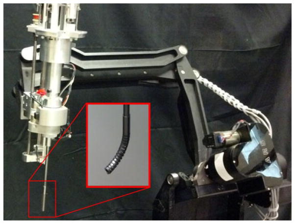
Small, dexterous manipulators are becoming increasingly popular for minimally-invasive surgical procedures [1]–[7]. This paper is about a new type of high-strength cable-driven flexible manipulator for medical applications [8]–[10]. This is a small snake-like device that can be hand held, or mounted to a larger robot for positioning (see Fig. 1). The manipulator is designed with a large open lumen expressly for the procedure of removing diseased bone during hip revision surgeries, without necessitating removal of a well-fixed acetabular implant [8], although it is well suited for other types of minimally-invasive surgical interventions. Visualizing the shape of the manipulator while it is inside the body is thus an important goal. In addition, a good understanding of the relation between design variables and manipulator performance metrics (for example, the effect of cable strength on manipulator stiffness) is important for designing new and improved systems.
Fig. 1.
High strength dexterous manipulator with large open lumen [8] mounted on a LARS surgical robot. The LARS is a 7-DOF robot designed to assist in surgical procedures [12].
Many existing cable-driven manipulators are described well by constant curvature models [11]. While the constant curvature assumption describes our manipulator with good accuracy at small deflections, the constant curvature prediction does not match the observed shape of our robot at higher cable tensions and deflections. One of the main advantages of our new design is that it is expressly intended for operation at high forces and deflections, so it is important to develop a predictive model that describes the manipulator behavior in these regimes of operation.
The purpose of this paper is to investigate the interaction between the actuating cables and their guide channels, in order to determine the extent to which this interaction is responsible for deviation from the “ideal” constant curvature model. Further, we take a step toward developing a model which predicts the shape of the manipulator given only material properties and the time-dependent tension on the drive cables. While specifically driven by our own particular manipulator design, this study can be applied to a broad range of cable-actuated flexible manipulators.
Friction between cable and manipulator plays an important role in manipulator behavior. While friction and stiffness effects have been relatively well-studied in the context of cable-driven robotic hands [13]–[16], friction is not considered in many works on cable-driven continuum manipulators, both pioneering and recent [17]–[20]. A number of studies investigate the frictional interaction between a snake-like medical device and the surrounding tissue, e.g., [21], but few studies explicitly address the friction of internal actuation cables. Some recent exceptions are [22]–[25]. In [22], cable friction is studied in depth, and shown to be at the root of hysteretic behavior shown in cable-driven surgical tools. A detailed lumped-parameter model using Dahl friction is presented in [23] and [24], which accurately predicts the curvature and tip location, after bending, of a manipulator constructed with a Teflon backbone and Teflon-coated cables. In this paper, we use a similar dynamic model with standard Coulomb friction to accurately predict the curvature and tip location, after bending, of a manipulator made with a Nitinol backbone and stainless steel cables. Extending beyond [23], [24], we present a geometric analysis of the free motion of the cable within the channels, a discussion of the separate roles of cable and backbone elasticity in manipulator stiffness, and we report experimental data on the effect of cable friction on time-dependent manipulator shape.
In Section II, basic kinematic and quasi-static dynamic model is presented. This section addresses the kinematic relation between cable length and manipulator shape, including motion of the cable within the guide channel. Section III builds on the kinematic model from Section II to investigate how manipulator shape and stiffness is affected by cable tension and material properties. Section IV addresses the problem of parameterizing the nonconstant curvature manipulator shape, as well as effects of friction between cable and guide channel on the manipulator’s shape and time-dependent behavior.
II. Kinematics of the Manipulator and Cables
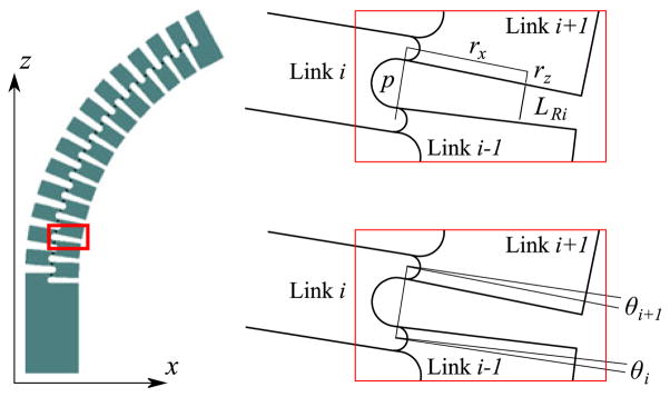
This section presents a basic kinematic model of the manipulator and the drive cables (see Fig. 2).
Fig. 2.
Geometry for determining cable length. Link 0 is the base, and link numbering proceeds sequentially up the manipulator. The links shown in the inset are links 3, 4 and 5 (i = 4). Positive values of θ correspond to the configuration shown.
A. Backbone Kinematics
The manipulator is designed to be used with a supporting robot (see Fig. 1) that actuates the base platform. For this reason, only the flexible backbone portion of the manipulator is considered in the kinematic model. The manipulator is made of two nested tubes with alternating slots cut in the sides. There are fourteen slots on each side of the tube, resulting in 27 flexure joints. Because of the symmetrical construction and small deflection of the flexure joints, the joints are well described by a simple kinematic revolute joint equipped with a torsional spring (see Section III-D for additional discussion). At each revolute joint, the stiffness of the flexure is represented by a nonlinear spring. Joint i connects rigid links i and i − 1. The base link (link 0) is fixed. The forward kinematics, written in product of exponentials form, are
where gst is the current configuration of the end-effector, θ is a 27 × 1 vector of joint angles, and gst0 is the initial end-effector configuration. See the Appendix for a brief review of this notation, and [26] for detailed coverage. The initial configuration of each link is given by the 4 × 4 matrix representation
where qi = (0, 0, (i − 1)p)T. The base link is link 0; links 1 through 26 are the repeated subunits of the compliant backbone; and the end-effector is link 27, that is, gst = gs27. The spacing between links is p = 1.21 mm. The configuration of the ith link is obtained by
The axis of rotation of each joint is in the direction of ωi = (0, 1, 0)T. The joint twists are given by
The manipulator Jacobian relates joint velocities to the spatial velocity of the end-effector
| (1) |
is a 6 × 27 matrix. For a general redundant manipulator, can have rank of at most 6. However, since all of the joints in this manipulator are parallel, in fact has rank of at most 3, corresponding to the three degrees of freedom with which the end-effector can move in the plane. For most configurations gst there are many corresponding θ. The set of θ corresponding to a given configuration is called the self-motion manifold. The manipulator can move freely among these θ, given that the infinitesimal motions satisfy . With the end-effector of the manipulator held fixed, the internal spring torque at the joints moves the manipulator along the self-motion manifold to a configuration of minimum energy.
B. Cable Kinematics
The manipulator is actuated by two cables, one threaded through each side. The length of each cable can be treated as a kinematic configuration variable, and the same technique of forward kinematics and Jacobians can be applied to gain useful insight into the functioning of the manipulator.
Referring to Fig. 2, consider LRi, the length of the right cable, in between link i − 1 and i + 1. The length of this cable segment is the length of the vector between cable entrance points in link i − 1 and link i + 1. For consistency with the rest of the discussion the cable is represented as a line segment in three dimensions, written as a vector in ℝ3, even though the manipulator is assumed to lie in the xz plane. Writing this vector relative to a frame fixed on link i, the length of the cable segment is
where ci = cos(θi) and si = sin(θi).
Each joint angle has limited range of motion (approx. 0.14 rad) so it is reasonable to make the assumptions that ci = 1 and si = θi. This simplifies the aforementioned to
The fact that rz ≪ rx and rz ≪ p (rz = 0.2 mm, p = 1.21 mm, rx = 2.5 mm) allows us to neglect the term, and LRi further simplifies to
where LRSi is the approximated length of the cable segment under the aforementioned simplifying assumptions, and LRS is likewise the approximated length of the entire cable. The total length of the right cable is then given by
The length of the right cable for a given set of joint angles is
| (2) |
The same procedure gives the length of the left cable
| (3) |
where LR0 and LL0 are constant terms containing the length of the cable offset (external to the flexible portion of the manipulator) and a sum of other dimensions. LR0 = LRoffset+ 27p − 2rz, and LL0 = LLoffset + 27p − 2rz. For convenience we write the vector of cable length as L(θ) = (LR(θ), LL (θ))T.
C. Cable Coupling Matrix
The coupling matrix [26] P(θ) relates joint velocities θ̇ to change in cable length
| (4) |
where
In general the coupling matrix may depend on θ. However, using the simplified expressions for cable length (2), (3) results in
| (5) |
This simplified coupling matrix accurately describes many cable-driven manipulators with a flexible backbone. While the structure of PT is trivial, it provides helpful insight into the manipulator. Starting at an initial θ0, any motion θ̇ in the right nullspace of PT will leave the cable lengths unchanged. By inspection, rank(PT) = 1, so there is a 27 − 1 = 26 dimensional subspace of motions in θ for which cable lengths will remain constant. By inspection of the manipulator kinematics, we see that the sum of the joint angles is in fact the angular orientation of the end-effector. The cable self-motion manifold is therefore any motion for which the orientation of the end-effector remains constant.
D. Comparison of Cable Length Models
In the physical manipulator, the actuating cables are free to move sideways in the guide channels, and the manipulator shape becomes bistable at high counter-tensions. A high-accuracy model of cable length for this manipulator was presented in [9]. This model uses Dijkstra’s algorithm to find the shortest route by which a cable of nonzero thickness can pass through a channel. In this section, we compare the simple cable length model to the higher accuracy one of [9].
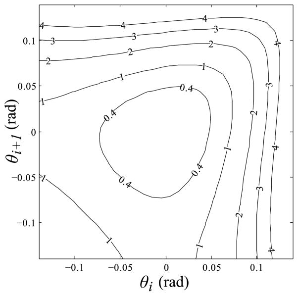
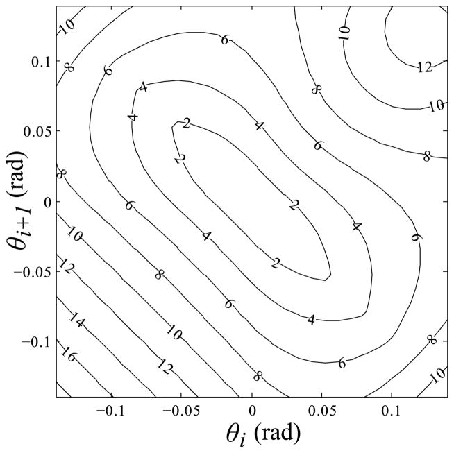
The ideal “zero channel width” length LRi represents the length of an ideal zero-thickness cable through a zero-thickness channel. This quantity is an upper bound to the length of a cable segment that is free to move in a wider channel, since widening the channel will only increase the number of possible shorter paths. The error between LRi and the simplified LRSi is shown in Fig. 3.
Fig. 3.
Contour map of the error between the ideal “zero channel width” length of one cable segment LRi, and the approximate length LRSi, where error = LRi − p + (θi + θi+1)rx + 2rz. The error is less than five micrometers over nearly the entire range of operation (nominal segment length is 810 micrometers). Contour units are micrometers.
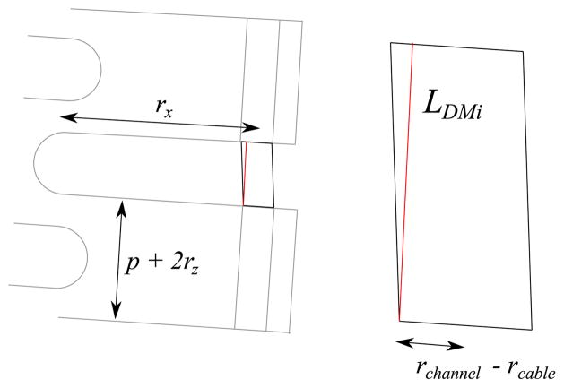
The shortest possible length of an intersegment cable length LDMi can be found as illustrated in Fig. 4. A lower bound on the total length of a cable free to move in a larger channel LDM is found by summing the minimum possible lengths of all segments, LDM = Σi LDMi. Fig. 5 shows the maximum error between the simple cable model (LRSi) with the upper (LRi) and lower (LDMi) bounds of the cable lengths predicted by the method of [9].
Fig. 4.
Lower bound on the length of a cable that is free to move within a channel can be found by summing the minimum possible length of individual segments. LDMi is the minimum possible length of a cable segment between two sections. The minimum length of a cable segment within a manipulator section is simply p + 2rz. A cable segment can move sideways within a channel by a distance of ±(rchannel − rcable).
Fig. 5.
Contour map of the worst case error between the simple length model and upper and lower bounds of the high-accuracy length model reported in [9]. The plot shows max(||LRSi − LRi)||, ||LRSi − LDMi||). Contour units are micrometers.
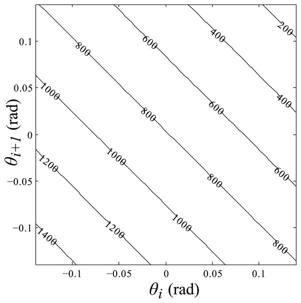
The error between the ideal “zero channel width” length LRi, and the simple approximated length LRSi is very small—on the order of micrometers across the whole operating range (see Fig. 3). The error between LRSi and the bounds of method [9] is somewhat higher (see Fig. 5), but in both cases the error is small compared to the total length of the cable (see Fig. 6). In many cases, this small error can be neglected and the simple length model can be used. However, at inflection points, that is, places along the manipulator where the joint angles θi change sign, it is important to consider these very small changes in cable length. Cases where joint angles change sign occur if there is an “S-bend” shape in the manipulator, and they also occur even when the manipulator is in the shape of a single circular arc, bending from one side to the other [9]. As the manipulator straightens, the most stable shape becomes a slightly buckled “S-bend” rather than a perfectly straight line. While these shape changes are rather small, they are accompanied by very rapid accelerations as the taught cable snaps from one side of a channel to another. Predicting and understanding these bifurcations of equilibrium state are important for a complete picture of manipulator behavior, but this topic is left for future work. The error analysis provides confidence that the conclusions we draw using the simplified length model and coupling matrix will closely approximate the true behavior of the physical manipulator in regions where bifurcations do not occur.
Fig. 6.
Contour map of intersegment cable length using the simplified expression LRSi = p − (θi + θi+1)rx −2rz. Compare these values to the errors shown in Figs. 3 and 5. Contour units are micrometers.
III. Quasi-Static Dynamic Model, Cable Tension, and Manipulator Stiffness
Equipped with the manipulator and cable Jacobians, we are now ready to address how the manipulator, in the absence of cable friction, responds to cable tension and to forces applied to the end-effector. While there are sophisticated methods for solving the equilibrium configurations of elastic chains (e.g., [27]), we take a more basic approach. Recall the familiar robot dynamics [26]
Several simplifying assumptions are made to reduce this general equation of motion to a set of decoupled first order differential systems. We are primarily interested in the equilibrium configuration, so we assume the movement of the manipulator is slow. Hence, the contributions of the Coriolis terms are negligible, and the joints are decoupled, i.e., C(θ, θ̇)θ̇ ≈ 0 and M is diagonal. The constitutive behavior of the flexible links is modeled as a nonlinear spring in parallel with a viscous damper. These terms appear in N, i.e. N(θ, θ̇) = Kθ (θ)θ + Bθ̇. These same assumptions are used successfully to model continuum manipulators in [23], [24].
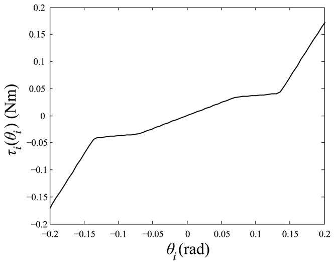
The matrix Kθ (θ) represents the elasticity of the flexures in addition to the obstruction to movement caused by collisions between joint segments. Referring to Fig. 2, note that the presence of a collision between link i − 1 and i + 1is determined by both θi and θi+1. Precise conditions for collisions are cumbersome to calculate, but a simplifying assumption is to limit each θi to a value such that collisions are guaranteed not to occur. The flexure elasticity and intersegment collisions are modeled using a dual rate torsional spring for each joint, Kθ (θ) = diag(ki(θi)) where
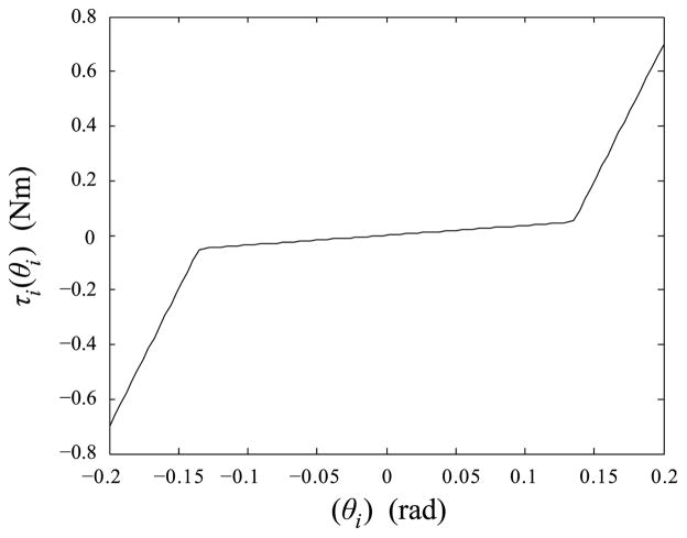
The corresponding joint torque induced by this nonlinear spring constant, τi(θi) = ki(θi)θi, is shown in Fig. 7.
Fig. 7.
Nonlinear dual rate spring used to model flexure elasticity and intersegment collisions. k1 = 0.36 Nm/rad, k2 = 10 Nm/rad, θthresh = 0.135 rad.
The aforementioned assumptions result in a system of n decoupled second order equations
which can be further reduced to a first order system by assuming that damping is dominant in the dynamic behavior
| (6) |
While this is not an accurate assumption to make for modeling high-speed transient behavior of the manipulator, it is entirely reasonable in this case because the primary quantity of interest is the equilibrium system configuration.
The torque induced on the joints τind is due to the combined effects of the applied wrench at the end effector and tension on the cables. Recall that the transpose of relates a general spatial wrench, Fs, to the induced torques on the joints of the robot
| (7) |
The dimensions of are 27 × 6. Wrenches in the right nullspace of , i.e., Fs such that correspond to wrenches that are supported entirely by the structure of the manipulator, independent of joint torques. Because of the planar design of the manipulator, is of rank at most 3. Basis vectors for the right nullspace (written in body coordinates) are F1 = (0, 1, 0, 0, 0, 0)T, F2 = (0, 0, 0, 1, 0, 0)T, and F3 = (0, 0, 0, 0, 0, 1)T. That is, τwrench = 0 for any
| (8) |
The adjoint transformation Adg is reviewed in the Appendix. In special configurations can drop rank to less than 3, such as when θi = 0 for i = 0…26. In this case, the rank of is 2 and the additional basis vector is F4 = (0, 0, 1, 0, 0, 0)T.
In a manner similar to (7), the coupling matrix relates cable tension to the induced joint torques [26]
| (9) |
where T = (TR, TL)T is the vector of cable tensions, with TL and TR being the left and right cable tensions, respectively. It is assumed TL, TR ≥ 0.
One further point regarding (9) should be mentioned. Inspection of (5) shows that cable tension results in the same torque being uniformly induced on all joints. In the next section, it is shown that this is consistent with the familiar constant-curvature assumption that is often used to model continuum manipulators.
The full quasi-static equations of motion are given by incorporating the induced torques (7) and (9) into the simplified dynamics model (6) and setting the applied joint torque τ to zero
This equation can be solved iteratively for the joint angles θ(t) by integrating
| (10) |
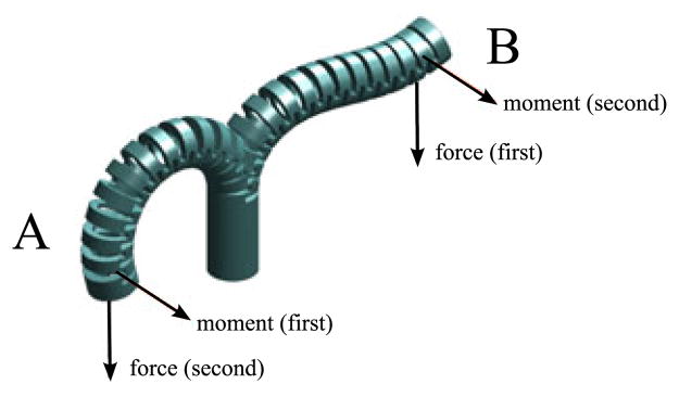
from an initial θ(t0). This results in the equilibrium shape of the manipulator given a time-dependent application of end-effector loading and cable tensions. One example is shown in Fig. 8. The manipulator starts from θ = 0and then a force and moment load are applied. Different equilibrium solutions are reached depending on the order of application of force and moment, even though the final loading conditions are the same. Note that applying a pure moment to the end-effector, i.e. Fs = a(0, 0, 0, 0, 1, 0)T is exactly equivalent to applying cable tension, TL − TR ≠ 0. In each case torques are induced uniformly over all joints. For this reason, the example shown in Fig. 8 is also valid if a cable tension were applied instead of a moment to the end-effector.
Fig. 8.
Path-dependent solutions to the quasi-static dynamic model. In solution A, the moment is applied first, followed by the force. In solution B, the force is applied first and the moment second.
A. Constant-Curvature Regime
In the absence of external load, i.e., when Fs = 0, the equilibrium configuration is
| (11) |
Using the simplified coupling matrix generated with small angle approximations (5), and assuming the joints are in their linear regime, i.e. ki(θi) = k1, the equilibrium configuration is
Every joint angle is the same, so the joint axes are located along the arc of a circle with radius R = p/θi. Thus, the model is consistent with a constant curvature approximation, and the curvature is given by
| (12) |
B. Cable Length as Control Inputs
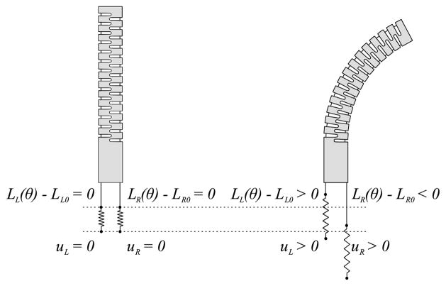
The equations of motion in (10) use cable tension T as a control input. In some cases it is convenient to consider the length of the cables as the control input instead. Let u(t) = (uR(t), uL(t))T be the controlled positions of the ends of the cables. Cable elasticity is modeled as a single spring element (external to the manipulator) in series with an ideal inelastic cable (see Fig. 9). Elongation of the cables, defined as the difference between the actual and the unstretched lengths, is given by
Fig. 9.
Each cable is modeled as an inelastic ideal cable in series with a spring. The position of the spring ends, uL and uR, are the control inputs.
| (13) |
where d = (dR, dL)T and L0 = (LR0, LL0)T. In general, the cable tension is some function of the elongation
| (14) |
The expressions for T and d can be substituted directly into (10) for the equations of motion using cable lengths as the control input. It is assumed that u is chosen such that dR, dL, TR, TL ≥ 0.
In the upcoming discussion on stiffness, it is necessary to find the change in cable tension in response to a small perturbation in the manipulator shape. This can be done by linearizing the tension about some operating point d0 = L(θ0) − L0 + u0. Noting that for a fixed control input u0, an infinitesimal displacement in joint angles δθ results in an elongation of δd = PT (θ0)δθ, the linearized tension is
| (15) |
where the partial derivatives are evaluated at θ0, u0. When the cables are modeled as linear springs, this expression simplifies to
| (16) |
where Kc = diag(kc) is the tensile spring constant of the cables. A simple approximation for cable spring constant is
where E is Young’s modulus and A is the cable cross-sectional area. Approximate values for the stainless steel cables used in this manipulator are E = 1.8 × 10¹¹ N/m2, A = 5.1 × 10⁻⁸ m2, L0 = 2.2 × 10⁻¹ m, resulting in kc = 4.1 × 10⁴ N/m.
C. Manipulator Stiffness
Once the manipulator attains an equilibrium configuration, it will to some degree maintain that configuration in response to disturbances from the environment. This behavior can be modeled as a general stiffness matrix. Because a high stiffness is desirable, it is useful to consider the contributions of various design parameters to this stiffness. In this section, we address the effects that various design parameters have on manipulator stiffness.
1) Km—Jointspace Stiffness
Assume that we start with an unloaded manipulator and then move the cables to some location specified by u0. The manipulator will attain an equilibrium configuration θ0. We assume that θ0 places the backbone flexures in their linear regime, i.e. Kθ (θ0) = Kθ = diag(k1). Holding u0 constant, suppose the backbone is displaced by an infinitesimal virtual motion δθ. The resultant torque appearing on the flexure joints is due to deformation of both the backbone and the cables. This torque is given by
| (17) |
It is a reasonable assumption that P(θ0 + δθ) = P(θ0) = P, as it was shown in Section II-C that a constant P matrix is a very close approximation of the true P(θ). Expanding (17) and making use of (16) we have
Note from (11) that Kθ θ0 = −P(θ0)T(θ0, u0), so we have now
The quantity Km is a 27 × 27 symmetric positive definite matrix representing the combined stiffness of the backbone and cables, in jointspace coordinates. The matrix PKcPT is equal to a constant times the matrix of ones, that is, every element is equal to . Further, PKcPT has rank one, and the eigenvector corresponding to its only nonzero eigenvalue is (1, 1, 1, …, 1)T.
2) Kw—Workspace Stiffness
We define workspace stiffness as a natural extension to a linear spring, except for full 3-D motion, as described in [15], [16], [28]
where Fs is a six-element wrench applied to the end-effector, δt is an infinitesimal timestep, is an infinitesimal displacement of the end-effector, composed of a small rotation about an arbitrary axis and small translations along three orthogonal axes. Ks is a 6 × 6 stiffness matrix.
For the purposes of this discussion, only the “flexible” degrees of freedom are considered in the stiffness analysis. The manipulator is assumed to be effectively rigid in response to forces of the form in (8). Stiffness resisting forces in the directions of F1, F2, F3 will not be considered, as the stiffness in these is much higher than that in the intentionally flexible modes. With this assumption, parameterizing the end effector configuration as X = (x, z, ϕ)T, the Jacobian mapping between these coordinates and the joint velocities is
| (18) |
where JX is a 3 × 27 matrix. Note that the Jacobian JX is neither the spatial nor body manipulator Jacobian [see (27)]. The distinction between these three types of Jacobian mappings is described in detail in [26]. The kth entry of Jx is
| (19) |
The kth entry of Jz is
| (20) |
where p is the spacing between links (see Section II-A), and the kth entry of Jϕ is simply equal to 1, i.e. Jϕk = 1.
Assume that we start with an unloaded manipulator and then move the cables to some location specified by u0. The manipulator will attain an equilibrium configuration θ0. We assume that rank JX (θ0) = 3 and that θ0 places the backbone flexures in their linear regime, i.e. Kθ (θ0) = Kθ = diag(k1). We are interested in determining the 3 × 3 stiffness matrix Kw that describes the reactive force of the end-effector in response to infinitesimal disturbances in position
Holding u0 constant, suppose the end-effector is displaced by an infinitesimal motion δX. In jointspace coordinates, this deflection by δX corresponds to an infinitesimal motion δθ away from the equilibrium joint angles θ0. We can solve for δθ by minimizing the potential energy of the mechanical system, subject to the constraint δX = JX (θ0)δθ. Taking the zero point of the potential energy to be the value at equilibrium (i.e., θ = θ0) the potential energy is given by
| (21) |
The constrained minimization problem can then be formulated as a linear system of equations using the method of Lagrange multipliers
| (22) |
where λ is a 3 × 1 vector of Lagrange multipliers. Provided that the three rows of JX are linearly independent, the matrix of constraint equations can be inverted as
where
| (23) |
With the inverted matrix, we may solve (22) for δθ
| (24) |
Substituting (24) into (21) verifies that the potential energy as a function of δX is
| (25) |
and the reactive force at the end effector is therefore
| (26) |
3) Stiffness Discussion
The structures of Km and Kw provide us with useful insight into manipulator stiffness. When cable elasticity is linear, the stiffness does not depend on cable tension. This runs somewhat counter to our intuition, because we are familiar that tensioning both the agonist and antagonist cables usually results in a stiffening of the manipulator (a person can demonstrate this with their own limbs). However, it is known that this stiffening effect of cable counter-tension is in fact due to the cables themselves exhibiting a nonlinear spring constant [29], [30].
When cable stiffness is nonlinear, the manipulator stiffness can be controlled, to some extent, by changing the elongation of the cables. For example, if cable stiffness is proportional to the square of the elongation, , then the cable stiffness matrix depends linearly on d, Kc = diag(kcdR, kcdL). A change in Kc will therefore influence Km and Kw. However, the effect is limited by the span of PKcPT. Motions in jointspace that lie within the nullspace of PKcPT are not affected by the cables at all. The consequence of this is that there is a two-dimensional subspace of motions in the workspace (corresponding in this case to translations in x and z that leave ϕ unchanged) for which stiffness is independent of Kc and determined only by Kθ. The addition of more actuation cables to the manipulator increases the rank of P and allows stiffness control in additional degrees of freedom. For example, additional pairs of cables can be attached to adjacent pairs of segments, evenly spaced along the length of the manipulator. This is essentially the same as concatenating multiple two-cable-actuated manipulators together end-to-end.
An intuitive counting argument illustrates how many cables are needed to control joint angles as well as stiffness. As derived in [31] and clearly summarized in [32], a n × n stiffness matrix K is determined by n(n + 1)/2 parameters. If n joint torques must also be controlled, then to fully control the joint angles and full stiffness matrix, a minimum of n(n + 3)/2 cables are required. Thus, at least nine cables are needed to fully control (x, z, ϕ) and Kw. As pointed out in [32] it is common to neglect off-diagonal terms in Kw, which results in a requirement of 2n cables. Assuming we are concerned only with the diagonal terms of the stiffness matrix, at least six cables would be needed to control all three degrees of freedom (x, z, ϕ) and their corresponding stiffnesses (kxx, kzz, kϕϕ). Since the manipulator only has two cables, it is clear that at most two of these six quantities are controllable. The two variables that are fully controllable are the angle of the tip ϕ and the corresponding stiffness kϕϕ.
D. Validity of Modeling Flexures as Revolute Joints
It is common to model flexure joints in a segmented continuum manipulator as kinematic revolute joints (e.g., [10], [23], [24], [33], [34]), however in certain circumstances it is necessary to model additional degrees of freedom in the system. For example, in [19] the axial compression of a continuum manipulator is modeled in addition to the bending mode of deformation. In some applications, individual flexures may need to be modeled as more than one kinematic joint. For example, a planar parallel manipulator described in [35] required three of its nine flexure joints to be modeled as a combination of revolute and prismatic joints. In order to support our assertion that the flexure joints in our manipulator are accurately modeled as revolute joints, a segment of the manipulator was studied using finite element analysis (FEA) in Solidworks (see Fig. 10). Representative material parameters for Nitinol were chosen (E = 60GPa, ν = 0.3) and typical loads were applied. The case of axial compression results in negligible deformation (maximum 0.015 mm). When compared with a segmented model made of rigid links connected by revolute joints, deformation due to a pure moment applied at the tip is consistent with constant joint angles, θ1…4 = 0.129 rad, while that due to a transverse load at the tip is consistent with uniformly decreasing joint angles, θ1…4 = (0.096, 0.074, 0.053, 0.032) rad. All three cases produce results consistent with our model, indicating that no additional degrees of freedom need to be incorporated.
Fig. 10.
FEA results for deformation of a manipulator segment in response to different applied loads. Color scale indicates magnitude of displacement. Left: 10 N axial compression, deformation scale = 100. Center 0.1 Nm moment, deformation scale = 1. Right: 10 N transverse load, deformation scale = 1.
In addition to validating the kinematic assumptions, the same FEA results can be used to estimate an equivalent torsional stiffness for the flexure joints. Simple statics is used to determine the torque induced at each joint given the loading conditions. Joint stiffness is then estimated as the ratio of torque to angle. Values derived from the FEA results are compared with values derived from experimental measurements in Table I. The “cable-driven bending” experiments and the method for determining the associated stiffness are described in Section IV-B4. In the case of the “0.2-N transverse load” experiment, a transverse load was applied to the tip of an isolated manipulator backbone without cables, the tip deflection was measured using calibrated image processing, and then the model of (10) was used to find a value of k1 such that the model tip deflection matched the observed. The discrepancy between the two experimental cases may be due in part to differences in dimension and material properties between the two different manipulator backbones used in the test. The discrepancy between FEA results and between FEA and experiment may be due in part to inaccurate material properties and excessive deformations. Improving the accuracy of these estimates is a topic for future work.
TABLE I.
Estimated Joint Stiffness Values
| Configuration | k1 (Nm/rad) |
|---|---|
| Experiment, 0.2-N transverse load | 0.36 |
| Experiment, cable-driven bending | 0.48 |
| FEA, 10-N transverse load | 0.57 |
| FEA, 0.1-Nm moment | 0.77 |
IV. Modeling Shape at High Strain and Nonnegligible Cable Friction
The model presented in Section III works well for small loads and deflections, but it is not accurate at higher deflections. This section includes cable friction in a model that more accurately predicts behavior at high deflections. The problem can be divided into two parts. First, we want to find a way to represent the shape of the manipulator with a small number of parameters. Second, we want to relate the shape parameters to quantities that are easy to measure, namely cable length and cable tension.
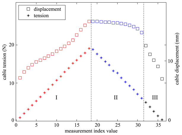
A representative dataset underlying the construction of this model is shown in Fig. 11. For this experiment, a light counter-tension was maintained on the right cable, while tension on the left cable was gradually increased and then decreased. An automated actuation system (for additional details see [8]) was used to control the manipulator during the test. The manipulator was moved slowly between sample points, and at rest when the sample data were taken. The typical time between sample points was about five seconds. At each sample point an image of the manipulator was also recorded. The cable tension was recorded with load cells (Honeywell 060-1426-04) that have an accuracy of ±0.11N. The cable displacement was controlled with a linear actuator (Haydon Kerk 35H4A-12) with a resolution of 0.0079mm per motion step.
Fig. 11.
Cable tension and displacement during bending and unbending of the manipulator. A constant counter-tension of 0.45 N is applied to the opposite cable. There are three regimes of operation (I–III).
The data from eight different experiments are uploaded as supplemental material to this paper. Fig. 11 shows results of one such test. Tension and displacement for the left cable is plotted for each sample point. Fig. 12 shows one example configuration during the test. This image shows the manipulator from underneath, so the “left” cable is actually on the right side of the image, and the corresponding angles θj for the configuration shown are negative.
Fig. 12.
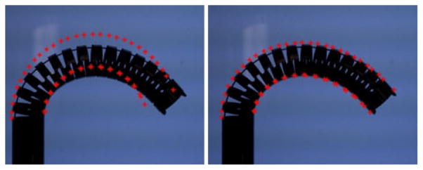
Image of the actual manipulator bending under high cable tension. Left: Virtual notch points (Q̃i) for the best fit constant curvature fitting (θj = cons) are shown overlaid in red dots. Right: (Q̃i) using the fitting θj = a + bj.
There are three regimes of bending during the experiment. In regime I the cable is tightening, and the manipulator bends in a predictable manner. This corresponds to a roughly linear increase in cable displacement (although the slope will increase as notches begin to close at high deflections, and there can be a small discontinuity if the manipulator passes through θ = 0). In regime II, the tension in the left cable is decreasing, but the cable length is remaining close to constant and the overall shape of the manipulator is not changing dramatically. There is a sudden transition from regime II to III, when the cable to starts to move a substantial amount and the manipulator returns to its equilibrium shape. This behavior is repeatable over many tests and follows a similar pattern for different values of counter-tension, as can be seen by viewing the supplemental information.
A. Parameterizing Manipulator Shape
Each image taken during a test is processed by manually digitizing the location of corner points on the notches of the manipulator body. The location of these “notch points” is used as a baseline ground truth for the shape of the manipulator. The maximum error in point location using the manual digitization process is 0.15 mm [10]. Fifty-eight notch points (Qi) are selected, numbered sequentially from the lower left, as seen in Fig. 12, and proceeding anticlockwise around the manipulator (for additional details see [8], [10]). A variety of parameterized shape models can then be fit to the 58 selected points (additional shape models are presented in [10]).
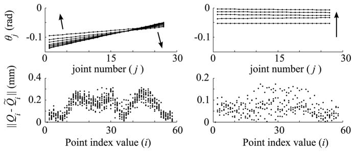
A constant curvature assumption is not adequate to describe manipulator shape at high deflection, as shown in Fig. 12. Virtual notch points (Q̃i) generated using the kinematic model described in Section II are overlaid on actual images of the manipulator. An error metric ||Qi − Q̃i|| between the model and the manually digitized points is defined by the sum of Euclidean distance from each model point to the actual location of its corresponding point. A “best fit” set of θj can be defined by minimizing this error metric.
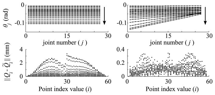
Fig. 12 shows the manipulator for the last point in regime I. While the constant curvature model is fairly close, a “linear model” given by θj = a + bj provides a much closer agreement. Fig. 13 shows the pointwise error for all 58 notch points and all 18 samples in regime I, for both the constant curvature and linear model.
Fig. 13.
Best fit joint angles using constant curvature (left) and linear (right) assumptions, for bending regime I.
Fig. 14 shows pointwise error for the linear model in bending regimes II and III. The arrows in Figs. 13 and 14 indicate the progression of time through the sample set. Over the complete range of configurations, the maximum error using the linear fitting is 0.35 mm, compared to 3.36mmfor the constant curvature fitting.
Fig. 14.
Best fit joint angles using linear curvature assumption, for regime II (left) and regime III (right).
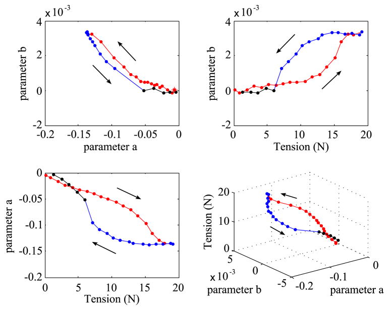
In regime I, the manipulator starts with close to constant curvature. As tension is increased, the joints at the base begin to deflect more than those toward the tip. In regime II, as tension is released, the manipulator remains deflected overall, but the reduction in b shows that the shape is becoming more circular. The base joints, which are deflected most and therefore experiencing the highest force from the flexure joints, move before the other joints that are toward the tip. In regime III the manipulator becomes almost circular as the last of the tension in the cable is released.
B. Physics-Based Model of Bending With Friction
Fig. 15 shows the best-fit shape parameters a and b for the manipulator at each tension during the bending-unbending test shown in Fig. 11. This section presents a simple physical model that captures this behavior. The manipulator is modeled as a series of rigid segments connected by pin joints equipped with torsion springs.
Fig. 15.
Manipulator shape parameters corresponding to the data in Fig. 11. The fitting model is θj = a + bj. Arrows indicate progression with time. See supplemental material for additional test results.
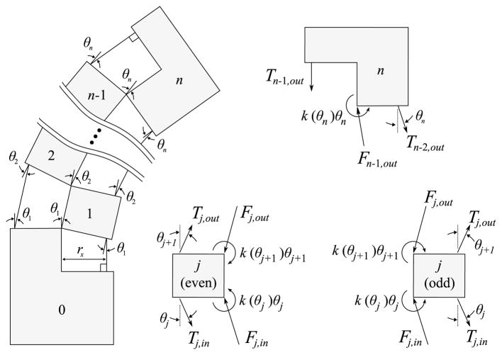
First order dynamics (i.e., overdamped motion) is assumed because we are primarily interested in the equilibrium state of the manipulator. The tension cable and backbone segment are lumped together, with the cable tension propagation dependent on a simple state machine model that represents sliding and static friction between cable and segment. Relative to a given segment, the cable has three states: sliding toward base, sliding toward tip, sticking. Fig. 16 shows the assumed geometry of the cables. Importantly, each cable is parallel to the link opposite it. This assumption is consistent with the geometry discussed in Section II-B. The dynamic modeling algorithm has four steps. Initially, the manipulator is placed at θj = 0, all tension values are set to zero, and at each segment the cable is sticking. The simulation begins when tension is applied to the first two segments.
Fig. 16.
Right: Free body diagrams of link segments in a model that considers cable friction. Cable tension T, backbone compression force F, torsional spring constant k, joint angle θ, and radius to cable rx.
1) Step 1—Tension Propagation
The normal force acting on the cable at each segment is
For each segment, progressing from the base (j = 1) to the tip (j = 27) the tension is propagated as
where μd is the coefficient of sliding friction between cable and backbone segment.
2) Step 2—First Order Dynamics
Summing the dominant forces and moments on a segment provides the first order dynamic model
where τjs = k(θj+1)θj+1 − k(θj)θj and b is a first order damping coefficient.
3) Step 3—Determine Cable Speed
Given the joint angle speeds θ̇i computed in Step 2, the velocity of the cable through each segment is given by
where j ≤ 26 and a positive vcj indicates the cable is sliding through segment j toward the base.
4) Step 4—Determine Stick/Slip State
A simple state machine determines the transitions between three conditions for the cable stick/slip state in each segment. For the jth segment, if the present state is “cable sliding toward base” or “cable sliding toward tip” and the following conditions are met:
the new state is “cable sticking”. If the present state is “cable sticking” and the following condition is met:
the new state is “cable sliding toward base.” If the present state is “cable sticking” and the following condition is met:
the new state is “cable sliding toward tip.” In all other cases the cable state is unchanged. The parameter vcj is a threshold speed below which the cable is assumed to stick, and μs is the static coefficient of friction, μs > μd.
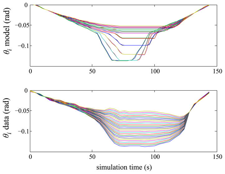
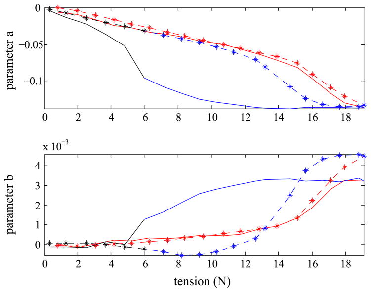
Performance of the model is compared with measured data in Figs. 18 and 19. The only input to this model is cable tension. A value of b = 0.03 Nms/rad is used for the damping term (the results are not especially sensitive to this parameter). The friction terms are μd = 0.29 and μs = 0.30, with vthr = 5× 10⁻⁵ m/s. A piecewise linear torsional spring was used, shown in Fig. 17. The spring rate in the linear region where |θi | < 0.07 rad is equal to 0.4829 Nm/rad. The midrange spring rate for 0.07 ≤ |θi | < 0.14 rad models the “softening” behavior of the superelastic nitinol in high strain. This was necessary for obtaining a good fit to the data in the bending regime.
Fig. 18.
Comparison of measured and predicted backbone joint angles. Top: model prediction. Bottom: best fit to image data using two parameter model θj = a + bj.
Fig. 19.
Comparison of measured and predicted shape parameters. Solid lines: measured data. Dashed lines: predicted. See supplemental material for more results.
Fig. 17.
Piecewise linear torsional spring used to model Nitinol flexure joints and intersegment collisions.
The model performs well in the bending regime across many different tests using different counter-tensions, as can be seen in the animated plots in the supplemental material. The model captures some of the hysteresis behavior, as seen clearly in Fig. 18, however the actual manipulator exhibits a much stronger hysteresis.
V. Conclusion
In Section II, a kinematic model of the backbone and cables was presented. The effect of side to side motion of the cable within the guide channel was considered geometrically, and it was shown that the upper and lower bounds of cable length are very closely approximated by a simple coupling matrix PT of rank 1. While the cable channel width plays an important role in shape bifurcations at high tension, the effects are not important when the joint angles θj are all of the same sign.
In Section III, it was shown that, in general, stiffness is dependent on material properties and not cable tension, at least when neglecting cable friction. Cables with nonlinear stiffness characteristics can allow adjustable stiffness, but only in workspace directions that do not lie in the nullspace of the coupling matrix. Neither the stiffness properties of the backbone nor the cable contribute to the manipulator’s deviation in shape from constant curvature.
In Section IV, it was shown that the manipulator shape was well described by the relation θj = a + bj. Experimental data taken on the manipulator during bending and unbending showed three distinct regimes of behavior (I–III). A physics-based model was presented which works well for the bending in regime I. While the model captures some of the hysteresis shown in the actual robot, it underestimates the duration of sticking of the cables. Additional work is required to develop an improved friction model that captures this behavior.
Acknowledgments
This work was supported by the Independent Research and Development funds provided by the Johns Hopkins University Applied Physics Laboratory.
The authors would like to thank R. Taylor and P. Thienphrapa for their assistance with the LARS robot, and orthopaedic surgeons S. Mears and J. Lepisto, who helped to develop the dexterous manipulator based on the requirements for the treatment of osteolysis. They would also like to thank several anonymous reviewers for carefully reading the first draft of this paper and offering substantial suggestions.
Biographies

Matthew S. Moses received the Ph.D. degree in mechanical engineering from Johns Hopkins University, Baltimore, MD, USA, in 2011.
He was a Postdoctoral Researcher at Johns Hopkins University Applied Physics Laboratory from 2011 to 2012, and is currently a Consultant for industry.

Ryan J. Murphy received the B.S. degree in both aerospace engineering and computer science from the University of Maryland, College Park, MD, USA, and the M.S.E degree in biomedical engineering from Johns Hopkins University, Baltimore, MD.
He is currently working toward the doctoral degree in mechanical engineering at Johns Hopkins University, Baltimore. He is currently an Associate Staff Member at the Johns Hopkins University Applied Physics Laboratory, Laurel, MD. His research interests include medical robots, robot- and computer-assisted surgery, robot kinematics and dynamics, systems and software engineering, and biomechanics.

Michael D. M. Kutzer received the Ph.D. degree in mechanical engineering from the Johns Hopkins University, Baltimore, MD, USA, in 2012.
He was a Staff Researcher at the Johns Hopkins University Applied Physics Laboratory from 2007 to 2014, and is currently an Assistant Professor in the Department of Weapons and Systems Engineering at the United States Naval Academy, Annapolis, MD.

Mehran Armand received the Ph.D. degree in mechanical engineering and the Ph.D. degree in Kinesiology from University of Waterloo, ON, Canada, focusing on bipedal locomotion.
He is a Principal Scientist at the Johns Hopkins University Applied Physics Laboratory (JHU/APL) and holds joint appointments in the Departments of Mechanical Engineering and Orthopaedic Surgery at John Hopkins University, Baltimore, MD, USA. Prior to joining JHU/APL in 2000, he completed postdoctoral fellowships at JHU Departments of Orthopaedic Surgery and Otolaryngology—head and neck surgery. He currently directs the collaborative Laboratory for Biomechanical- and Image-Guided Surgical Systems (BIGSS) within the Center Laboratory for Computational Sensing and Robotics (LCSR) at JHU/Whiting School of Engineering.
Appendix
A detailed treatment of this material is given in [26]. This Appendix reviews the background material and notation that is of most importance for the study presented in this paper. Given an element g ∈ SE(3) represented by a 4 × 4 matrix
where R is a rotation matrix and p is a translation vector, the 6 × 6 adjoint matrix is
The “hat”∧ and “vee” ∨ operators are used to rearrange vector and matrix representations. Hat is used to map 3 × 1 vectors ω = (ω1, ω2, ω3)T to 3 × 3 skew matrices as
and 6 × 1 twists ξ = (v, ω)T to 4 × 4 matrix elements of se(3) as
The vee performs the inverse operations of the hat, i.e., (ω̂)∨ = ω and (ξ̂)∨ = ξ. The spatial manipulator Jacobian is constructed by
where
and
The body manipulator Jacobian is related to the spatial Jacobian by the adjoint
| (27) |
Suppose the end-effector configuration is gst = g(Rst, pst) and we represent a load applied to the manipulator end-effector as two three-element vectors, expressed relative to the world frame: a force f = (fx, fy, fz)T and a torque τ = (τx, τy, τz)T (see Fig. 8). These quantities must be expressed in the end effector frame in order to represent them as a body wrench Ft
The spatial wrench Fs used in (7) is related to the body wrench by the adjoint transpose
| (28) |
where
(28) then evaluates to
Importantly, note that neither the body wrench Ft nor the spatial wrench Fs are equal to (fT, τT)T.
Footnotes
This paper has supplementary downloadable material available at http://ieeexplore.ieee.org provided by the authors. This includes animations in gif format, showing comparison of model and experiment for eight separate test cases. Contact matt.moses@jhu.edu for further questions about this work.
Contributor Information
Matthew S. Moses, Email: matt.moses@jhu.edu, Johns Hopkins University Applied Physics Laboratory, Laurel, MD 20723-6099, USA
Ryan J. Murphy, Email: ryan.murphy@jhuapl.edu, Johns Hopkins University Applied Physics Laboratory, Laurel, MD 20723-6099, USA
Michael D. M. Kutzer, Email: kutzer@usna.edu, Department of Weapons and Systems Engineering, United States Naval Academy, Annapolis, MD 21402 USA
Mehran Armand, Email: mehran.armand@jhuapl.edu, Johns Hopkins University Applied Physics Laboratory, Laurel, MD 20723-6099, USA.
References
- 1.Simaan N, Taylor R, Flint P. A dexterous system for laryngeal surgery,” in. Proc. IEEE Int. Conf. Robot. Autom; 2004; pp. 351–357. [Google Scholar]
- 2.Degani A, Choset H, Wolf A, Zenati MA. Highly articulated robotic probe for minimally invasive surgery,” in. Proc. IEEE Int. Conf. Robot. Autom; 2006; pp. 4167–4172. [DOI] [PMC free article] [PubMed] [Google Scholar]
- 3.Webster RJ, Okamura AM, Cowan NJ. Toward active cannulas: Miniature snake-like surgical robots,” in. Proc. IEEE Int. Intell. Robots Syst. Conf; 2006; pp. 2857–2863. [Google Scholar]
- 4.Rucker DC, Webster RJ, III, Chirikjian GS, Cowan NJ. Equilibrium conformations of concentric-tube continuum robots. Int J Robot Res. 2010;29:1263–1280. doi: 10.1177/0278364910367543. [DOI] [PMC free article] [PubMed] [Google Scholar]
- 5.Cheng WB, Moser MA, Kanagaratnam S, Zhang WJ. Overview of upcoming advances in colonoscopy. Digestive Endoscopy. 2011;24:1–6. doi: 10.1111/j.1443-1661.2011.01181.x. [DOI] [PubMed] [Google Scholar]
- 6.Lee H, Choi Y, Yi BJ. Stackable 4-bar manipulators for single port access surgery. IEEE Trans Mechatron. 2012 Feb;17(1):157–166. [Google Scholar]
- 7.Burgner J, Rucker D, Gilbert H, Swaney P, Russell P, Weaver K, Webster R. A telerobotic system for transnasal surgery. IEEE Trans Mechatron. 2014 Jun;19(3):996–1006. doi: 10.1109/TMECH.2013.2265804. [DOI] [PMC free article] [PubMed] [Google Scholar]
- 8.Kutzer MDM, Segreti SM, Brown CY, Armand M, Taylor RH, Mears SC. Design of a new cable-driven manipulator with a large open lumen: Preliminary applications in the minimally-invasive removal of osteolysis,” in. Proc. IEEE Int. Robot. Autom. Conf; 2011; pp. 2913–2920. [Google Scholar]
- 9.Segreti SM, Kutzer M, Murphy R, Armand M. Cable length prediction for a compliant surgical manipulator,” in. Proc. IEEE Int. Conf. Robot. Autom; 2012; pp. 701–708. [Google Scholar]
- 10.Murphy RJ, Kutzer M, Segreti S, Lucas B, Armand M. Design and kinematic characterization of a surgical manipulator with a focus on treating osteolysis. Robotica. 2013;32:835–850. [Google Scholar]
- 11.Webster RJ, III, Jones BA. Design and kinematic modeling of constant curvature continuum robots: A review. Int J Robot Res. 2010;29:1661–1683. [Google Scholar]
- 12.Kapoor A, Simaan N, Taylor RH. Suturing in confined spaces: constrained motion control of a hybrid 8-dof robot,” in. Proc. Conf. 12th Int. Adv. Robot; 2005; pp. 452–459. [Google Scholar]
- 13.Borghesan G, Palli G, Melchiorri C. Design of tendon-driven robotic fingers: Modeling and control issues,” in. Proc. IEEE Int. Robot. Autom. Conf; 2010; pp. 793–798. [Google Scholar]
- 14.Palli G, Borghesan G, Melchiorri C. Friction and visco-elasticity effects in tendon-based transmission systems,” in. Proc. IEEE Int. Robot. Autom. Conf; 2010; pp. 3890–3895. [Google Scholar]
- 15.Salisbury JK. Active stiffness control of a manipulator in cartesian coordinates,” in. Proc. 19th IEEE Conf. Decision Control Including Symp. Adaptive Processes; 1980; pp. 95–100. [Google Scholar]
- 16.Lee Y-T, Choi H-R, Chung W-K, Youm Y. Stiffness control of a coupled tendon-driven robot hand. IEEE Control Syst. 1994 Oct;14(5):10–19. [Google Scholar]
- 17.Gravagne IA, Walker ID. On the kinematics of remotely-actuated continuum robots,” in. Proc. IEEE Int. Conf. Robot. Autom; 2000; pp. 2544–2550. [Google Scholar]
- 18.Ramos AM, Gravagne IA, Walker ID. Goldfinger: A non-anthropomorphic, dextrous robot hand,” in. Proc. IEEE Int. Robot. Autom. Conf; 1999; pp. 913–919. [Google Scholar]
- 19.Camarillo DC, Milne CF, Carlson CR, Zinn MR, Salisbury JK. Mechanics modeling of tendon-driven continuum manipulators. IEEE Trans Robot. 2008 Dec;24(6):1262–1273. [Google Scholar]
- 20.Gravagne IA, Rahn CD, Walker ID. Large deflection dynamics and control for planar continuum robots. IEEE Trans Mechatron. 2003 Jun;8(2):299–307. [Google Scholar]
- 21.Cheng WB, Di YY, Zhang EM, Moser MAJ, Kanagaratnam S, Korman LY, Sarvazyan N, Zhang WJ. Modeling and in vitro experimental validation for kinetics of the colonoscope in colonoscopy. Ann Biomed Eng. 2013;41:1084–1093. doi: 10.1007/s10439-013-0746-1. [DOI] [PMC free article] [PubMed] [Google Scholar]
- 22.Agrawal V, Peine WJ, Yao B. Modeling of transmission characteristics across a cable-conduit system. IEEE Trans Robot. 2010 Oct;26(5):914–924. [Google Scholar]
- 23.Jung J, Penning RS, Ferrier NJ, Zinn MR. A modeling approach for continuum robotic manipulators: Effects of nonlinear internal device friction,” in. Proc. IEEE Int. Conf. Intell. Robots Syst; 2011; pp. 5139–5146. [Google Scholar]
- 24.Jung J, Penning RS, Zinn MR. A modeling approach for robotic catheters: Effects of nonlinear internal device friction. Adv Robot. 2014;28(8):557–572. [Google Scholar]
- 25.Sun Z, Wang Z, Phee SJ. Elongation modeling and compensation for the flexible tendon–sheath system. IEEE Trans Mechatron. 2014 Aug;19(4):1243–1250. [Google Scholar]
- 26.Murray RM, Li Z, Sastry SS. A Mathematical Introduction to Robotic Manipulation. Boca Raton, FL, USA: CRC Press; 1994. [Google Scholar]
- 27.McCarthy Z, Bretl T. Mechanics and manipulation of planar elastic kinematic chains,” in. Proc. IEEE Int. Robot. Autom. Conf; 2012; pp. 2798–2805. [Google Scholar]
- 28.Kim J-O, Khosla P, Chung W-K. Static modeling and control of redundant manipulators. Robot Comput-Integr Manuf. 1992;9:145–157. [Google Scholar]
- 29.Koganezawa K, Yamazaki M. Mechanical stiffness control of tendon-driven joints,” in. Proc. IEEE Int. Conf. Intell. Robots Syst; 1999; pp. 818–825. [Google Scholar]
- 30.Yamaguchi J, Takanishi A. Development of a biped walking robot having antagonistic driven joints using nonlinear spring mechanism,” in. Proc. IEEE Int. Conf. Robot. Autom; 1997; pp. 185–192. [Google Scholar]
- 31.Kobayahi H, Hyodo K, Ogane D. On tendon-driven robotic mechanisms with redundant tendons. Int J Robot Res. 1998;17:561–571. [Google Scholar]
- 32.Chalon M, Wimbock T, Hirzinger G. Torque and workspace analysis for flexible tendon driven mechanisms,” in. Proc. IEEE Int. Conf. Robot. Autom; 2010; pp. 1175–1181. [Google Scholar]
- 33.Liu WP, Lucas BC, Guerin K, Plaku E. Sensor and sampling-based motion planning for minimally invasive robotic exploration of osteolytic lesions,” in. Proc. IEEE Intell. Robots Syst. Int. Conf; 2011; pp. 1346–1352. [Google Scholar]
- 34.Murphy R, Moses M, Kutzer M, Chirikjian G, Armand M. Constrained workspace generation for snake-like manipulators with applications to minimally invasive surgery,” in. Proc. IEEE Int. Conf. Robot. Autom; 2013; pp. 5341–5347. [Google Scholar]
- 35.Yi BJ, Chung G, Ra H, Kim W, Suh I. Design and experiment of a 3dof parallel micro-mechanism utilizing flexure hinges. IEEE Trans Robot Autom. 2003 Aug;19(4):604–612. [Google Scholar]


