Abstract
The alignment and patterning of cellulose fibers under magnetic fields are reported. Static and rotating magnetic fields were used to align cellulose fibers with sizes ranging from millimeter to nanometer sizes. Cellulose fibers of the millimeter order, which were prepared for papermaking, and much smaller fibers with micrometer to nanometer sizes prepared by the acid hydrolysis of larger ones underwent magnetic alignment. Under a rotating field, a uniaxial alignment of fibers was achieved. The alignment was successfully fixed by the photopolymerization of a UV-curable resin precursor used as matrix. A monodomain chiral nematic film was prepared from an aqueous suspension of nanofibers. Using a field modulator inserted in a homogeneous magnetic field, simultaneous alignment and patterning were achieved.
Keywords: cellulose, magnetic field, magnetic alignment, magnetic patterning
Introduction
Magnetic field is a useful means of processing feeble magnetic materials [1]. Among the many possibilities of magnetic effects, magnetic force and magnetic torque have been extensively studied over the last 10 years and proved useful for materials processing. When a feeble magnetic particle is subjected to a magnetic field gradient, the particle receives a magnetic force so that it is pushed toward the location where the field strength is weak or strong depending on its magnetic nature. This effect is used for separation [2, 3], levitation[4, 5], etc. If a particle has magnetic anisotropy, it undergoes magnetic alignment. Crystallites and fibers are examples of materials having magnetic anisotropy: they can easily align under magnetic fields [6, 7].
Although these magnetic effects have been well known for many years, it is only recently that a number of new techniques have been developed, which provide more sophisticated methods of materials processing. Thin steel wires that can create a local distortion of the field when placed under a homogeneous magnetic field are used for particle separation. This same idea has been applied to the production of a two-dimensional field modulation on a substrate to which microparticles are trapped in a desired pattern. The advantage of this method is that no biological, chemical, or physical surface treatment is needed prior to the patterning. So far, the micropatterning of latex [8], cells, red blood cells [9], carbon nanotubes [10], organic microcrystallites [11], etc has been reported.
Another development is a technique that enables the three-dimensional alignment of biaxial crystals including orthorhombic, monoclinic, and triclinic crystal systems [12]. The idea is based on a dynamically modulated (elliptic) magnetic field. Using this technique, we can prepare a pseudo-single crystal from a powder sample, whose x-ray diffraction pattern is identical with that of a real single crystal [13]. This technique is also useful for materials processing.
Cellulose is produced by green plants and has drawn increasing attention recently owing to its renewable nature. Cellulose, and its regenerated products and derivatives are now utilized as papers, fibers, optical films, matrix for chiral separation, etc. To further expand the utilization of cellulosic materials, innovative methods that help improve and even create various properties in the final products of cellulosic materials are highly required.
We believe that magnetic technique will be one of the promising means to achieve this purpose. A number of studies on the magnetic control of cellulosic materials have already been reported [14–20]. Cellulose exhibits a hierarchical structure ranging from the molecular level to the macroscopic level. By using acid hydrolysis, mechanical treatment, enzymatic treatment, and other methods, large fibers are rendered small. Magnetic field can affect cellulose fibers at various sizes. In this paper, we report our recent work on magnetic alignment and patterning of cellulose fibers.
Experimental
Chiral nematic samples
Chiral nematic samples were prepared from cotton cellulose (Whatman CF 11). The cellulose was mixed with 64% sulfuric acid and stirred at 45 °C for 1h to obtain microfibrils. The acid was removed by centrifugation and prolonged dialysis with pure water until the pH was neutral. The sample was concentrated by evaporation, and the microfibril aggregates were disrupted by sonicating the suspension for 7 min under ice-bath cooling.
Suspensions for alignment under rotating magnetic field
Suspensions were prepared from cotton cellulose (Whatman CF 11). The cellulose was mixed with 4 N hydrochloric acid and the mixture was stirred at 60 °C for 4 h to obtain microfibrils. The acid was removed by centrifugation and prolonged dialysis with pure water until the pH was neutral. The suspending fluid (water) of the microfibrils was replaced with SDS (sodium dodecyl sulfate)-saturated acetone to obtain dried disaggregated microfibrils. The microfibrils were mixed with UV-curable resin (No. 8815 and XVL-14 of Kyoritsu Chemical and Co., Ltd.).
Suspensions for trapping
Suspensions were prepared from cotton cellulose (Whatman CF 11). The cellulose was mixed with 4 N hydrochloric acid and stirred at 60 and 80 °C to obtain microfibrils. The acid was removed by centrifugation and prolonged dialysis with pure water until the pH was neutral. A droplet of the mixture of 1.2 M MnCl2 solution (0.1–0.2 volume) and the cellulose suspension (0.9–0.8 volume) was put on a cover glass placed on a modulator.
Magnetic fields
We used two types of magnetic field: static and rotating. Static fields of 5, 8 and 12 T generated by a cryocooler-cooled superconducting magnet were used. To generate a rotating field, we rotated a sample at 25 rpm in a 12 T static magnetic field instead of rotating a magnet.
Field modulator
The field modulators used were similar to that used in our previous works [8, 9]. They are composed of alternating aluminum and iron sheets of 300 μm thickness, forming a layer structure of 600 μm periodicity. The modulator was fixed in the center of a superconducting magnet generating a horizontal field of 12 T.
Results and discussion
In a static magnetic field, the easy magnetization axis aligns parallel to the applied field to achieve uniaxial alignment, while the hard magnetization axis has a freedom of rotation around the field direction, resulting in a planar alignment on the plane perpendicular to the applied field. The hard magnetization axis of a cellulose fiber is along the fiber's long axis. Therefore, we only obtain a planar alignment of cellulose fibers under a static magnetic field. However, when a suspension of cellulose fibers is cast on a two-dimensional substrate surface by the evaporation of a suspension medium, the rotational freedom of the hard magnetization axis of the fibers is hindered by the surface, and hence a uniaxial alignment of fibers perpendicular to the applied field is achieved.
Figure 1 shows the uniaxial alignment of cellulose fibers obtained under an 8 T magnetic field. Because the fibers are long and have twists and bends, complete orientation was difficult. The strength of the magnetic effect is not intense enough to straighten the fibers by overcoming the twist and bend energy.
Figure 1.

Optical polarizing micrograph (with a color plate) showing magnetic alignment of cellulose fibers. A droplet of pulp suspension used for papermaking was cast on a slid glass and water is allowed to be evaporated under a static magnetic field of 8 T. The arrow indicates the direction of the magnetic field.
Under a rotating magnetic field, the hard magnetization axis aligns perpendicular to the plane of rotation of the field, while the direction of the easy magnetization axis is not fixed. Depending on the rotation speed ω and the intrinsic rate τ−1 of magnetic alignment, there are two extreme cases. If ωτ≫1, the easy axis cannot follow the field rotation, and the motion of the hard axis becomes similar to that of the easy axis under a static field. The final direction of the easy axis depends on its initial direction. If ωτ<1/2, the easy axis can follow the field rotation, and therefore, its direction is not fixed. In both cases, the hard axis aligns uniaxially.
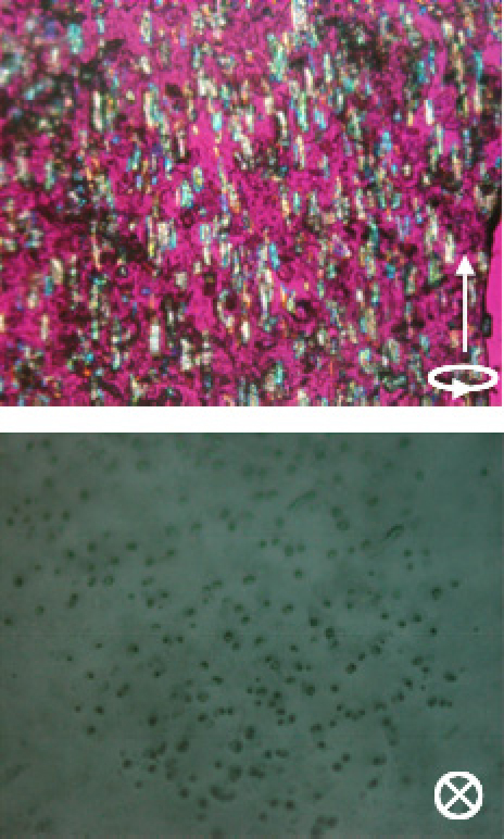
Figure 2 shows the uniaxial alignment of cellulose fibers prepared by the acid hydrolysis of wood pulp. The fibers are short, exhibit no twist or bend, and are aligned uniaxially. The side view is taken from a sliced piece cut from the block sample and the top view is the observation of the top surface of the block sample. The micrographs clearly show the uniaxial alignment. Although the fibers are aligned, the color of the individual fibers viewed under a color plate differs from fiber to fiber. This might be due to the biaxial nature of cellulose crystals: depending on the direction of observation, birefringence differs. Thus, the preparation of a resin/fiber composite with a high fiber concentration is possible.
Figure 2.

Polarized microscopic observation (with a color plate) of uniaxial alignment of cellulose fibers achieved by sample rotation (25 rpm) in a static magnetic field of 12 T. The arrow indicates the rotating axis of the field. Alignment is fixed by the photopolymerization of the UV-curable resin precursor used as a matrix. Side view (top) and top view (bottom) clearly indicate the uniaxial alignment.
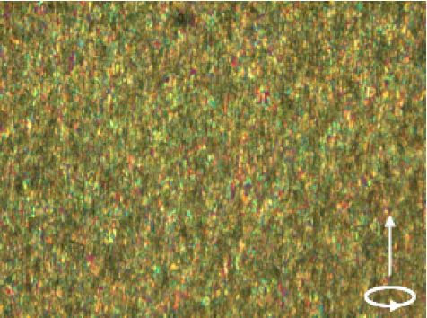
Figure 3 shows the uniaxial magnetic alignment of cellulose fibers in a UV-cured resin. The fiber concentration is higher than that shown in figure 3. Here again, a high alignment is achieved.
Figure 3.

Polarized microscopic observation (with a color plate) of uniaxial alignment of cellulose fibers achieved under a rotating magnetic field (the arrow indicates the axis of rotation). Cellulose fibers dispersed in a resin precursor (XVL-14) was sandwiched between two cover glasses and rotated at 25 rpm in a static magnetic field of 12 T. Alignment was fixed by the photopolymerization of the UV-curable resin.
By acid hydrolysis of pulp fibers or other sources of cellulose fibers, a suspension of cellulose nanocrystallites is obtained. Owing to the ionic unit introduced into the fiber surface by the chemical treatment, the sample forms a stable suspension that exhibits a chiral nematic liquid crystalline phase. In a chiral nematic phase, individual nanofibers are oriented perpendicular to the helical axis of the chiral nematic phase. Therefore, upon the application of a static magnetic field, the helical axis aligns parallel to the field. On the other hand, under a rotating magnetic field, helices tend to untwist to form a nematic phase [17].
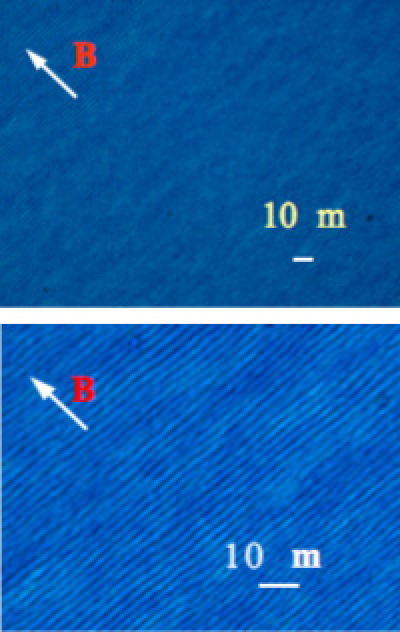
Figure 4 shows a chiral nematic film prepared by casting a suspension in a static magnetic field. The fingerprint texture characteristic of the chiral nematic phase is maintained after the evaporation of the liquid medium. Without magnetic field, only a film with a multidomain structure was obtained.
Figure 4.

Polarized microscopic observation of monodomain of chiral nematic film obtained under 12 T magnetic field. The photograph on the right shows enlargement. A fingerprint texture pattern is clearly observed.
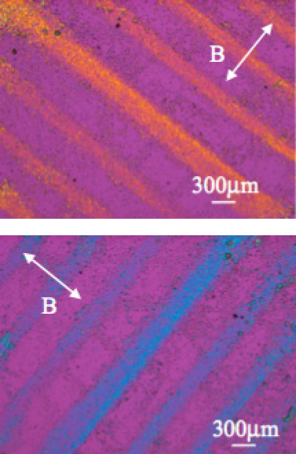
Under a modulated magnetic field generated on a substrate surface by a field modulator, microparticles are trapped in the field minima. We have reported the micropatterning of various particles including poly(styrene) latex [8], cells [9], carbon nanotubes [10], bacterial cellulose, etc. In the case that the particles to be trapped have magnetic anisotropy, they could also undergo magnetic alignment. Figure 5 shows the magnetic trapping and alignment of cellulose fibers. The different colors observed with a color plate clearly indicate the orientation of the fibers in the patterned lines.
Figure 5.

Magnetic micro-patterning and alignment of cellulose fibers observed under polarizing microscope with color plate. The different colors of the patterned lines indicate that fibers are oriented. The line in the middle is about two times wider because the width of the corresponding iron layer of the modulator is two times larger.
Conclusion
We have shown the magnetic alignment and patterning of cellulose fibers with various sizes. Since the fiber axis of a cellulose fiber corresponds to the hard magnetization axis, only planar alignment is achieved under a static field except in the case that the rotational freedom around the hard axis is hindered by the existence of a two-dimensional surface. To align the fiber axis, the use of rotating field can be used. It was shown that uniaxial fiber alignment in the bulk is achieved using the rotating field. Actually, the rotating field was realized by rotating a sample in a static field. The helical axis of a chiral nematic phase of a suspension of cellulose nanofibers was aligned under a static field. A film cast from a chiral nematic suspension in a static magnetic field exhibited a monodomain structure. The simultaneous alignment and patterning of cellulose fibers was achieved using a field modulator. The magnetic technique will provide a powerful means for processing cellulose fibers.
Acknowledgment
This work was partially supported by the JSPS Asian Core Program ‘Construction of the World Center on Electromagnetic Processing of Materials’.
References
- Kimura T. Polym. J. 2003;35:823. doi: 10.1295/polymj.35.823. [DOI] [Google Scholar]
- Hirota N, Ikezoe Y, Uetake H, Kaihatsu T, Takayama T. and Kitazawa K. Mater. Res. Soc. Japan. 2002;27:47. [Google Scholar]
- Kimura T, Mamada S. and Yamato M. Chem. Lett. 2000;29:1294. doi: 10.1246/cl.2000.1294. [DOI] [Google Scholar]
- Beaugnon E. and Tournier R. Nature. 1991;349:470. doi: 10.1038/349470a0. [DOI] [Google Scholar]
- Ikezoe Y, Hirota N, Nakagawa J. and Kitazawa K. Nature. 1998;393:749. doi: 10.1038/31619. [DOI] [Google Scholar]
- Fujiwara M, Chidiwa T, Tokunaga R and Tanimoto Y. 1998. Phys. J. Chem. B 102 3417 10.1021/jp980289v [DOI] [Google Scholar]
- Kimura T, Yamato M, Koshimizu W, Koike M. and Kawai T. Langmuir. 2000;16:858. doi: 10.1021/la990761j. [DOI] [Google Scholar]
- Kimura T, Yamato M. and Nara A. Langmuir. 2004;20:572. doi: 10.1021/la035768m. [DOI] [PubMed] [Google Scholar]
- Kimura T, Sato Y, Kimura F, Iwasaka M. and Ueno S. Langmuir. 2005;21:830. doi: 10.1021/la047517z. [DOI] [PubMed] [Google Scholar]
- Piao G, Kimura F, Takahashi T, Moritani Y, Awano H, Nimori S, Tsuda K, Yonetake K. and Kimura T. Polym. J. 2007;39:589. doi: 10.1295/polymj.PJ2006191. [DOI] [Google Scholar]
- Piao G, Kimura F. and Kimura T. Langmuir. 2006;22:4853. doi: 10.1021/la053505h. [DOI] [PubMed] [Google Scholar]
- Kimura T. and Yoshino M. Langmuir. 2005;21:4805. doi: 10.1021/la050182g. [DOI] [PubMed] [Google Scholar]
- Kimura T, Kimura F. and Yoshino M. Langmuir. 2006;22:3464. doi: 10.1021/la053479n. [DOI] [PubMed] [Google Scholar]
- Sugiyama J, Chanzy H. and Maret G. Macromolecules. 1992;25:4232. doi: 10.1021/ma00042a032. [DOI] [Google Scholar]
- Revol J-F, Godbout L, Dong X-M, Gray D G, Chanzy H. and Maret G. Liq. Cryst. 1994;16:127. doi: 10.1080/02678299408036525. [DOI] [Google Scholar]
- Cranston E D. and Gray D G. Sci. Technol. Adv. Mater. 2006;7:319. doi: 10.1016/j.stam.2006.02.007. [DOI] [Google Scholar]
- Kimura F, Kimura T, Tamura M, Hirai A, Ikuno M. and Horii F. Langmuir. 2005;21:2034. doi: 10.1021/la0475728. [DOI] [PubMed] [Google Scholar]
- Kimura T. and Kimura F. Cellulose Commun. 2006;13:193. [Google Scholar]
- Kvien I and Oksman K. 2007. J. Appl. Phys. A 87 641 10.1007/s00339-007-3882-3 [DOI] [Google Scholar]
- Kimura T, Kamioka T. and Kuga S. Polym. J. 2007;39:1199. doi: 10.1295/polymj.PJ2006189. [DOI] [Google Scholar]


