Abstract
To achieve breakthroughs in the areas of heliospheric and magnetospheric energetic neutral atom (ENA) imaging, a new class of instruments is required. We present a high angular resolution ENA imager concept aimed at the suprathermal plasma populations with energies between 0.5 and 20 keV. This instrument is intended for understanding the spatial and temporal structure of the heliospheric boundary recently revealed by Interstellar Boundary Explorer instrumentation and the Cassini Ion and Neutral Camera. The instrument is also well suited to characterize magnetospheric ENA emissions from low‐altitude ENA emissions produced by precipitation of magnetospheric ions into the terrestrial upper atmosphere, or from the magnetosheath where solar wind protons are neutralized by charge exchange, or from portions of the ring current region. We present a new technique utilizing ultrathin carbon foils, 2‐D collimation, and a novel electron optical design to produce high angular resolution (≤2°) and high‐sensitivity (≥10−3 cm2 sr/pixel) ENA imaging in the 0.5–20 keV energy range.
Keywords: ENA, heliospheric imaging, magnetospheric imaging, energetic particles, measurement techniques, instrument
Key Points
The LENI instrument is capable of high angular resolution ENA imaging
The LENI instrument utilizes novel MCP collimation for ENA imaging
The LENI instrument is designed for heliospheric and magnetospheric imaging
1. Introduction
Energetic Neutral Atoms (ENAs) are produced by charge exchange processes between energetic ions and neutral gasses. As ions, these particles are constrained by the Lorentz force to their local magnetic fields; however, once they are neutralized they are not influenced by electromagnetic forces and travel on ballistic paths. Imaging this ENA emission from charged particle‐gas interaction regions is analogous to imaging photon emission from a glowing gas cloud and therefore a useful remote sensing technique for such regions.
There are several areas of scientific interest for ENA imaging. Here we motivate two specific scientific questions that a low‐energy, high angular resolution instrument would address: (1) to understand the spatial and temporal structure of the heliospheric boundary and (2) to understand the spatial structure of magnetospheric ion precipitation into the upper atmosphere. Other topics such as imaging the terrestrial ring current and the subsolar magnetopause are of great interest and could be probed with this instrument, but we do not go into detail on these specific implementations here.
The Interstellar Boundary Explorer (IBEX) mission [McComas et al., 2009a] and the Voyagers produced breakthroughs in our understanding of the interaction between the Sun and its local galactic neighborhood [e.g., Stone et al., 2005; Decker et al., 2005; McComas et al., 2009b]. This new frontier of heliospheric physics is fundamental to our understanding of the influence of the solar wind on the local interstellar medium, and vice versa. The structure and dynamics of this interaction as imaged by IBEX‐Lo [Fuselier et al., 2009], IBEX‐Hi [Funsten et al., 2009], and the Cassini magnetosphere imaging instrument (MIMI) Ion and Neutral Camera (INCA) [Krimigis et al., 2004] hint at the physical processes at play in this region. In situ measurements by the Voyager 1 and 2 interstellar probes have revealed that this region is a wholly new plasma regime in which the nonthermal energetic particles dominate the pressure balance and define the structure of the interaction.
The IBEX and Cassini INCA ENA images (e.g., Figure 1) fundamentally challenged our preexisting picture of the interaction between the solar wind and the interstellar medium. For instance, the shape of the interaction had long been supposed to be simply an elongated, cometary‐like interaction suggested by planetary magnetospheres as well as by remote observations of other astrospheres [e.g., McComas et al., 2009c]. However, an alternate configuration of a diamagnetic bubble was also proposed by Parker [1961] and was invoked to interpret the ENA observations of Krimigis et al. [2009]. Our best hopes for the resolution of this fundamental theoretical dichotomy lie in the order‐of‐magnitude improvement in observations that will span the energy ranges of the observations that underlie the IBEX and INCA measurements and better resolve the spatial, energy and temporal structure of this crucial interaction region. Of special interest is the fine structure of the “ribbon” feature shown in the inset B of Figure 1 (top) [McComas et al., 2011] and the pronounced “knot.” This feature appears to have fine structures that lie beyond the IBEX angular resolution; in addition, their spectral indices are different [Dayeh et al., 2011]. Separating these features and their energy spectra will allow for better understanding of the underlying physics.
Figure 1.
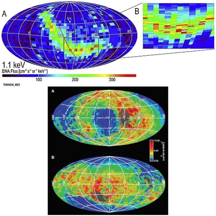
Heliospheric ENA maps from (top) IBEX−Hi and (bottom) Cassini INCA demonstrating the energy dependence of the spatial features. [McComas et al., 2011; Krimigis et al., 2009].
The second area of scientific interest for high angular resolution ENA imaging is the region of low‐altitude emission (LAE) in the Earth's magnetosphere. Large numbers of energetic ions from the inner magnetosphere continuously precipitate and interact with the upper atmosphere through a complicated cascade of reactions (charge exchange, stripping, ionization, and excitation) that change their state from charged to neutral several hundreds of times. Contrary to common belief, precipitating ions are not all lost to the atmosphere, but up to 30% or more escape upward as neutrals and ions through a particle albedo effect (Figure 2) [e.g., Bazell et al., 2010]. This has fundamental consequences on how we understand the energy transfer to the atmosphere and how magnetospheric particles are lost.
Figure 2.
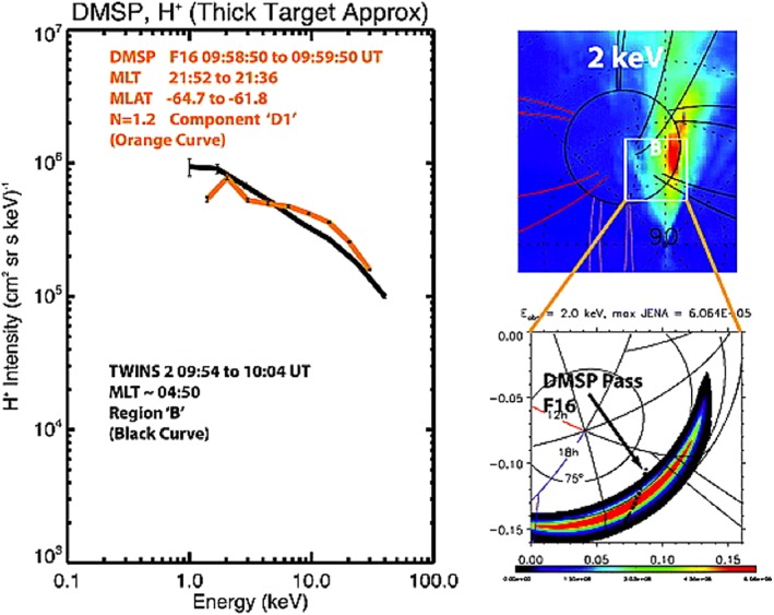
IMAGE HENA and TWINS demonstrated that magnetospheric ion precipitation leads rather to an intense albedo of backscattered ENAs (or LAE), than to an empty upward loss cone. The ENA emissions come from a thin (~10 km) layer at about 300 km altitude [Bazell et al., 2010].
There is a clear scientific need for new instrumentation that can better resolve the energy and angular distribution of ENAs. Our answer to this scientific call is the Low‐Energy Neutral Imager (LENI), which utilizes novel methods in ENA imaging. From a sounding rocket, cubesat, small satellite, or spacecraft in orbit, LENI would image the distribution of the bright LAE of ENAs emitted as a result of magnetospheric ion precipitation into and backscattering from the upper atmosphere. Bazell et al. [2010] show that this emission comes from a ~10 km layer at roughly 300 km altitude. To obtain 5 km resolution in this region with a 2° imager we would have to be within 140 km meaning that imaging from low Earth orbit is possible.
2. Technique
Traditionally, ENA measurements have used either charge conversion surfaces or thin foils to convert the neutrals into ions or produce electrons that can contribute to measuring the energy, composition, and/or velocity of the ENA. With a charge conversion surface, incident ENAs graze the surface picking up or losing an electron in the process, while with carbon foils the ENA traverses the foil releasing electrons from its surfaces. For very low‐energy ENAs it is not possible to use the carbon foil technique as the particle cannot penetrate even the thinnest foil, hence the preference for charge conversion surfaces for very low energy (tens of eV) instruments. For high‐energy ENAs, foils have generally been used, and their angular resolution has been satisfactory due to the modest angular scattering of these high‐energy neutrals in the foils. However, for the medium‐energy (500 eV to 20 keV) range both ultrathin carbon foils and charge conversion surfaces have been used. Charge conversion surfaces tend to be inefficient, with ionization efficiencies of 2–5% at 1 keV [e.g., Fuselier et al., 2009]. Carbon foils degrade angular and energy resolution by scattering low‐energy ENAs through large angles (for a 0.6 ug/cm2 foil the half angle scattering at 1 keV is about 19°; [Funsten et al., 2009]). IBEX‐Hi successfully dealt with the large scattering angle by precollimation to ~4° and only analyzing the charged fraction exiting the foil (~7% at 1 keV) instead of the much more abundant neutral fraction (~93% at 1 keV) [Funsten et al., 2009]. Figure 3 details the techniques used for four instruments that have been produced for ENA detection for some portion of the 500 eV to 10 keV energy range. Gruntman [1997] and Scime and Zaniewski [2004] provide comprehensive reviews of ENA imaging techniques.
Figure 3.
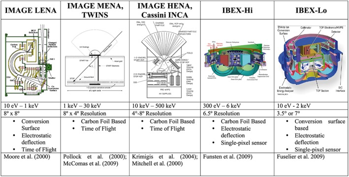
The techniques used previously for ENA detection.
We propose to change the paradigm of low‐ to medium‐energy (0.5 keV–20 keV) ENA imaging by tightly collimating the incoming ENA beam and directly imaging the incoming particles as they traverse the start foil. The instrument concept is shown in Figure 4 and the instrument capabilities are given in Table 1. An ENA enters the instrument through a single, zero‐bias angle microchannel plate (MCP) providing 2° × 2° or better collimation. Immediately after exiting the entrance MCP, the ENA traverses a ~0.5 µg/cm2 ultrathin carbon foil producing both start and coincidence electrons from both sides of the foil. The start electron from the entrance side of the foil is then accelerated back through the entrance MCP where it produces an electron cascade that is imaged by a delay line anode on the start MCP (chevron stack). The coincidence electron from the back of the first foil is accelerated by a 1 kV potential through a second ~0.5 µg/cm2 foil, which the ENA also traverses producing a stop electron. Due to the 1 kV acceleration of the coincidence electrons, they fall onto a region of the stop/coincidence MCP separate from the stop electrons produced on the second foil by the ENA. The start electron provides both timing and spatial resolution. The coincidence and stop electrons provide both timing and spatial coincidences that are used to efficiently remove background signals. The following gives a detailed description of each region of the instrument.
Figure 4.
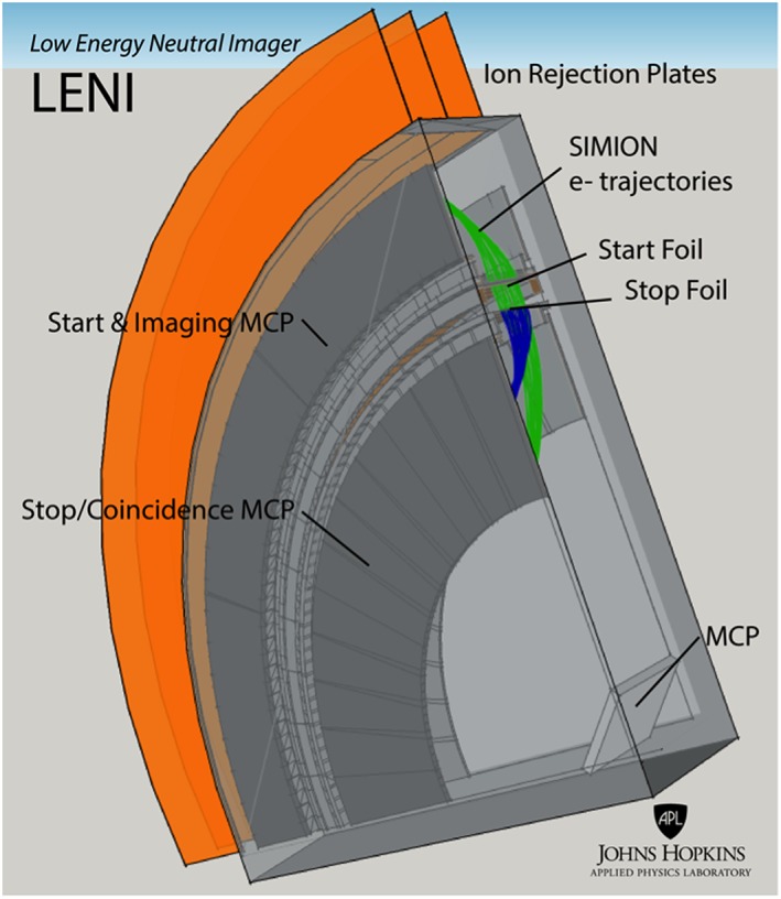
A conceptual drawing of the Low‐Energy Neutral Imager (LENI).
Table 1.
The Predicted LENI Instrument Performance
| Parameter | LENI |
|---|---|
| Measurement | ENAs, ions |
| Energy range | 0.5 keV–20 keV |
| Resolution, ΔE/E | 20% at 1 keV |
| Instantaneous FOV | 48 × 2°×2° pixels |
| Instantaneous full FOV | 96° × 2° |
| Coverage (spinning spacecraft) | 96° × 360° in one revolution |
| Geometric factor | 10−3 cm2 sr (per pixel) |
| 9.6 × 10⁻² cm2 sr (instantaneous full FOV) | |
| TOF path length | 0.5 cm |
2.1. Electron Optics
LENI, like the Jupiter Icy Moon Explorer (JUICE) Jovian Energetic Neutrals and Ions (JENI) Mitchell et al. [2016], Cassini INCA [Krimigis et al., 2004], and Image HENA [Mitchell et al., 2000] relies on acceleration and steering of secondary electrons by electrostatic fields to achieve both accurate timing and position resolution required for imaging ENAs. The LENI electron optical design has the following advantages over previous generation ENA imagers:
The image is produced from the entrance to the first foil prior to angular scattering and energy straggling, reducing the effects of scattering in the image.
Narrow stop and coincidence timing windows result in a large reduction of the background.
Spatial coincidence between the start, stop, and coincidence signals for additional background rejection.
Particle detection does not rely on charge conversion through the carbon foils or onto a charge conversion surface.
LENI utilizes a variation of the mirror‐free electron optics developed and flown successfully for the hockey puck style ion detectors (New Horizons PEPSSI [McNutt et al., 2009], Van Allen RBSPICE [Mitchell et al., 2013], Juno JEDI [Mauk et al., 2013], MMS‐EIS [Mauk et al., 2014]). This electron optical arrangement operates by placing a puller electrooptical element toward the MCP and a pusher element above as shown in the electron optical SIMION simulation in Figure 5. The 1 kV stop foil accelerates the electrons from the backside of the start foil which are then detected on the same MCP as the stop electrons. The exit of the second foil is nearly identical to the region above the entrance MCP and has been modified slightly to accommodate both the electrons produced on the second foil and the accelerated electrons from the first foil. We note that the 1 kV accelerated electrons do not interact strongly with these thin foils and can therefore be efficiently accelerated through the foil with minimal losses. Extrapolating the experimental data from Kanter [1961] results in a critical energy (the energy required to transmit through the foil) of ~100 eV and an energy loss of under 10%. Because ~1 kV electrons are much faster than any of the ENAs for which this instrument is designed, false stops generated by those few coincidence electrons that do generate secondaries at the exit surface of the Stop foil will generate a TOF too short for a valid ENA, and the false event will be rejected.
Figure 5.
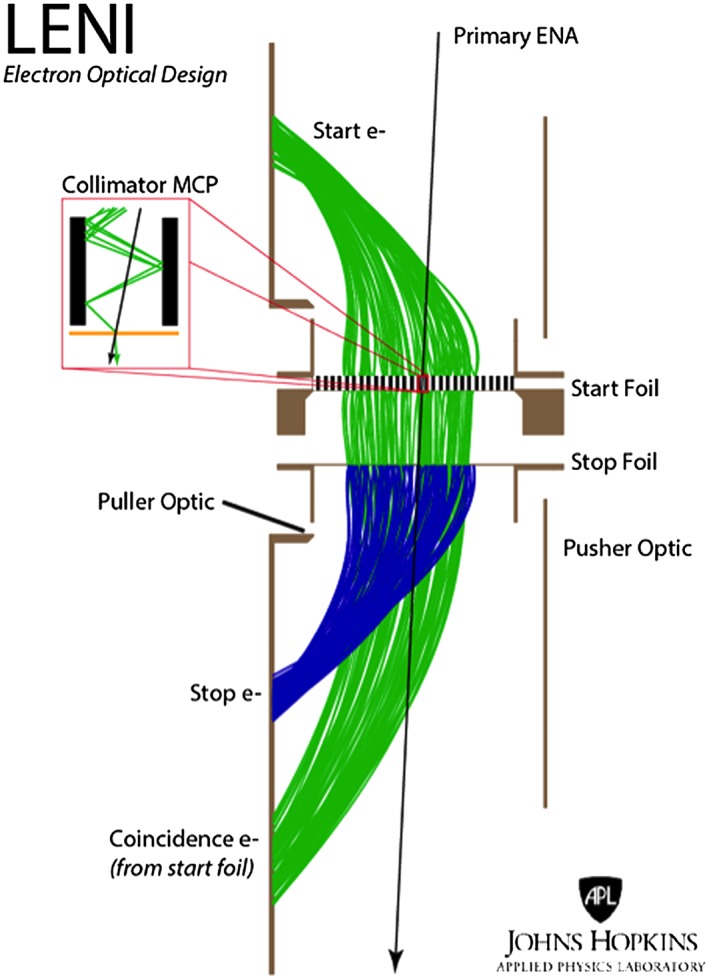
The electron optics design of LENI is optimized for high angular and energy resolution imaging. The figure shows a SIMION 2‐D simulation of trajectories through the LENI instrument. Black shows the path of the primary ENA through the collimator and start and stop foils. The green shows the start and coincidence electrons derived from the back and front of the start foil, respectively. The blue shows the paths of the stop electrons produced on the stop foil. The inset shows how the collimator MCP doubles as an electron multiplier producing a large start signal.
2.2. MCP Collimation
LENI utilizes a novel approach to high angular resolution by collimating the ENAs as they enter the instrument. Collimation to 2° × 2° is provided by a zero‐bias angle MCP. Figure 6 shows the measured Am241 alpha transmission through our prototype LENI collimator. We note that though the Am241 alpha has an energy of 5.486 MeV, lower energy ions will behave similarly in this collimator. This collimator consists of a Photonis 0° bias angle 50:1 MCP with 25 µm pores in a 12 × 11 mm rectangular configuration (Figure 7). ENAs, along with other unwanted signal producers (i.e., photons, ions) that strike the side walls of the MCP channels will produce secondary electrons in the MCP; however, they will not produce the crucial stop and coincidence electrons from either of the foils. At angles slightly outside of the 2° mechanical collimation, some particles will forward scatter or produce knock‐on sputtering of water molecules on the MCP channel surface resulting in H atoms and ions that could masquerade as the original ENA or ion and contribute to imaging artifacts [e.g., Möbius et al., 2012]. These contributions will result in potentially significant broadening of the angular response of the sensor. The primary advantage of using an MCP for the start collimator is that we can place this collimator directly on top of the start foil. Since 2° × 2° collimation requires very high aspect ratio collimation, it is difficult to electrostatically pull electrons through a metallic collimator. This is because the secondary electrons will come off of the foil with a cosine distribution and will typically collide with the walls of this collimator and be lost to this interaction. However, with the MCP collimator, the electron interacts with the walls of the MCP and produces a cascade of electrons that can exit the collimator providing both a fast and amplified start signal that maintains the spatial resolution of the collimator. The collimator MCP design will not suffer from ion feedback due to the separation of the collimator from the start MCP; ions produced in the MCP collimator will not travel to the start MCP due to the electron optics.
Figure 6.
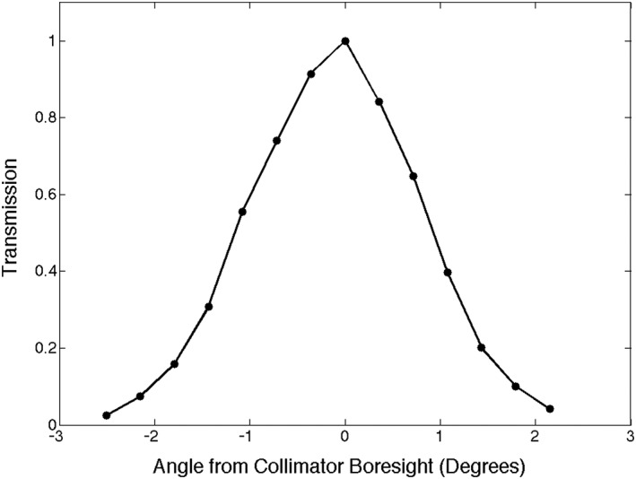
Measured transmission of 5.486 MeV alphas from an Am241 source through the LENI MCP collimator as a function of incident beam angle θ, where θ = 0° corresponds to the boresight direction.
Figure 7.
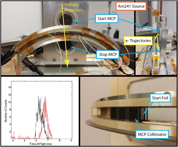
The APL LENI breadboard test setup. The curved LENI collimator is populated by 3 pixels and ultrathin carbon foils. The top left figure shows the test setup with the timing start and stop MCPs. The top right figure shows the predicted electron trajectories. The bottom left figure shows the measured coincidence time between the start and stop MCP when tested using Am241 alphas through the system (5.486 MeV) with the black curve showing with the source is pointed down and the red curve with the source on the opposite side of the TOF assembly pointed up through the instrument. The bottom right figure shows a close‐up of the MCP collimator and foil.
2.3. Ultrathin Carbon Foils
LENI is designed to use 0.5 µg/cm2 amorphous carbon foils backing the collimator MCP for the start signal. These foils have been the standard workhorse for low‐energy plasma and ENA measurements and have proven robust when handled and mounted carefully. These foils allow for the transmission of low‐energy ENAs (down to below 500 eV) and for the production of electrons from the surfaces for detection. Recent publications by Allegrini et al. [2014] and Ebert et al. [2014] have shown promising results using graphene foils. They have demonstrated substantial reductions in angular scattering at low energies, especially for heavier species such as oxygen, as well as reductions in energy straggling when using these foils. If grapheme proves to be a superior choice to amorphous carbon foils, we will work toward incorporating graphene in the LENI design.
2.4. Charged Particle Deflection System
Typical methods for rejecting unwanted charged particles include the use of a deflection system consisting of biased conducting plates in front of the collimator as was done on the INCA [Krimigis et al., 2004], HENA [Mitchell et al., 2000], and MENA [Pollock et al., 2000] designs. Due to the electric field between these deflection plates, charged particles in and slightly above the instrument energy range are forced into the plate surface, thus prohibiting them from entering the collimator and therefore reducing spurious counts. Further methods used in reducing unwanted signal involve serrating the surface of the plates to inhibit forward scattering. Note that the charged particle deflection system is not used for collimation and is purposely placed out of the LENI field of view (FOV). The LENI charged particle deflection system is a reconfiguration of the same subsystem used effectively on the Cassini INCA and IMAGE HENA sensors where they typically reduced ambient ion intensities by 4 orders of magnitude or more and ambient electron intensities by 2 to 3 orders of magnitude. The LENI implementation employs two electrostatic charged particle deflection plates that are biased alternately at ground and up to +6 kV. The charged particle deflection plates are placed outside of the LENI FOV such that ion‐to‐neutral conversion effects and forward scattering of ions into the collimator is minimized. A set of outer grounded plates provide a suitable EMI/EMC environment to the spacecraft and the HV plate is recessed such that the field protrusion is minimized allowing for accommodation near other fields and particles instrumentation. The voltage on the charged particle deflection system can be turned off to allow for direct ion observations. Electrostatic simulations for the arrangement reject incoming charged particles with energies up to 200 keV/q, well outside of the LENI energy range.
Previous ENA sensors in the 1 keV range have reported artifacts in their data due to ion conversion on surfaces in front of the entrance aperture and electron impact‐generated ion beam effects ahead of the aperture. Ion conversion is inevitable on the rejection plates as particles will interact with the surfaces producing either ions or neutrals as a result. If a resultant neutral particle is forward scattered with little energy loss, then it can be mistakenly identified as an unscattered ENA. To minimize this contribution the charged particle deflection plate surfaces are serrated such that forward scattering is largely eliminated. This was the successful approach of the IMAGE‐HENA and Cassini INCA ENA sensors.
2.5. UV and Penetrator Rejection Through Timing and Spatial Coincidence
Previous ENA sensors in this energy range have required light traps, electrostatic analyzers, or gold gratings to reject the ambient UV environment, at considerable cost to sensitivity. UV photons produce unwanted MCP signals that can drive the system noise. We approach UV rejection by utilizing tight spatial and timing coincidence measurements.
INCA and HENA used moderately thin, grid‐mounted foils in their entrance slits as well as covering the Stop MCP. In HENA and INCA, these foils serve the dual purpose of producing secondary electrons as primary particles penetrate them, and reducing UV and visible light so that UV‐generated photoelectrons do not overdrive the MCP counting rates. For HENA and INCA, the Start foils were designed to reduce the FUV‐ and EUV‐related counting rates to ≤105/s or less, which in the case of INCA required a ~10 µg/cm2 Start foil thickness, whereas for HENA, in the brighter Earth environment, the Start foil thickness was 15 µg/cm2. The Stop foils in each were ~7 µg/cm2. These foils resulted in accidental rates consistent with the formula R acc = R Start × R Stop × W TOF ≤ 105 × 103 × 10−7 ≤ 10 s−1 where R Start and R Stop are the Start and Stop UV rates and W TOF is the window for valid time of flight.
Of course, these foils could have been made even thicker, eliminating even more of the UV photon flux, but the thickness of the foils, particularly the Start foil, limits the minimum energy ion or ENA that can penetrate both foils and reach the Stop MCP. Furthermore, those particles that are sufficiently energetic are still scattered in angle and lose some energy in transiting the Start foil, so the thinner the foil, the lower the energy loss and the less the scattering.
The JENI and LENI approach to the start foils is to eliminate the requirement that they act as photon filters. Therefore, the Start foils, relieved of any requirement on UV suppression, may be made as thin as feasible, consistent with surviving launch and providing a source of secondary electrons. Traditional plasma analyzers routinely use grid‐mounted carbon foils of 1 to 2 µg/cm2 thickness. The IBEX‐Hi ENA instrument employs foils ~0.6 µg/cm2 covering its entire aperture of 156 cm2, tiled in individual foils each ~10.5 cm2. The IBEX‐Hi foils survived launch intact and continue to function nominally after 7 years in orbit. Based on this experience as well as laboratory tests, LENI will use ~0.5 ‐ 1 µg/cm2 start foils. The stop foil is also ~0.5–1 µg/cm2, to permit secondary emission from its exit side down to low‐ENA incidence energy. Because the foils are not relied upon as photon filters, our design is highly tolerant to loss of foil area to broken grid cells that may occur during launch, or in manufacture or handling. Individual cell loss affects only sensitivity (sensor efficiency), so lost foil area on the order of 10% or even more has only minor impact on science.
Mission design and accommodation would be made such that the Sun was kept out of the instrument FOV, limiting the UV to such sources as Earth shine (reflected or reemitted solar UV) and interstellar Lyman alpha. Experience with both INCA and HENA showed that the serrated charged particle deflection plate surfaces forward scattered very little light, reducing the keep‐out zone around the Sun to <5° from direct entry. The interstellar Lyman alpha UV is roughly ≤1.5 kR at Earth resulting in rates from UV of ~104/s per pixel for each foil surface. The accidental rate per pixel would be R acc = R start · R coin · R stop · W TOF · W coin ≤ 104 × 104 × 104 × 10−7 × 10−9 ≤ 1 × 10⁻⁴ s−1 where R coin is the UV‐induced rate from the back, coincidence side of the start foil, and R stop is the stop rate. We compare this expected noise rate with that of IBEX‐Hi, which was measured to be 5.8 × 10⁻⁴ Hz for triple coincidence [Funsten et al., 2009]. The primary reason for the relatively small UV rate on the LENI detectors comes from the small geometric factor per pixel of 10−3 cm2 sr. The high‐voltage side of the MCP is facing out meaning that UV that strikes the top of the MCP or high in the pores will lead to very little or no electron multiplication. In addition, the charged particle deflection system blocks UV from a large swath of the sky. For a heliospheric mission the spacecraft would likely be a Sun‐pointed spinning platform, in which case the instrument can be accommodated without allowing the Sun (or solar wind) into the FOV. For a magnetospheric mission keeping the Sun out of the FOV can be more difficult, but experience from IMAGE shows that it is possible with careful mission design.
Penetrators result in low rates of TOFs, all shorter than those for foreground particles, and so recognized as invalid by the valid event processing. Based on laboratory measurement as well as in‐flight performance of HENA and INCA, the serrated plates reduce ambient charged particle intensities by at least 4 orders of magnitude within the sensor energy range. The INCA serrated plate performance was measured at ~200 keV, in the 0.5 to 20 keV range required here we expect similar or greater rejection efficiency due to increased forward scattering at higher energies. For a heliospheric imaging mission the instrument should be placed into an orbit with low penetrating radiation and the shielding would be minimal. For a magnetospheric mission careful instrument shielding could be applied to reduce counts from penetrators.
3. Conclusions
We have presented the Low‐Energy Neutral Imager (LENI) instrument concept. This instrument is a novel solution to high angular resolution ENA imaging in the energy range from 0.5 to 20 keV. The novel MCP collimator technique along with the use of ultrathin carbon foils will produce scatter free images with 2° angular resolution. Our calculations of the expected noise rates and detection efficiencies have shown that LENI could successfully image the heliospheric boundary at higher angular resolution than IBEX‐Hi or Cassini INCA and the magnetospheric low‐altitude emission and thus LENI present a significant technological advancement to the current state‐of‐the‐art in ENA imaging techniques.
Acknowledgments
We would like to acknowledge NASA H‐TIDES grant NNX15AK46G for supporting this work. Interested readers can access the data in this article by e‐mailing joseph.westlake@jhuapl.edu.
Westlake, J. H. , Mitchell D. G., Brandt P. C.‐s., Andrews B. G., and Clark G. (2016), The Low‐Energy Neutral Imager (LENI), J. Geophys. Res. Space Physics, 121, 8228–8236, doi:10.1002/2016JA022547.
References
- Allegrini, F. , Ebert R. W., Fuselier S. A., Nicolaou G., Bedworth P., Sinton S., and Trattner K. J. (2014), Charge state of ∼1 to 50 keV ions after passing through graphene and ultrathin carbon foils, Opt. Eng., 53(2), 024101, doi:10.1117/1.OE.53.2.024101. [DOI] [PubMed] [Google Scholar]
- Bazell, D. , Roelof E. C., Sotirelis T., Brandt P. C., Nair H., Valek P., Goldstein J., and McComas D. (2010), Comparison of TWINS images of low‐altitude emission of energetic neutral atoms with DMSP precipitating ion fluxes, J. Geophys. Res., 115, A10204, doi:10.1029/2010JA015644. [Google Scholar]
- Dayeh, M. A. , McComas D. J., Livadiotis G., Ebert R. W., Funsten H. O., Janzen P., Reisenfeld D. B., and Schwadron N. A. (2011), Spectral properties of regions and structures in the Interstellar Boundary Explorer (IBEX) sky maps, Astrophys. J., 734(1), 29, doi:10.1088/0004-637X/734/1/29. [Google Scholar]
- Decker, R. B. , Krimigis S. M., Roelof E. C., Hill M. E., Armstrong T. P., Gloeckler G., Hamilton D. C., and Lanzerotti L. J. (2005), Voyager 1 in the foreshock, termination shock, and heliosheath, Science, 309(5743), 2020–2024, doi:10.1126/science.1117569. [DOI] [PubMed] [Google Scholar]
- Ebert, R. W. , Allegrini F., Fuselier S. A., Nicolaou G., Bedworth P., Sinton S., and Trattner K. J. (2014), Angular scattering of 1–50 keV ions through graphene and thin carbon foils: Potential applications for space plasma instrumentation, Rev. Sci. Instrum., 85(3), 033302, doi:10.1063/1.4866850. [DOI] [PubMed] [Google Scholar]
- Funsten, H. O. , et al. (2009), The Interstellar Boundary Explorer High Energy (IBEX‐Hi) neutral atom imager, Space Sci. Rev., 146(1–4), 75–103, doi:10.1007/s11214-009-9504-y. [Google Scholar]
- Fuselier, S. A. , et al. (2009), The IBEX‐Lo sensor, Space Sci. Rev., 146(1‐4), 117–147, doi:10.1007/s11214-009-9495-8. [Google Scholar]
- Gruntman, M. (1997), Energetic neutral atom imaging of space plasmas, Rev. Sci. Instrum., 68(10), 3617–3656, doi:10.1063/1.1148389. [Google Scholar]
- Kanter, H. (1961), Electron scattering by thin foils for energies below 10 keV, Phys. Rev., 121(2), 461–471, doi:10.1103/PhysRev.121.461. [Google Scholar]
- Krimigis, S. M. , et al. (2004), Magnetosphere imaging instrument (MIMI) on the Cassini mission to Saturn/Titan, in The Cassini‐Huygens Mission, pp. 233–329, Springer, Netherlands. [Google Scholar]
- Krimigis, S. M. , Mitchell D. G., Roelof E. C., Hsieh K. C., and McComas D. J. (2009), Imaging the interaction of the heliosphere with the interstellar medium from Saturn with Cassini, Science, 326(5955), 971–73, doi:10.1126/science.1181079. [DOI] [PubMed] [Google Scholar]
- Mauk, B. H. , et al. (2013), The Jupiter energetic particle detector instrument (JEDI) investigation for the Juno mission, Space Sci. Rev., 1–58. [Google Scholar]
- Mauk, B. H. , et al. (2014), The energetic particle detector (EPD) investigation and the energetic ion spectrometer (EIS) for the magnetospheric multiscale (MMS) mission, Space Sci. Rev., 199(1), 471–514, doi:10.1007/s11214-014-0055-5. [Google Scholar]
- McComas, D. J. , et al. (2009a), The two wide‐angle imaging neutral‐atom spectrometers (TWINS) NASA mission‐of‐opportunity, Space Sci. Rev., 142(1‐4), 157–231, doi:10.1007/s11214-008-9467-4. [Google Scholar]
- McComas, D. J. , et al. (2009b), IBEX—Interstellar Boundary Explorer, Space Sci. Rev., 146(1‐4), 11–33, doi:10.1007/s11214-009-9499-4. [Google Scholar]
- McComas, D. J. , et al. (2009c), Global observations of the interstellar interaction from the Interstellar Boundary Explorer (IBEX), Science, 326(5955), 959–962, doi:10.1126/science.1180906. [DOI] [PubMed] [Google Scholar]
- McComas, D. J. , Funsten H. O., Fuselier S. A., Lewis W. S., Möbius E., and Schwadron N. A. (2011), IBEX observations of heliospheric energetic neutral atoms: Current understanding and future directions, Geophys. Res. Lett., 38, L18101, doi:10.1029/2011GL048763. [Google Scholar]
- McNutt, R. L., Jr. , et al. (2009), The Pluto energetic particle spectrometer science investigation (PEPSSI) on the New Horizons mission, in New Horizons, pp. 315–385, Springer, New York. [Google Scholar]
- Mitchell, D. G. , et al. (2000), High energy neutral atom (HENA) imager for the IMAGE mission, in The IMAGE Mission, pp. 67–112, Springer, Netherlands. [Google Scholar]
- Mitchell, D. G. , et al. (2013), Radiation belt storm probes ion composition experiment (RBSPICE), Space Sci. Rev., 179(1‐4), 263–308, doi:10.1007/s11214-013-9965-x. [DOI] [PMC free article] [PubMed] [Google Scholar]
- Mitchell, D. , Westlake J., Jaskulek S., Andrews G., Brandt P. , and Nelson K. (2016), Energetic particle imaging: The evolution of techniques in imaging high energy neutral atom emissions, J. Geophys. Res. Space Physics, 121, doi:10.1002/2016JA022586. [Google Scholar]
- Möbius, E. , et al. (2012), Interstellar gas flow parameters derived from Interstellar Boundary Explorer-Lo observations in 2009 and 2010: Analytical analysis, Astrophys. J. Suppl. Ser., 198, 11. [Google Scholar]
- Moore, T. E. , et al. (2000), The low‐energy neutral atom imager for IMAGE, Space Sci. Rev., 91(1‐2), 155–195, doi:10.1023/A:1005211509003. [Google Scholar]
- Parker, E. N. (1961), The stellar‐wind regions, Astrophys. J., 134, 20, doi:10.1086/147124. [Google Scholar]
- Pollock, C. J. , et al. (2000), Medium energy neutral atom (MENA) imager for the IMAGE mission, in The Image Mission, pp. 113–154, Springer, Netherlands. [Google Scholar]
- Scime, E. , and Zaniewski A. (2004), Charge exchange imaging of space plasmas, Rev. Sci. Instrum., 75(10), 3526–3530, doi:10.1063/1.1779618. [Google Scholar]
- Stone, E. C. , Cummings A. C., McDonald F. B., Heikkila B. C., Lal N., and Webber W. R. (2005), Voyager 1 explores the termination shock region and the heliosheath beyond, Science, 309(5743), 2017–2020, doi:10.1126/science.1117684. [DOI] [PubMed] [Google Scholar]


