Abstract
We present numerical simulation of separating magnetic particles with different magnetic susceptibilities by magnetic chromatography using a high-temperature superconducting bulk magnet. The transient transport is numerically simulated for two kinds of particles having different magnetic susceptibilities. The time evolutions were calculated for the particle concentration in the narrow channel of the spiral arrangement placed in the magnetic field. The field is produced by the highly magnetized high-temperature superconducting bulk magnet. The numerical results show the flow velocity difference of the particle transport corresponding to the difference in the magnetic susceptibility, as well as the possible separation of paramagnetic particles of 20 nm diameter.
Keywords: magnetic chromatography, field flow fractionation, HTS bulk magnet
Introduction
As one of the methods of field flow fractionation for the separation of very fine paramagnetic particles, magnetic chromatography has been proposed, which utilizes high-gradient and high-intensity magnetic fields [1]. It has been shown that the paramagnetic particles of 10 nm size can be separated by the magnetic chromatography with the high-gradient and high-intensity magnetic field [1]. Therefore, the magnetic chromatography is a promising technique of separation of ultra fine paramagnetic particles, such as those used in the nuclear fuel recycling [1]. In our previous study [2, 3], we have proposed a new method of open gradient magnetic separation using multiple magnetic field sources, such as the quadrupole magnet. It has been demonstrated by the numerical study that our method works as a magnetic chromatography [4] and that it can be applied to the separation of 25-nm paramagnetic particles having different magnetic susceptibilities [5]. However, the applications of the magnetic chromatography using the quadrupole magnet are very limited, because the superconducting quadrupole magnets are very expensive. Therefore, it is preferable to use a much simpler magnet system.
Recently, the fabrication technology has been developed of high-temperature superconducting (HTS) bulks with a large diameter and a high critical current density. Focusing on the fact that the large magnetic force field is generated around the highly magnetized HTS bulk, we propose, in this study, an open gradient magnetic chromatography using an HTS bulk magnet. Figure 1 shows the conceptual illustration of the proposed method. The narrow channel in spiral form is placed in the open gradient magnetic field produced by the highly magnetized HTS bulk. The magnetic field gradient is perpendicular to the flow and thus, the magnetic force also acts on the magnetic particles perpendicular to the flow. Due to the viscosity of the suspension fluid, the large radial gradient is produced of the flow velocity across the channel cross section. When two magnetically different kinds of particles are injected from the inlet, the strong magnetic particles move perpendicular to the flow and concentrate around the channel wall. On the other hand, the weak magnetic particles do not move so much in the radial direction of the channel. As a result, the strong magnetic particles that concentrate around the channel wall move slower along the channel than the weak magnetic particles and then, they are fractionated from each other. To investigate the characteristics of the flow fractionation of the magnetic chromatography using the HTS bulk magnet, we modify the simulation model of the particle concentration analysis developed in our previous study [4, 5]. We investigate numerically the characteristics of separating the two kinds of particle with different magnetic susceptibilities. We also discuss the applicability of the magnetic chromatography using the HTS bulk magnet to the separation of very fine paramagnetic particles.
Figure 1.

Conceptual illustration of proposed magnetic chromatography.
Simulation model
Particle concentration
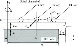
Figure 2 presents the simulation model for calculating the transport of the magnetic particles in the fluid suspension under the magnetic field produced by the HTS bulk magnet. The narrow separation channel in spiral form of n turns is placed in the open gradient magnetic field produced by the HTS bulk magnet. In the following analysis, we use a cylindrical coordinate system (r, θ, z) whose z-axis coincides with the center axis of the HTS bulk. The suspension with the magnetic particles flows along the spiral channel. In figure 2, 2dB and rB are the thickness and radius of the disk-shaped HTS bulk, respectively; dvac is the distance between the bulk surface and the cryostat surface; rc is the radius of the channel; ri and z0 are the position of the center of the ith turn channel. The inlet of the suspended particles is at θ=0 (the beginning of the 1st turn) and the outlet is at θ=2nπ (the end of the nth turn). We assume a laminar suspension flow in the channel.
Figure 2.

Simulation model.
The magnetic force  acting on the spherical particle in the suspension is expressed as [6]
where χp and χf are the magnetic susceptibilities of the particle and dispersed medium, respectively, Vp is the volume of a particle and μ0 is the vacuum permeability; B is the magnetic field produced by the HTS bulk magnet.
The particle concentration C(r, θ, z, t) (volume fraction) in the channel can be calculated using the following three-dimensional differential equation of the mass conservation:
Here J is the vector of the particle flux, t is the elapsed time, v is the drift velocity of the particle, k is the Boltzmann constant, T is the absolute temperature, η is the viscosity of the suspension and rp is the particle radius. The particle drift velocity v=(vr, vθ, vz) is expressed as [6]
Here vf is the flow velocity of the suspension along the channel whose maximum is vf,max; Fm, r and Fm, z are, respectively, the r and z components of  .
.
Boundary condition
Here we investigate the separation characteristics of the two kinds of particles with different magnetic susceptibilities. The particles A and B are the strong and weak magnetic particles, respectively, having magnetic susceptibilities χpA and χpB and the same radius. The mixed suspension of the particles A and B in pure water is injected from the area where 0⩽{(r−r0)2+(z−z0)2}1/2⩽rc,in (rc,in=rc/2 in this analysis) at θ=0 and time of t0, and the particles do not flow through the channel walls. Therefore, the following boundary conditions must be satisfied:
 |
Here CA and CB are the concentrations of the particles A and B, respectively, C0 is the initial particle concentration of both particles; t0 is determined assuming that t0×vf,max is constant.
The following parameter α is defined to evaluate the separation ability.
where MA,out and MB,out are the total amounts of particles A and B, respectively; α is calculated when all particles B come out from the outlet.
Results and discussion
Calculation parameter
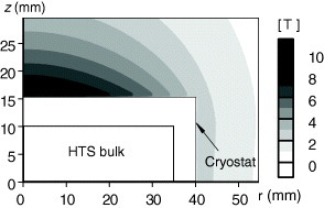
The calculation parameters are listed in table 1. Before analyzing the particle transport processes, we numerically calculated the magnetic field distribution around the HTS bulk magnet. In [7], it has been demonstrated that the HTS bulk can trap the magnetic field over 10 T when using the carbon fiber/resin impregnation, low melting temperature metal array and Al wire. Therefore, in this analysis, we set that the critical current density of the HTS bulk as 1×10⁹ A m−2. It is considered that the operation temperature of the HTS bulk magnet is 30 K corresponding to a 50 W/80 K class GM cryocooler. Figure 3 shows the magnetic field distribution in the area r≽rB+dvac and z≽dB+dvac (i.e. outside of the cryostat).
Table 1.
Calculation parameters
| r1 (mm) | 24.5 |
| z0 (mm) | 15.25–16.25 (i.e. dB+dvac+rc) |
| rc (mm) | 0.25–1.0 |
| n | 5 |
| vf,max(mm s−1) | 0.1–50 |
| 2dB (mm) | 20 |
| rB (mm) | 35 |
| dvac (mm) | 5 |
| χpA | 2×10⁻³–10−1 |
| χpB | 1×10⁻³ |
| rp (nm) | 5, 10, 25 |
| k | 1.38×10⁻²³ |
| T(K) | 300 |
| χf(H2O) | −9.05×10⁻⁶ |
| η(H2O) (g m−1) | 1.0 |
Figure 3.

Distribution of magnetic field generated by HTS bulk magnet.
Separation characteristics
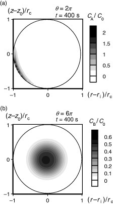
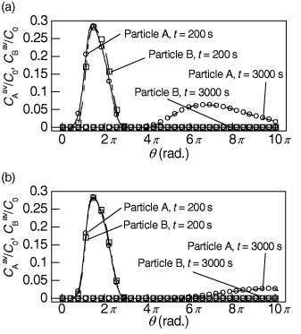
Figure 4 presents examples of the particle concentration profiles in the separation channel for rc=0.5 mm, rp=10 nm, vf,max=1 mm s−1 and t=400 s. The density of gray color represents the particle concentration normalized by the initial concentration C0. The strong (χpA=2×10⁻²) and weak (χpB=10−3) magnetic particles are injected from θ=0 of the first turn at t=0 s at time t0=100 s. Figure 4(a) presents the concentration profile of the particle A at θ=2π, and figure 4(b) shows that of the particle B at θ=6π. Figure 4(a) demonstrates that the particles with large magnetic susceptibility (particle A) clearly concentrate around the channel wall by the drift due to the magnetic force. On the other hand, figure 4(b) reveals that the weak magnetic particles (particle B) almost pass through without trapping. To better understand the separation processes, we normalized by C0 the average concentration profiles in the cross section of the separation channel of the particles A and B, CAav(θ,t)/C0 and CBav(θ,t)/C0, obtained from the calculated CA and CB, as shown in figure 5 for rp=10 nm, χpA/χpB=10, 20 and vf,max=1 mm s−1. A clear difference between the distributions of CAav and CBav along the separation channel is generated after 3000 s in figure 5(a). In this case, most of the strong magnetic particles are retained in the separation channel for a longer time than most of the weak magnetic particles. In contrast, from figure 5(b), no clear difference is observed between the particle concentrations, and the particles A and B cannot be effectively separated from each other in this case.
Figure 4.

Concentration distribution in channel. (a) Particle A: χpA=2×10⁻², rp=10 nm; (b) Particle B: χpB=1×10⁻³, rp=10 nm.
Figure 5.

Particle concentration averaged in channel cross section. (a) vf,max=1 mm s−1, rp=10 nm, χPA/χPB=20; (b) vf,max=1 μm s−1, rp=10 nm, χPA/χPB=10.
From the above results, it is considered that the separation characteristics can be analyzed by calculating the time evolution of the particle concentration. Figure 6 shows the dependences of α on vf,max and χpA/χpB for rp=5, 10 and 25 nm. Figure 7 presents the dependence of α on rc and χpA/χpB for vf,max=1 mm s−1. These figures reveal that α increases with decreasing vf,max and rc for same χpA/χpB. The reason why α at rc=0.25 mm is slightly smaller than those at rc=0.4 mm (figure 7(a)) is not clear at present, but it may be due to discretization errors in the numerical simulation. Therefore, the reduction in rc and vf,max is very effective to separate the two kinds of particle with the small χpA/χpB. Since the particle drift across the cross section of the channel is determined by Fm, η and rp, which is basically independent of vf,max, more particles can concentrate around the channel wall until they reach the outlet of the channel by reducing vf,max. Similarly, the necessary time that the particles move from the region around the channel center to the region near the channel wall shortens with decreasing rc. As results of the reduction in rc and vf,max, there is an increase in the difference in the particle concentration distribution in the separation channel. However, the reduction in vf,z,max and rc reduces the total processing amount. It should be noted that these parameters should be carefully designed corresponding to χpA/χpB and rp.
Figure 6.

Dependence of separation ability on flow velocity. (a) rp=5 nm; (b) rp=10 nm and rp=25 nm.
Figure 7.

Dependence of separation ability on channel radius. (a) rp=5 nm; (b) rp=10 nm and (c) rp=25 nm.
Concluding remarks
We investigated numerically the open gradient magnetic chromatography using an HTS bulk magnet and its applicability to the separation of particles having different magnetic natures. Our simulations showed that two kinds of particles with rp=10 nm, and χpA/χpB = 20 (χpB=10−3) could be sufficiently separated. This result suggests that the magnetic chromatography using the HTS bulk magnet can be applied to the separation of very fine paramagnetic particles such as insoluble elements in the nuclear fuel processing.
References
- Ohara T, Mori S, Oda Y, Wada Y. and Tsukamoto O. Trans. IEEEJ. 1996;116-B:979. [Google Scholar]
- Fukui S, Nakajima H, Ozone A, Hayatsu M, Yamaguchi M, Sato T, Imaizumi H, Nishijima S. and Watanabe T. IEEE Trans. Appl. Supercond. 2001;12:959. doi: 10.1109/TASC.2002.1018559. [DOI] [Google Scholar]
- Fukui S, Takahashi M, Fujita T, Yamaguchi M, Sato T, Imaizumi H, Oizumi M, Nishijima S. and Watanabe T. IEEE Trans. Appl. Supercond. 2004;14:1572. doi: 10.1109/TASC.2004.830711. [DOI] [Google Scholar]
- Takahashi M, Umeki T, Fukui S, Ogawa J, Yamaguchi M, Sato T, Imaizumi H, Oizumi M, Nishijima S. and Watanabe T. IEEE Trans. Appl. Supercond. 2005;15:2340. doi: 10.1109/TASC.2005.849661. [DOI] [Google Scholar]
- Takahashi M, Fukui S, Takahashi Y, Abe R, Ogawa J, Yamaguchi M, Sato T, Imaizumi H. and Ohara T. IEEE Trans. Appl. Supercond. 2006;16:1116. doi: 10.1109/TASC.2006.871336. [DOI] [Google Scholar]
- Ohara T. IEEE Trans. Magn. 1984;20:436. doi: 10.1109/TMAG.1984.1063068. [DOI] [Google Scholar]
- Tomita M. and Murakami M. Nature. 2003;421:517. doi: 10.1038/nature01350. [DOI] [PubMed] [Google Scholar]


