Abstract
For automation of biological experiments at the micro-scale, highly precise manipulator equipped with a microscope is required. However, current micropositioning stages have several limitations, such as: 1) manual operation, 2) lack of rotational capability, 3) incompatibility with a microscope, and 4) small range of motion (RoM). This research aims to develop a microscope compatible XYθ micropositioning stage with large RoM for phenotyping multiple biological samples rapidly for various microscopic applications. An underactuated planar mechanism, kinematic analysis, and control of the XYθ stage are presented in this paper. The planar mechanism consists of two piezoelectric linear actuators for translational motion capability and two passive revolute joints at the tip of each linear actuator for rotational capability. Based on the kinematic analysis of the stage, controllability and control strategy of the underactuated stage is described. Finally, the feasibility of the micropositioning stage for a general positioning and orienting task is verified by both simulation and tissue core experiments.
Keywords: Underactuated planar mechanism, Micropositioning, Controllability, Point-to-point control, Microscopic applications
I. Introduction
Since micropositioning techniques are essential for various scientific and engineering studies dealing with manipulation at the micro-scale (such as precise manufacturing or optical/chemical/biological applications), highly precise planar stages have been widely researched and developed in both academia and industry [1], [2]. Though several micropositioning stages exist, they have several drawbacks. Many of current stages are manually operated or incompatible with a microscope, while others allow translational motions only without rotational capability [3]–[5]. The rotational capability enables to phenotype a tissue sample more accurately by matching the coordinates of the sample through the microscopic image to the pathological region of interest. Most automated micropositioning stages have adopted piezoelectric actuator due to its advantages of high spatial resolution and high energy density that allows the system to be miniaturized [6]. A small range of motion (RoM) and slow movement speed, which are inherent of piezoelectric actuators, are other drawbacks of current micropositioning stages [1], [2]. For example, one of the representative and commercially available XYθ micropositioning stages, M-880 3-degrees of freedom (DoF) planar precision positioning system (Physik Instremente, Germany), has the RoM of ±10 mm in the X and Y axis with minimum incremental motion of 0.75 μm and ±4° in the rotation [7]. RoM of stages for ultra-precision application is even smaller mainly due to a trade-off between RoM and resolution. In the work of [8], “large travel ultra-precision XYθ stage” has the RoM of 3 mm × 3 mm for XY motion and less than 1° rotational motion, while its spatial resolution is less than 10 nm. Nowadays, however, piezoelectric actuators with large RoM are commercially available by increasing the RoM of the actuators [9], [10]. Since, current micropositioning stages are not suitable for our targeted application, which is automated tissue indentation, our research is motivated by the need for developing a customized micropositioning stage which has large RoM along with rotational capability.
An underactuated mechanism enables not only to make a system more compact and efficient, but it also helps to reduce the cost for building such a system by eliminating some actuators and several parts for the assembly [11]. However, the control problem for an underactuated system is challenging, since there is no general law applicable to any arbitrary under-actuated system [12]. Lynch [13] has shown that underactuated planar body with unilateral thrusters is controllable based on Sussmann's sufficient condition of local controllability [14]. Similarly, Li has shown that the dynamic model of a planar body is also small-time locally controllable by two pushing inputs [15].
Control for an underactuated system along a desired trajectory is realized by either modifying path planners for fully actuated systems such as the time-scaling algorithm [16], the decoupled approach to trajectory planning [17], passive velocity field control [18], or applying a customized control law for the specific system [19], [20]. Lynch and Bullo developed the path planner between two zero velocity states using decoupling velocity vector fields for kinematically controllable underactuated systems [21], [22]. Narikiyo proposed control strategies for several underactuated systems based on passive velocity field control [23]. However, the studies based on decoupling velocity vector fields are not applicable to all underactuated systems and often require cumbersome computation.
Motivated by previous studies for the controllability of a planar body with linear inputs, we have investigated an underactuated planar stage actuated by two piezoelectric linear actuators to develop an XYθ micropositioning platform. In addition, we propose sliding-mode control for point-to-point motion using the kinematic model. We conduct both simulation and tissue core experiments to verify the micropositioning performance of the platform.
II. Underactuated planar mechanism
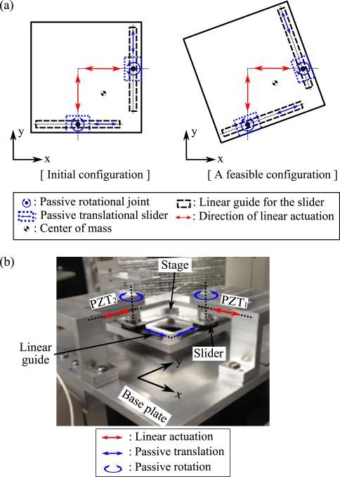
Although there are three types of planar mechanisms (serial, parallel, and hybrid) for micropositioning stages, parallel mechanisms are widely used due to several advantages, namely: 1) high accuracy (errors are not accumulated through the kinematic chain), 2) high structural stiffness, and 3) low inertia [24], [25]). As a result, we have designed our system as a parallel mechanism as shown in Fig. 1(a). The key feature of the mechanism is passive rotational joints added to orthogonal linear XY stage at idealized points of contact of PZT actuators with the stage. If the net line of force exerted on the body does not pass through the center of mass, the net force generates linear and rotational motion of the body simultaneously. In addition to this basic physics, motion constraints are imposed by two linear guides orthogonal each other and passive rotational joints on the actuation points allowing the body to move and rotate only along the guides.
Fig. 1.
(a) Schematic of the underactuated planar mechanism (scaled drawing) and (b) the manufactured platform.
The platform consists of three major layers in the longitudinal direction: 1) base plate, 2) moving stage, and 3) brackets with actuators. The base plate is fixed to a microscope and provides a planar working space for the moving stage. The moving stage has two linear guides that are perpendicular to each other, and is actuated by two piezoelectric linear actuators (SLC-2490-S, SmarAct, Germany) combined with 1 nm resolution position sensor. The slider on each linear guide is attached to the actuator. The rotational bearing between the slider and the actuator allows passive rotation of the stage relative to the fixed base plate.
The manufactured platform is shown in Fig. 1(b). Actual size of the stage is 112×112 mm2 with 85 mm length of the linear guide. The linear actuator is capable of 63mm stroke, which is determined as the target RoM to scan a whole standard glass slide. There is a hole at the center of the stage and the base plate for light to pass through, to obtain microscopic images. Low profile design is also important in a microscope compatible platform, due to the limited focal length of the microscope. More details regarding the design of the platform are described in our previous work [26].
III. Kinematic Analysis
A. Geometric Constraints
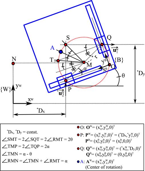
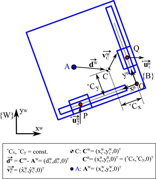
Since the rotational motion of the stage is constrained by two linear guides, the center of rotation (CoR) of the stage does not necessarily coincide with its geometric center or the center-of-mass (CoM). Moreover, it can be observed that the stage rotates with different radii in different configurations. Hence, the CoR is not a fixed point when the stage moves. The geometric relations for the stage including the CoR are shown in Fig. 2. The circle with the diameter of , which is the distance between two actuator tips, can be defined at every configuration as drawn by red dotted line in Fig. 2. The point O and the origin of body frame {B}, is on the circle due to the right angle of POQ. Similarly, the two points, S and T, which is the intersection point of the extension lines from each actuator in parallel with the world frame coordinates and the body frame coordinates, respectively, are on the circle as well. Since the angle subtended at the center is twice the angle at the circumference, (or ) must be the same as the stage angle θ.
Fig. 2.
Schematic of the geometric relations and the coordinate system of the stage (scaled drawing). {W}, {B}, and is the world frame (fixed frame), the body frame (moving frame), and the input velocity vector of linear actuators in xW and yW direction, respectively. The parameters denoted by * represent the known values due to the structure or measurements.
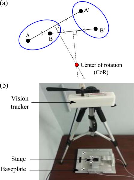
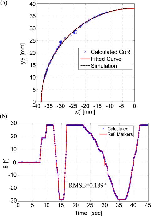
When a rigid body rotates about a fixed point, the CoR is geometrically determined by the intersection point between two perpendicular bisectors of two points on the body as shown in Fig. 3(a). Therefore, we can find the CoR of the stage as the point A, which is the intersection point between the angular bisector of and the circle with diameter , and the CoR moves along the circle when the stage rotates. To visualize and verify instantaneous CoR of the stage, a vision tracking experiment was conducted with four markers as shown in Fig. 3(b). Two markers on the stage are for calculating the instantaneous CoR points while the stage is manually rotated with fixed actuators. The other two markers on the base plate are for a reference line so that we can calculate the rotational angle of the stage. Calculated CoR coordinates in {W} frame obtained from the vision tracking data are shown in Fig. 4(a) along with the simulated CoR trajectory, which is the circle with diameter, . In this plot, the origin of the {W} frame is placed on the point M, which is the midpoint of , for ease of understanding. Therefore, the simulation result represents the equation of: . Unless angle θ is close to zero, the CoR of the stage moves along the circle made by the geometric constraints as predicted. The instability near zero degrees is due to the low resolution of the vision tracker and singularity in the analytical model. Figure 4(b) shows the similarity between the rotational angle calculated from instantaneous CoR and the measured angle from the markers with root-mean-square-error of 0.189°. Moreover, the angular RoM of the stage can be found to be [−28.5°, 2.5°].
Fig. 3.
Experimental setup for finding instantaneous CoR of the stage: (a) schematic of geometrically defined CoR and (b) the experimental setup.
Fig. 4.
Results of the vision tracking experiment to find the instantaneous CoR: (a) the coordinates of instantaneous CoR, and (b) comparison of the measured angle of the stage with the calculated angle from instantaneous CoR.
B. Kinematic Modeling
To derive the kinematic model of the stage, the two coordinate systems, namely, the world frame, {W} (fixed frame), and the body frame, {B} (moving frame), are defined and shown in Fig. 2 The origin of the body frame {B} is placed at the intersection point of two linear guides. The direction of xB-axis is opposite to the direction of xW-axis at the initial configuration so that all variables in {B} can be defined as positive values. Since the coordinate system of the microscopic image is fixed, the kinematic model should be interpreted in the fixed frame {W} for ease of matching these two coordinate systems. The rotation matrix from the body frame {B} to the world frame {W}, , and its time derivative, , can be expressed as:
| (1) |
where, Sθ = sinθ and Cθ = cosθ.
Since the linear actuators are aligned along the respective axes in {W}, the velocity input vector of each linear actuator has only one non-zero component. Thus:
| (2) |
The velocity of point Q is and that of point P is . The position and velocity of point Q in {W} can be written as:
| (3) |
| (4) |
Since the stage is a rigid body, the position and velocity at any point on the stage can be described in the same way. By re-arranging the equations of position and velocity of the point P and Q, the velocity of point O in {W} can be described as:
| (5) |
where, , , and Tθ = tanθ, while Dx and Dy are the distance of point P along xW-axis and the distance of point Q along the yW-axis from the origin of {W} respectively.
Now, we apply angular momentum equation to derive the state differential equation of the stage by formulating an independent equation for as a function of the state variables and the control inputs only. As long as the rotational axis is parallel to the principal Z-axis of the moment of inertia, angular momentum of the body in XY plane can be treated as a scalar. Figure 5 represents a schematic diagram for calculating angular momentum of the stage. L, the angular momentum of the stage is given by:
| (6) |
where, dW is the moment arm vector, m is the mass of the stage, the linear velocity vector at the CoM, and IC is the moment of inertia at the CoM.
Fig. 5.
Schematic of the angular momentum of the stage (scaled drawing).
To solve for from the angular momentum equation, dW and need to be expressed as functions of the state variables, , and the control inputs explicitly. Since the CoM is also on the stage, its position CW and velocity in {W} can be expressed as:
| (7) |
where, CB = [Cx, Cy, 0]T.
| (8) |
From the geometric constraint of , the expression for the CoR position contains α as well. Consequently, the moment arm vector, dW, is derived as:
| (9) |
where, , , Sα = sinα, Cα = cosα, and .
By substituting dW and into Eq. (6), can be expressed as:
| (10) |
where, , , , S(α+θ) = sin(α + θ), and C(α+θ) = cos(α+θ).
Since is a function of α as well, it is required to express as a function of the state variables and control inputs. From geometry, we can derive:
| (11) |
By differentiating Eq. (11), we get:
| (12) |
The state differential equation of the stage with the state vector can be expressed as:
| (13) |
C. Controllability
When we consider a nonlinear system, Φ, without drift, the general model of the system is given by:
| (14) |
where, is the n-dimensional state vector of the system, is the m-dimensional system input vector, and gj (j = 1, ··· , m) are smooth, linearly independent vector fields on defined for all time, t [27].
Using Chow's theorem [27], we find the rank of the involutive closure of Δ = span{g1, ··· , gm}. The involutive closure can be constructed by taking the Lie bracket between two vector fields in Δ [28]. The construction rule is given by:
| (15) |
where, [G1, Gi–1] = span{[f,g] : f ∈ G1, g ∈ Gi–1}. If rank[Gi–1] = rank[Gi], Gi becomes the involutive closure.
To check controllability of the stage, the state differential equation is rearranged as:
| (16) |
where,
Using G1 = span{g1, g2} as the initial distribution, we apply the construction rule until the resultant distribution does not gain any additional dimension. Thus, we get:
| (17) |
where, g3 = [g1, g2], g4 = [g1, [g1, g2]] = [g1, g3], and g5 = [g2, [g1, g2]] = [g2, g3].
The involutive closure has the same dimension as the dimension of the state space. Therefore, the underactuated stage using two linear actuators with passive revolute joints is locally controllable by Chow's theorem. It is important to note that when H = 0, g1 and g2 are undefined (note: , and YO > 0 by the structure). Theoretically, H = 0 occurs when the moment of inertia at the CoR coincides with the coefficient of from the angular momentum equation calculated by the linear momentum of the stage. This implies that the system is locally controllable at all times unless when H = 0. In our system, H cannot be equal to zero under the bounded parameters of Cx, Cy, and θ. Since the stage is symmetric about the line, in {B}, the CoM lies on the line and the relation, Cx = Cy holds. When we apply the conditions, , as shown in the “Geometric constraints” section), Cx = Cy, and they are both greater than zero, H is always greater than zero as shown below:
| (18) |
Since all the designed parameters of IC, m, Cx Cθ, XO, and YO are positive numbers, the denominator H is positive definite. Therefore, the current stage is locally controllable at all times.
IV. Point-to-point Control Strategy
A. Step 1: Rotation and finding the desired sliding line in XY plane under condition
For a single variable dynamic system with a state vector , we can replace the original nth-order tracking problem into a 1st-order stabilization problem in s by defining a time-varying sliding surface s as [29]:
| (19) |
where x̃ = xd – x is the tracking error and λ is a strictly positive constant.
When n = 1, the sliding surface for the rotation can be defined as s1 = eθ. Based on ṡ1 = 0, the input vector for the rotation, urot can be defined as:
| (20) |
where krot is a strictly positive control gain for the rotation, sgn(s1) is the signum function of a real number s1, and .
The tracking error of rotation converges to 0 as t → ∞ (i.e. globally asymptotically stable) by Lyapunov stability theorem with a choice of positive definite Lyapunov function, as shown below:
| (21) |
Once the stage reaches the desired orientation, we impose the motion constraint , allowing the two inputs to be related by . Thus, the stage always keeps its desired orientation until it reaches the desired position. The trajectory of point O under the motion constraint of is determined by the ratio of to as:
| (22) |
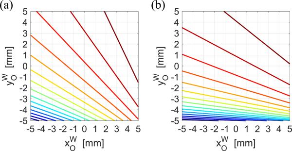
Due to the imposed motion constraint of , Jc should be a straight line and the slope of the line is determined by and q as shown in Fig. 6. This implies that pure translational motion of the stage can be achieved between two points having the same value of Jc. Without loss of generality, we can find Jd, which is Jc at the desired state, as:
| (23) |
where (Ki)d = (Ki)X=Xd for i = 1, 2.
Fig. 6.
Examples of the contour plot for under the motion constraint of (a) with θ = 0° and (b) with θ = 10°.
The desired sliding line in XY plane that consists of a set of points can be defined as:
| (24) |
where a is the slope of the sliding line.
B. Step 2: Reaching the sliding line
Let be the sliding surface to reach the desired line found in Step 1). By setting ṡ2 = 0, we can define the inputs for reaching the desired sliding line as:
| (25) |
where ksld is a strictly positive control gain for reaching the sliding line and .
While usld1 is attracting the states towards the desired sliding line, usld2 tries to keep its orientation from uncertainties such as unmodeled dynamics and kinematic modeling errors. usld satisfies globally asymptotically stable condition of Lyapunov stability theorem with a positive definite Lyapunov function, , under the motion constraint of . V̇2 can be expressed as:
| (26) |
C. Step 3: Translation to the desired position along the sliding line
To reach the desired position along the sliding line, let be the sliding surface. When ṡ3 = 0, we can satisfy globally asymptotically stable condition of Lyapunov theorem by defining the inputs as:
| (27) |
where ktrl is a strictly positive control gain for the translational motion along the sliding line and .
utrl2 maintains the orientation and keeps adjusting the states to stay on the sliding line while utrl1 tracks the desired x coordinate. The control inputs guarantees the stability of the system and the convergence of s3 to zero with a positive definite Lyapunov function, . V̇3 can be expressed as:
| (28) |
D. Simulation
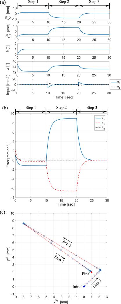
Since α is computed at every time step from the state differential equation (Eq. (13)) and we are not controlling α directly, let and be the initial and desired position and orientation of the stage for the simulation, respectively. Initially, the origin of the fixed frame, {W}, coincides with the origin of the moving frame, {B} and α0 is determined as 45° by substituting , , Dx = −47.5mm, and Dy = 47.5mm in Eq. (11). The moment of inertia at CoM and the coordinates of CoM point in {B} were determined by 3D modeling as Ic = 297.57kg mm2 and CB = [Cx, Cy, 0]T = [39.21mm, 39.21mm, 0]T, respectively. The slope of the sliding line was determined as a = −0.7414 from the contour plot for Jc. The control gains, (krot,ksld,ktrl) = (0.001+120|s1|,0.001+10s2,0.001+ |s3|), were used in the simulation. Since the stage is controlled by velocity inputs, reducing inherent chattering effect and smoothing the inputs are important for stable manipulation. Instead of using constant control gains, each control gain was determined by the summation of a small positive constant gain and a gain proportional to the absolute error. Using this approach, we are able to smoothly control and achieve good control performance at both millimeter-scale and micro-scale. The maximum speed and maximum stroke of the actuator did not violate the physical limitations during the simulation by choosing proper control gains.
Figure 7(a) shows the state variables and the input during the simulation. By applying the control strategy, the errors of position and orientation of the stage converge to zero as shown in Fig. 7(b). The trace of the coordinates () during the simulation is shown in Fig. 7(c), where we track how the stage has moved according to each step of the control strategy.
Fig. 7.
Simulation results of proposed point-to-point control strategy for (a) the state variables and the inputs, (b) the tracking errors (i.e. ex, ey, and eq), and (c) the trace of the coordinates .
V. Experiments and Discussion
In practical application with a microscope, the position and orientation of a sample (which can be arbitrary within the range of motion of the system) should be tracked, instead of the point OW. Since the stage is a rigid body, the coordinates of a sample on the stage can be represented in the fixed frame {W} once the coordinates of the sample are given in the moving frame {B} as:
| (29) |
where [xW, yW, 0]T and [xB, yB, 0]T are the coordinates of a sample on the stage represented in the fixed frame {W} the moving frame {B}, respectively.
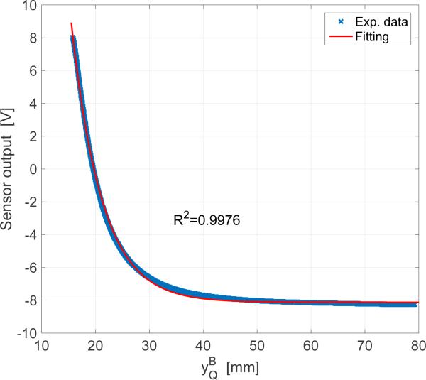
Measuring the orientation for the stage is challenging for two reasons; 1) the position of the stage cannot be obtained unless the orientation is known and 2) the relative angle between the base plate and the moving stage should be measured under the limited space. An encoder, one of the most common sensors for measuring the angle, is not applicable to the stage due to varying center of rotation and an external vision system with markers has too low resolution and requires wider space as shown in Section II. Since the orientation of the stage can be obtained by measuring either or from the geometry (See Table 1), a fiber-optic sensor was chosen as a feasible option. Through the comparison of two cases, which are measuring both and directly by two fiber-optic sensors and using the trigonometry, , with measuring , the latter showed better control performance mainly due to much higher precision on the measurement of by the nanometer resolution PZT positioner. To realize a feedback control system, an additional fiber-optic sensor (FU-77, Keyence, Japan) with amplifier (FS-V31, Keyence, Japan) was implemented on the stage to measure , the distance, . Figure 8 shows the calibration result of the fiber-optic sensor and the exponential curve fitting (, where [p1, p2, p3, p4]T = [204.2, −0.1763, 0.25, −8.126]T) with R2-value of 0.9978. Instead of using the one-to-one exponential function, we used a lookup table consisting of the calibration data for the actual experiments to achieve higher accuracy. The PZT2 sweeps the full range of motion at a speed of 10 μm/s, while the passive rotational joints are locked to prevent the stage from rotating. By measuring the positions of the two actuators (i.e. and ) and the stage becomes a fully observable system by determining all the state variables of as shown in Table I.
TABLE I.
Observation of the state variables
| Variables | Definition |
|---|---|
| r | |
| α | |
| θ | |
Fig. 8.
Fiber-optic sensor calibration result.
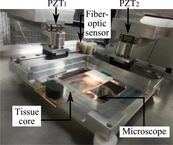
Figure 9 shows the experimental setup for tracking a tissue core sample of 600 μm diameter on a glass slide. Current control hardware system includes the Modular Control System (MCS, SmarAct, Germany) as the controller specialized for the PZT actuators and data acquisition board (Model 626, Sensoray, USA) which contains 16-bits analog-to-digital converter for reading the output of the fiber-optic sensor. C++ language is used as a compiler for implementation of the control algorithm and update rate of the control action is set to 100 Hz, which comes from the maximum reliable update rate of the PZT position sensors.
Fig. 9.
Experimental setup for point-to-point control.
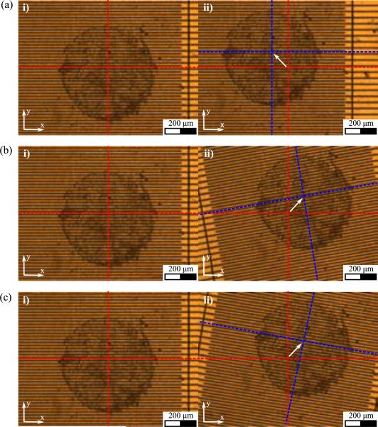
The target task of this experiment is to move the tissue core from the initial position and orientation to desired position and orientation by the proposed control scheme. Comparison of microscopic images before and after the task is used as an auxiliary tool to evaluate the control performance. The center point of the stage is tracked throughout the experiments. At the initial state, it corresponds to the center of the microscopic image. Three test cases were conducted to verify the control performance of the system:
Experiment (1): [xd, yd, θd]T = [−100μm, 100μm, 0°]T (translation)
Experiment (2): [xd, yd, θd]T = [100μm, 100μm, 10°]T (maximum rotation in counter-clockwise direction with the desired position and orientation)
Experiment (3): [xd, yd, θd]T = [100μm, 100μm, 10°]T (maximum rotation in clockwise direction with the desired position and orientation)
The desired position and orientation of Experiment (1) can be achieved by applying only ‘step 3’ of the control strategy, since the initial position of the stage lies on the desired sliding line with the desired orientation already, while Experiment (2) and Experiment (3) require all steps of the control strategy.
The experimental results of the proposed point-to-point control after 5 trials of each case are presented in Table II. The micropositioning platform shows sub-micron accuracy and repeatability both in measurement and image analysis. Tissue core images at the initial and final state of each case are shown in Fig. 10. Figure 11 shows the actual trace of the tissue sample for each case. Since the control law is based on the kinematic model of the system, rotation occurs during the motion under the constraint due to the inherent dynamics of the actuators and friction between the stage and the base plate. However, the corrective control actions compensate the errors and ensure that the state converges to the desired state. The errors of the state variables and the control inputs during the experiments are shown in Fig. 12.
TABLE II.
Experimental results of point-to-point control
| x (μm) | y (μm) | θ (°) | ||
|---|---|---|---|---|
| Exp. (1) | D | −100.00 | 100.00 | 0.00 |
| M | −99.91 ± 0.23 | 99.97 ± 0.29 | 0.01 ± 0.01 | |
| I | −100.22 ± 0.42 | 100.16 ± 0.48 | 0.01 ± 0.01 | |
| Exp. (2) | D | 100.00 | 100.00 | 10.00 |
| M | 100.21 ± 0.43 | 100.37 ± 0.39 | 10.01 ± 0.02 | |
| I | 101.09 ± 0.82 | 100.97 ± 0.80 | 9.98 ± 0.07 | |
| Exp. (3) | D | 100.00 | 100.00 | −10.00 |
| M | 99.88 ± 0.53 | 100.33 ± 0.43 | −10.01 ± 0.01 | |
| I | 100.92 ± 0.79 | 100.38 ± 0.77 | −10.04 ± 0.05 | |
D: Desired, M: Measured, I: Image analysis
Fig. 10.
Tissue core images at the initial and final position (x,y) and orientation θ (a) Experiment (1): [xd, yd, θd]T = [−100μm, 100μm, 0°]T, (b) Experiment (2): [xd, yd, θd]T, = [100μm, 100μm, 10°]T, and (c) Experiment (3): [xd, yd, θd]T = [100μm, 100μm, −10°]T. Red and blue dotted lines represent the central lines of the stage at the initial and final state, respectively. Note: αd is determined from the desired position and orientation using Eq. (11).
Fig. 11.
Trace of the tissue core sample (a) Experiment (1): [xd,yd,θd]T = [−100μm, 100μm, 0°]T, (b) Experiment (2): [xd,yd,θd]T = [100μm, 100μm, 10°]T, and (c) Experiment (3): [xd,yd,θd]T = [100μm, 100μm, −10°]T. Note: αd is determined from the desired position and orientation using Eq. (11).
Fig. 12.
Tracking errors and control inputs (a) Experiment (1): [xd,yd,θd]T = [−100μm, 100μm,0°]T, (b) Experiment (2): [xd,yd, θd]T = [100μm, 100μm,10°]T, and (c) Experiment (3): [xd,yd,θd]T = [100μm, 100μm, −10°]T. Note: αd is determined from the desired position and orientation using Eq. (11).
The workspace of the stage in XY plane varies with the desired angle. Theoretically, the stage can sweep 63 mm × 63 mm, whole range of actuators’ stroke at the zero degrees. However, RoM in the XY plane at ±10°, the maximum/minimum angle in the current design, shrinks to 32 mm × 32 mm. Therefore, the practical workspace of the stage can be determined conservatively as (x, y, θ) = (32 mm, 32 mm, 20°). However, the stage cannot reach angles greater than ±10° in the current design. The theoretical range of angle, [−28:5°, 28:5°], was measured under the condition that the stage is manually rotated by an external force, not by the system inputs, to verify the geometric constraints. In the theoretical case, the entire range of linear guide can be utilized for rotational motion only, while the linear PZT actuations contribute to the linear and rotational motion of the stage simultaneously. Moreover, the proposed control law requires a longer travel distance to reach the sliding line for the larger desired angle. Therefore, the slider on the linear guide reaches at the end of the linear guide before reaching maximum theoretical angle when the stage is rotated by the linear PZT actuators under the proposed control scheme. It is also important to note that the cables of the fiber-optic sensor introduce disturbances into the system that the controller cannot compensate by physically touching the brackets (the structure fixing the PZT actuator). At larger angles, the cables bounce back due to interference with the motion of the stage. The maximum angle of the stage can be increased by implementing a more elaborate control law with optimal path planning and solving the cable routing problem.
VI. Conclusion
An underactuated mechanism of XYθ micropositioning stage using two linear PZT actuators, its kinematic analysis, and point-to-point control strategy were investigated. Though the control law we proposed is based on the kinematic model of the stage, the system appears to be robust from dynamic uncertainties in the experiments. The underactuated stage has to undergo larger travel distance along with a less intuitive path to reach the desired state than a fully-actuated stage. However, the simulation and experiments with the proposed control strategy have shown promising results to be implemented in biomedical applications that require microscope compatible micropositioning platform. Besides several advantages of an underactuated system, enlarging RoM for a micropositioning stage with sub-micron accuracy is a meaningful result for the automation of phenotyping multiple biological samples. In our future work, we plan to perform automated tissue indentation experiments with a 4-DoF indentation system (the XYθ stage with additional Z-directional indenter) to verify the feasibility of the automated process.
Acknowledgment
Research reported in this publication was supported by the National Cancer Institute of the National Institutes of Health under Award Number R01CA161375. The content is solely the responsibility of the authors and does not necessarily represent the official views of the National Institutes of Health.
The authors would also like to thank Ms. Carolyn M. Davis for designing and developing the micropositioning stage and Dr. Hardik J. Pandya for developing the microgrid.
Biography
 Kihan Park (S'15) received the B.S., M.S degrees in mechanical engineering from Korea Advanced Institute of Science and Technology (KAIST), Daejeon, South Korea, in 2009 and 2011, respectively. He is currently working toward the Ph.D degrees in mechanical engineering at the University of Maryland, College Park, MD, USA. His research interests include medical robotics and tissue characterization for cancer diagnosis.
 Jaydev P. Desai (SM'04) is currently a Professor in the Department of Mechanical Engineering and a Member of the Maryland Robotics Center at the University of Maryland, College Park (UMCP). Prior to joining UMCP, he was an Associate Professor at Drexel University, Philadelphia, PA, USA. He completed his undergraduate studies from the Indian Institute of Technology, Bombay, India, in 1993. He received his M.A. in Mathematics in 1997, M.S. and Ph.D. in Mechanical Engineering and Applied Mechanics in 1995 and 1998 respectively, all from the University of Pennsylvania. Prior to joining Drexel University, he was a Post-Doctoral Fellow in the Division of Engineering and Applied Sciences at Harvard University, Cambridge, MA, USA. He is a recipient several NIH R01 awards, NSF CAREER award, and was also the lead inventor on the Outstanding Invention of 2007 in Physical Science Category at the University of Maryland, College Park. He is also the recipient of the Ralph R. Teetor Educational Award. In 2011, he was an invited speaker at the National Academy of Sciences Distinctive Voices seminar series on the topic of Robot Assisted Neurosurgery at the Beckman Center, Irvine, CA, USA. He was also invited to attend the National Academy of Engineerings 2011 U.S. Frontiers of Engineering Symposium. His research interests include image-guided surgical robotics, reality-based soft-tissue modeling for surgical simulation, grasping, haptics, and micro-scale cell and tissue characterization. He is also a fellow of the American Society of Mechanical Engineers (ASME).
Appendix
Appendix.
Nomenclature and Definition
| Symbol | Definition | |
|---|---|---|
| {W} | World frame (or fixed frame) | |
| {B} | Body frame (or moving frame) | |
| θ | Orientation of the stage | |
| Angular velocity of the stage | ||
| Sθ | sinθ | |
| Cθ | cosθ | |
| Tθ | tanθ | |
| Rotation transformation matrix from {B} to {W} | ||
| Time derivative of | ||
| O | Origin of {B} | Ω |
| P | Idealized point of contact of PZT2 with the stage | |
| Q | Idealized point of contact of PZT1 with the stage | |
| M | Midpoint of | |
| A | CoR of the stage | |
| C | CoM of the stage | |
| ΩW | Position vector of Ω in {W} | |
| Velocity vector of Ω in {W} | ||
| ΩB | Position vector of Ω in {B} | |
| Velocity vector of Ω in {B} | ||
| α | Angle of ZQPO | |
| u1 | Linear input velocity by PZT1 along the xW-axis | |
| u2 | Linear input velocity by PZT2 along the yW-axis | |
| Velocity input vector by PZT1 in {W} | ||
| Velocity input vector by PZT2 in {W} | ||
| Dx | x-coordinate of the geometric center of the stage in {W} | |
| Dy | y-coordinate of the geometric center of the stage in {W} | |
| IC | Moment of inertia of the stage at the CoM | |
| m | Mass of the stage | |
| dw | Moment arm vector in {W} | |
| Velocity vector of the CoM in {W} | ||
| L | Angular momentum vector of the stage in {W} | |
| Cx | x-coordinate of the CoM of the stage in {B} | |
| Cy | y-coordinate of the CoM of the stage in {B} | |
| Jc | Ratio of to under the constraint of | |
| Jd | Value of Jc at the desired position and orientation | |
| xd | Desired x-coordinate position of the stage in {W} | |
| yd | Desired y-coordinate position of the stage in {W} | |
| θd | Desired orientation of the stage | |
| X | State vector of the stage | |
| Ẋ | Time derivative of X | |
| ex | Position tracking error along the xW axis | |
| ey | Position tracking error along the yW axis | |
| eθ | Orientation tracking error | |
References
- 1.Ouyang P, Tjiptoprodjo R, Zhang W, Yang G. Micro-motion Devices Technology: The State of Arts Review. The International Journal of Advanced Manufacturing Technology. 2008;38(5-6):463–478. [Google Scholar]
- 2.Yong YK, Lu T-F, Handley DC. Review of Circular Flexure Hinge Design Equations and Derivation of Empirical Formulations. Precision Engineering. 2008;32(2):63–70. [Google Scholar]
- 3.Li Y, Xu Q. A Novel Piezoactuated XY Stage with Parallel, Decoupled, and Stacked Flexure Structure for Micro-/Nanopositioning. Industrial Electronics, IEEE Transactions on. 2011;58(8):3601–3615. [Google Scholar]
- 4.Yong YK, Aphale SS, Moheimani SR. Design, Identification, and Control of a Flexure-based XY Stage for Fast Nanoscale Positioning. Nanotechnology, IEEE Transactions on. 2009;8(1):46–54. [Google Scholar]
- 5.Li Y, Huang J, Tang H. A Compliant Parallel XY Micromotion Stage with Complete Kinematic Decoupling. Automation Science and Engineering, IEEE Transactions on. 2012;9(3):538–553. [Google Scholar]
- 6.Arnold S, Pertsch P, Spanner K. Piezoelectricity: Evolution and Future of a Technology. Springer; 2008. Piezoelectric Positioning. [Google Scholar]
- 7.Instrumente P. 2014 complete precision positioning catalog PI & PI miCos. 2014 [Online]. Available: http://www.pi-usa.us/pdf/index.php.
- 8.Kuo S-K, Shan X, Menq C-H. Large Travel Ultra Precision x-y-q Motion Control of a Magnetic-suspension Stage. Mechatronics, IEEE/ASME Transactions on. 2003;8(3):334–341. [Google Scholar]
- 9.Xu Q. Design, Testing and Precision Control of a Novel Long-stroke Flexure Micropositioning System. Mechanism and Machine Theory. 2013;70:209–224. [Google Scholar]
- 10.Humphris A, Miles M, Hobbs J. A Mechanical Microscope: High-speed Atomic Force Microscopy. Applied Physics Letters. 2005;86(3):34, 106–34, 106. [Google Scholar]
- 11.Sun Z. First International Conference on Information Sciences, Machinery, Materials and Energy. Atlantis Press; 2015. Research on the Motion Control for the Underactuated Mechanical Systems; pp. 1928–1931. [Google Scholar]
- 12.Spong MW. Control Problems in Robotics and Automation. Springer; 1998. Underactuated Mechanical Systems. [Google Scholar]
- 13.Lynch KM. Controllability of a Planar Body with Unilateral Thrusters. Automatic Control, IEEE Transactions on. 1999;44(6):1206–1211. [Google Scholar]
- 14.Sussmann HJ. A Sufficient Condition for Local Controllability. SIAM Journal on Control and Optimization. 1978;16(5):790–802. [Google Scholar]
- 15.Li Q, Payandeh S. Modeling and Analysis of Dynamic Multi-agent Planar Manipulation. Proceedings of the 2001 IEEE International Symposium on Computational Intelligence in Robotics and Automation. 2001:200–205. [Google Scholar]
- 16.Bobrow JE, Dubowsky S, Gibson J. Time-optimal Control of Robotic Manipulators Along Specified Paths. The International Journal of Robotics Research. 1985;4(3):3–17. [Google Scholar]
- 17.Shiller Z, Dubowsky S. On Computing the Global Time-optimal Motions of Robotic Manipulators in the Presence of Obstacles. Robotics and Automation, IEEE Transactions on. 1991;7(6):785–797. [Google Scholar]
- 18.Li PY, Horowitz R. Passive Velocity Field Control of Mechanical Manipulators. Robotics and Automation, IEEE Transactions on. 1999;15(4):751–763. [Google Scholar]
- 19.Ortega R, Spong MW, Gómez-Estern F, Blankenstein G. Stabilization of a Class of Underactuated Mechanical Systems via Interconnection and Damping Assignment. Automatic Control, IEEE Transactions on. 2002;47(8):1218–1233. [Google Scholar]
- 20.Sankaranarayanan V, Mahindrakar AD. Control of a Class of Underactuated Mechanical Systems Using Sliding Modes. Robotics, IEEE Transactions on. 2009;25(2):459–467. [Google Scholar]
- 21.Lynch KM, Shiroma N, Arai H, Tanie K. Collision-free Trajectory Planning for a 3-DoF Robot with a Passive Joint. The International Journal of Robotics Research. 2000;19(12):1171–1184. [Google Scholar]
- 22.Bullo F, Lynch KM. Kinematic Controllability for Decoupled Trajectory Planning in Underactuated Mechanical Systems. Robotics and Automation, IEEE Transactions on. 2001;17(4):402–412. [Google Scholar]
- 23.Narikiyo T, Sahashi J, Misao K. Control of a Class of Underactuated Mechanical Systems. Nonlinear Analysis: Hybrid Systems. 2008;2(2):231–241. [Google Scholar]
- 24.Mejia L, Simas H, Martins D. Force Capability in General 3-DoF Planar Mechanisms. Mechanism and Machine Theory. 2015;91:120–134. [Google Scholar]
- 25.Yao Q, Dong J, Ferreira PM. Design, Analysis, Fabrication and Testing of a Parallel-kinematic Micropositioning XY Stage. International Journal of Machine Tools and Manufacture. 2007;47(6):946–961. [Google Scholar]
- 26.Davis CM, Park K, Desai JP. Design and Analysis of an Under-actuated XYq Stage for Automated Tissue Indentation. Proceedings of the 2015 IEEE/RSJ International Conference on Intelligent Robots and Systems. 2015:4331–4336. [Google Scholar]
- 27.Murray RM, Li Z, Sastry SS. A Mathematical Introduction to Robotic Manipulation. CRC press; 1994. [Google Scholar]
- 28.Murray RM, Sastry SS. Nonholonomic Motion Planning: Steering Using Sinusoids. Automatic Control, IEEE Transactions on. 1993;38(5):700–716. [Google Scholar]
- 29.Slotine J-JE, Li W. Applied Nonlinear Control. Prentice-hall Englewood Cliffs; NJ: 1991. [Google Scholar]


