

Abstract
The precise modification of redox species on the inner and outer surfaces of hollow nanostructures is relevant in catalysis, surface science, and nanotechnology, but has proven difficult to achieve. Herein, we develop a facile approach to specifically fabricate Pt and Co3O4 nanoparticles (NPs) onto the interior and exterior surface of hollow carbon nitride spheres (HCNS), respectively, to promote the surface redox functions of the polymer semiconductors. The photocatalytic water splitting activities of HCNS with spatially separated oxidation and reduction centers at their nanodomains were enhanced. The origin of the enhanced activity was attributed to the spatially separated reactive sites for the evolution of H2 and O2 and also to the unidirectional migration of the electron and hole on the Janus surfaces, thereby preventing the unwanted reverse reaction of water splitting and decreasing charge recombination.
Keywords: conjugated polymers, hollow structures, nanoparticles, supported catalysts, water splitting
The artificial photocatalytic system for splitting water into H2 and O2 using semiconductor materials has become a cutting‐edge research area, because of the growing interest in the clean and direct production of H2 from water utilizing abundant solar irradiation.1 Although considerable efforts have been made to develop efficient hybrid photocatalytic systems for water splitting, further improvements of the quantum efficiencies and the availability of visible light are necessary for their practical use, and natural photosynthetic structures are still offering blueprints for designing artificial photosynthesis systems.2 Biological systems have been structurally optimized to establish high quantum efficiencies in their excitation and electron transfer reactions during 3 billion years of evolution.3
In plants, photosynthesis occurs in the thylakoid membrane where functional proteins and electron carriers are precisely arranged to convert sunlight into a chemical potential between the sides of the membrane, via charge separation and electron transport chains, for use in oxygen generation and CO2 fixation.4 In the photosynthetic thylakoid membrane, both the water‐oxidation center (photosystem II) and the carbon dioxide‐reduction center (photosystem I) are incompatible and must be strictly separated in nanospace. Their placement on two sides of a membrane structure enables a local proton gradient to develop, which drives adenosine triphosphate synthesis via photoredox reactions.5 Examples of such soft hollow structures with the precise replacement of cofactors and from different materials are generally still rare. A hollow conjugated polymer nanosphere could be a practical alternative that enables the localization of redox active sites on the interior and exterior surfaces of the hollow structure for photocatalyzing the water splitting reaction. The differences in the non‐equilibrium free energy between the polymeric “membrane” can directionally drive the migration of electrons and holes to the inner and outer surfaces of reduction and oxidation sites, respectively, which facilitates the localization of charge, thereby decreasing recombination and prohibiting the reverse reaction of O2 and H2 on noble‐metal co‐catalysts to yield water.6
Many efforts have been made to fabricate core–shell photocatalysts to disconnect photooxidation and photoreduction centers for splitting water.7 Domen et al. demonstrated a proof‐of‐concept advance using a SiO2/Ta3N5 core/shell photocatalyst loaded with Pt NPs on the inner Ta3N5 shell surface, which acts as an electron collector, and IrO2 or CoOx on the outer shell surface, which acts as a hole collector.7a The core/shell of Ta3N5 was modified with separated dual cocatalysts, which significantly improved the photocatalytic activity for the evolution of H2 and O2. After the removal of the SiO2 template, the construction of the substrate cannot be well sustained as a hollow nanostructure, which is desired for promoting surface reactions after precise modifications. Indeed, hollow core–shell nanostructures have been introduced as promising functional architectures by Lou's group for a wide number of promising applications, such as batteries, supercapacitors, and electrochemistry.8 However, most of these hollow structures are inorganic substances and, thus far, the Janus modification of hollow photocatalysts is mostly limited to inorganic semiconductors, such as TiO2 and Ta3N5.9
Compared to inorganic semiconductors, soft hollow conjugated polymer spheres are more similar to biological membranes, but retain the added‐value of light‐harvesting functions and organic features for chemical modification.10 If well developed, hollow conjugated polymers are expected to act as an ideal host scaffold for assembling dual cocatalysts to create complex nanostructures for cascade catalysis by shuttling energy and charge transfer. The organic feature of the polymeric hollow structure could also enable further chemical modification of the reactive inner/outer surface. However, most hollow polymer nanospheres are typically undergo deformation or collapse after the removal of templates, such as SiO2 and CaCO3.11 Thus far, the fabrication of stable hollow polymer nanospheres with locally separated cocatalysts to promote relevant reactions, such as water splitting and CO2 fixation, has had limited success.
We have introduced melon‐based graphitic carbon nitride (g‐C3N4) hollow spheres with controlled core–shell structures, which are promising in photochemical applications as g‐C3N4 has been regarded as a new family of photocatalysts for water splitting and CO2 reduction.12 Interestingly, the hollow nanostructure is stable after the removal of the SiO2 template.13 Herein, we loaded Pt NPs onto the inner shell surface of the HCNS to act as an electron collector, while the outer shell surface was modified with Co3O4 NPs as hole collectors, yielding a Janus Co3O4/HCNS/Pt. The Pt and Co3O4 cocatalysts were effectively separated from each other on different sides of the polymer shell. The spatially separated reactive evolution sites of H2 and O2 allow for unprecedented control of the localization of light‐trigged electrons and holes in the different sides of the surface, thus locally separating the oxidation and reduction reactions.
The Janus HCNS photocatalyst was synthesized using mesoporous‐SiO2/Pt/SiO2 (mSiO2/Pt/SiO2) spheres as the sacrificial template. As shown in Scheme 1, the mSiO2/Pt/SiO2 nanosphere template was synthesized by a multistep procedure. The dense SiO2 core with a diameter of about 200 nm was synthesized according to the Stöber method using tetraethoxysilane (TEOS) as the precursor, and then the surface of the SiO2 core was modified with a monolayer of 3‐aminopropyl triethoxysilane (APTES) as a coupling agent.14 Pt NPs approximately 3 nm in size were then reduced on the surface of the SiO2 core using the strong chemical affinity between Pt ions and the primary amines. After the Pt/SiO2 core formed, another batch of TEOS was added with n‐octadecyltrimethoxysilane (C18‐TMOS) as a porogen and calcined at 550 °C to generate a thin mesoporous SiO2 shell. Afterwards, cyanamide (CY) was loaded into the pore of the mesoporous silica shell to obtain CY/Pt/SiO2 hybrids that were subsequently converted into HCNS/Pt/SiO2 nanocomposites via the self‐condensation of CY at 550 °C before removing the silica template with NH4HF2 (see the Supporting Information). Eventually, the prepared Co3O4 NPs were deposited on the outer surface of HCNS/Pt to act as an oxidation cocatalyst to produce the final Janus Co3O4/HCNS/Pt hybrids. The morphology, structure and optical/electric properties of the samples were characterized using various physicochemical techniques, and the photocatalytic performance was investigated using a light‐driven water splitting reaction.
Scheme 1.
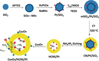
An illustration of the preparation of Co3O4/HCNS/Pt composites. See text for details.
Figure 1 a,b shows the transmission electron microscopy (TEM) of the Pt/SiO2 and mSiO2/Pt/SiO2 templates in dark field. As shown in Figure 1 a, Pt NPs (white dots) with an average size of about 3 nm were uniformly distributed over the SiO2 surface without significant aggregation. The mesoporous silica layer with a thickness of about 40 nm was coated onto the surface of Pt/SiO2 to obtain the monodisperse mSiO2/Pt/SiO2 templates (Figure 1 b). Figure 1 c shows a typical scanning electron microscopy (SEM) image of the HCNS/Pt, displaying a spherical shape with a diameter of around 320 nm, after removing both the dense silica core and the porous silica shell. Observations by TEM shown in Figure 1 d reveal that all Pt NPs of about 3 nm in size were strictly deposited on the inner surface of the HCNS. It is clear that there are no Pt NPs on the shell and outer surface of the HCNS. The mesopore channels in the HCNS/Pt shells can be clearly seen from the TEM image, which agrees well with the N2‐sorption measurements, where a typical IV isotherm featuring with pronounced H‐type hysteresis loop for the HCNS/Pt (Figure S4).15 This porosity is beneficial for enhancing the exchange rate of the solution between the inside and outside of the hollow spheres. It also makes the reaction solution accessible to the active sites where the Pt NPs act as H2 evolution cocatalysts.
Figure 1.
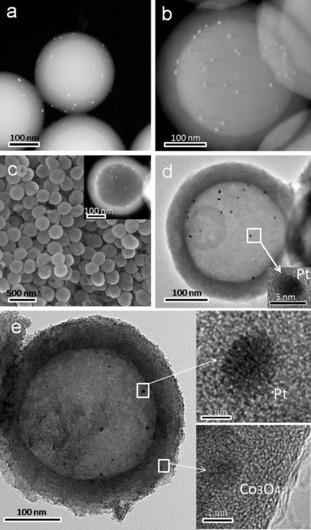
Surface morphology characterization. TEM images of a) Pt/SiO2 and b) mSiO2/Pt/SiO2 templates; c) SEM and d) TEM images of HCNS/Pt samples; e) TEM and HRTEM images of Co3O4/HCNS/Pt samples.
To form the Janus HCNS, Co3O4 NPs were then loaded onto the outer surface of the HCNS/Pt. The low‐magnification TEM image (Figure 1 e) of the Janus Co3O4/HCNS/Pt shows an intact hollow sphere nanostructure with spatially separated cocatalysts, implying the robust stability of the Janus structure. The image clearly shows that Pt NPs of about 3 nm are deposited on the inner shell surface and Co3O4 NPs of approximately 2 nm in diameter are loaded on the outer shell surface of the HCNS. No particulate aggregation of Co3O4 and Pt NPs was observed. The Co3O4 and Pt NPs were also confirmed by high‐resolution TEM images (Figure 1 e insets). These images show that the lattice fringes of approximately 0.243 and 0.223 nm agreed well with the (311) and (111) planes of the Co3O4 and Pt NPs, respectively.16 Additional SEM and TEM images are shown in Figure S1–S3 of the Supporting Information. Figure 2 a exhibits the elemental mapping of the Co3O4/HCNS/Pt, further illustrating the separated dual cocatalysts and the homogeneous distribution of C, N, Pt, and Co in the sphere. Moreover, the construction of the Janus Co3O4/HCNS/Pt is supported by X‐ray diffraction (XRD), Fourier transform infrared (FT‐IR) and X‐ray photoelectron spectroscopy (XPS) analyses (Figure S5–S6). These results also certified that there was no evident structure variation in HCNS after the dual modification.17
Figure 2.
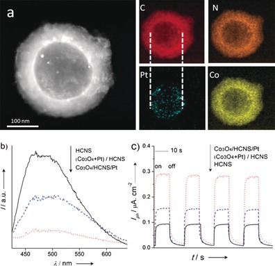
a) elemental mapping of Co3O4/HCNS/Pt samples, b) photoluminescence spectra, and c) the photocurrent generation performance of Co3O4/HCNS/Pt, (Co3O4+Pt)/HCNS and HCNS samples.
UV/Vis spectroscopy was performed to investigate the optical properties of the photocatalyst (Figure S7). The results clearly show that the Co3O4/HCNS/Pt sample had a strong optical absorption from ultraviolet up to 700 nm. These results indicate a fierce interaction between the HCNS and cocatalysts of Co3O4 and Pt NPs.18 The photoluminescence (PL) spectra in Figure 2 b show a strong emission peak, which is assigned to the recombination of the electron‐holes. This recombination process can be suppressed by introducing Co3O4 and Pt NPs that are randomly distributed on the outer surfaces of the HCNS. For the Co3O4/HCNS/Pt sample, the otherwise strong PL is greatly quenched. This should be attributed to the dual cocatalysts that promote the separation and migration of free charge.
The EIS study of the charge transfer rate in the dark reveals the expected semicircular Nyquist plots for the HCNS, Co3O4/HCNS/Pt and (Co3O4+Pt)/HCNS samples. A significantly decreased semidiameter for Co3O4/HCNS/Pt (Figure S8 c) was observed, suggesting the efficient separation of electron‐hole pairs and a rapid interfacial charge transfer occurring on the Co3O4/HCNS/Pt. In Figure 2 c, which shows the transient photocurrent responses, the generation of an enhanced photocurrent for Co3O4/HCNS/Pt, which is nearly two‐times higher than that of the (Co3O4+Pt)/HCNS, is shown, which strongly illustrates that the mobility of the charge carriers is promoted. This result suggests that the improved efficiency of the charge separation and the prolonged lifetime of charge carriers are realized in the Janus HCNS photocatalysts.
The photocatalytic activities of the HCNS photocatalysts with separated and mixed cocatalysts were first evaluated by the half reactions of H2 and O2 evolution. As shown in Figure S9a, the optimum H2 evolution rate (HER) of 96.3 μmol h−1 was achieved for HCNS/1.0 wt % Pt, which is far higher than the initial HCNS (HER is 1.2 μmol h−1). This means that Pt acts as a H2 evolution cocatalyst despite being loaded on the HCNS inner shell, and the solution was able to infiltrate the HCNS shell through the nanopores. Nevertheless, the location of the Pt inside the hollow spheres hinders the mass transfer more or less. There is small activity drop in the H2 evolution rate, compared to the system with 1 wt % Pt on the outer surface (124.2 μmol h−1 vs. 96.3 μmol h−1). After the 3.0 wt % Co3O4 cocatalyst was loaded on the outer surface of the HCNS/Pt, the average HER of the Co3O4/HCNS/Pt sample increased by about 50 %. However, a further increase in the Co3O4 loading amount to 5.0 wt % decreased the H2 evolution rate, as shown in Figure S10. The loading location of the cocatalysts also played a crucial role in the evolution of H2. To further emphasize the necessity of the Janus structure with separated dual cocatalysts for improving the photocatalytic activity, 1.0 wt % Pt and 3.0 wt % Co3O4 were physically mixed and loaded on the outer surface of the HCNS for a photocatalytic test under the same reaction conditions. As expected, there was no significant enhancement in the activity.
The HCNS photocatalysts with spatially separated reduction and oxidation cocatalysts also improved the O2 evolution performance. Figure S9 b clearly shows that merely loading reduction or oxidation cocatalysts or the random distribution of dual cocatalysts on the HCNS leads to relatively low photocatalytic activities. The best O2 evolution rate (OER) of 15.4 μmol h−1 was achieved for the Co3O4/HCNS/Pt photocatalyst. This should be attributed to the separated Co3O4 and Pt cocatalysts, which promote the separation and migration of photogenerated charges during O2 evolution. Moreover, the loading amount of Co3O4 and Pt also played an important role in O2 evolution, as shown in Figure S11.
Not only was there a significant improvement in the photocatalytic activity for the sacrificial evolution of H2 and O2, the HCNS modified with spatially separated cocatalysts can split pure water into H2 and O2 in the absence of sacrificial reagents. As shown in Figure 3 a, the HCNS photocatalyst with the Pt and Co3O4 cocatalysts loaded on the inner and outer surfaces allowed the steady evolution of H2 and O2 in a nearly stoichiometric ratio (H2/O2=2.1). Moreover, the rate of gas evolution increased to about 10 times faster than pure HCNS (0.3 μmol h−1 H2 and 0.1 μmol h−1 O2) and to three‐times faster than that of the random distribution of Pt and Co3O4 on the HCNS outer surface with the same loading amount (Figure 3 b). The origin of the enhanced activity was attributed to the spatially separated reaction sites for the H2 and O2 evolutions. Basically, when the samples were illuminated, the photogenerated holes migrated to the outer surfaces of the oxidation site, where the Co3O4 NPs provide the catalytic active sites for O2 formation. The geometry of the hollow spheres can facilitate the multihole injection and the coupling between the intermediate species to form H2. The photogenerated electrons migrated to the inner surfaces of the reduction site, and water can be efficiently reduced to H2 on the highly dispersed ultrafine Pt NPs. As mentioned above, the Janus HCNS created by the separated dual cocatalysts contributed to the unidirectional migration of the electrons and holes on the Janus surfaces, thereby preventing the reverse reaction of water splitting and decreasing the charge recombination, resulting in the splitting of water into H2 and O2. Note that when applying 200 mg carbon nitride nanosheets modified with Pt and CoOx, the achieved H2 and O2 evolution rate were 12.2 μmol h−1 and 6.3 μmol h−1, while they are 3.1 μmol h−1 (H2) and 1.5 μmol h−1 (O2) for the current system, using 20 mg Janus HCNS.16b Higher activity for photocatalytic overall water splitting was reported for CDocs/g‐C3N4,19 however we also agree with the comments of Ref. 20 that further studies seems to be necessary to confirm the reproducibility of this CDocs/g‐C3N4 work.20
Figure 3.
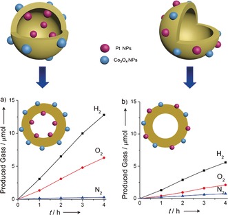
Time courses of photocatalytic evolution of H2 and O2 using a) Co3O4/HCNS/Pt and b) (Co3O4+Pt)/HCNS under UV irradiation (λ>300 nm).
The stability of the Co3O4/HCNS/Pt in this system was evaluated by performing the water splitting reaction for 16 h. After four repeat cycles, there was no noticeable deactivation in the evolution of H2 and O2, as shown in Figure S12. The well‐retained physicochemical properties in both structures and morphologies were further certified by the TEM, XRD, and FTIR analyses of the recycled catalysts (Figure S13, S14). These observations all support the robust nature and high stability of the Co3O4/HCNS/Pt photocatalyst for water splitting.
In conclusion, a polymer photocatalyst modified with two cocatalysts has been established using hollow spheres made of poly‐heptazine building blocks, allowing the interior and exterior surfaces of the shell to be coated separately with Pt and Co3O4 NPs for water splitting. This work demonstrated how nanofabrication technology can promote surface redox reactions by separating incompatible oxidation and reduction sites using a hollow nanostructure with a permeable semiconductor shell. The further optimization of the shell thickness to match the charge diffusion distance is ongoing to maximize the function of the Janus structure, and the application of HCNS could be extended to bioscience. Nevertheless, the hollow nanostructures with Janus surface functionalities that are now being synthesized are beginning to show a faint resemblance to the thylakoid structure, and such structures and functions are always available in case we run out of inspiration. This work should stimulate the study on hollow photosynthetic units for the utilization of solar energy by relevant chemical reactions.
Supporting information
As a service to our authors and readers, this journal provides supporting information supplied by the authors. Such materials are peer reviewed and may be re‐organized for online delivery, but are not copy‐edited or typeset. Technical support issues arising from supporting information (other than missing files) should be addressed to the authors.
Supplementary
Acknowledgements
This work was financially supported by the National Basic Research Program of China (2013CB632405) and the National Natural Science Foundation of China (21425309).
D. Zheng, X.-N. Cao, X. Wang, Angew. Chem. Int. Ed. 2016, 55, 11512.
Contributor Information
Dandan Zheng, http://wanglab.fzu.edu.cn.
Prof. Xinchen Wang, Email: xcwang@fzu.edu.cn
References
- 1. Maeda K., Teramura K., Lu D., Takata T., Saito N., Inoue Y., Domen K., Nature 2006, 440, 295. [DOI] [PubMed] [Google Scholar]
- 2. Yang H., Sun C., Qiao S., Zou J., Liu G., Smith S., Cheng H., Lu G., Nature 2008, 453, 638–641. [DOI] [PubMed] [Google Scholar]
- 3.
- 3a. Esper B., Badura A., Rögner M., Trends Plant Sci. 2006, 11, 543–549; [DOI] [PubMed] [Google Scholar]
- 3b. Blankenship R., Plant Physiol. 2010, 154, 434–438. [DOI] [PMC free article] [PubMed] [Google Scholar]
- 4.
- 4a. Ferreira K., Iverson T., Maghlaoui K., Barber J., Iwata S., Science 2004, 303, 1831–1838; [DOI] [PubMed] [Google Scholar]
- 4b. Umena Y., Kawakami K., Shen J., Kamiya N., Nature 2011, 473, 55–60. [DOI] [PubMed] [Google Scholar]
- 5.
- 5a. Gregory S., Tessa R., Elizabeth L., Ahn T., Mancal T., Cheng Y., Blankenship R., Fleming G., Nature 2007, 446, 782–786. [DOI] [PubMed] [Google Scholar]
- 6. Maeda K., Xiong A., Yoshinaga T., Ikeda T., Sakamoto N., Hisatomi T., Takashima M., Lu D., Kanehara M., Setoyama T., Teranishi T., Domen K., Angew. Chem. Int. Ed. 2010, 49, 4096–4099; [DOI] [PubMed] [Google Scholar]; Angew. Chem. 2010, 122, 4190–4193. [Google Scholar]
- 7.
- 7a. Wang D., Hisatomi T., Takata T., Pan C., Katayama M., Kubota J., Domen K., Angew. Chem. Int. Ed. 2013, 52, 11252–11256; [DOI] [PubMed] [Google Scholar]; Angew. Chem. 2013, 125, 11462–11466; [Google Scholar]
- 7b. Zhang Q., Lima D., Lee I., Zaera F., Chi M., Yin Y., Angew. Chem. Int. Ed. 2011, 50, 7088–7092; [DOI] [PubMed] [Google Scholar]; Angew. Chem. 2011, 123, 7226–7230. [Google Scholar]
- 8.
- 8a. Shen L., Yu L., Yu X., Zhang X., Lou X., Angew. Chem. Int. Ed. 2015, 54, 1868–1872; [DOI] [PubMed] [Google Scholar]; Angew. Chem. 2015, 127, 1888–1892; [Google Scholar]
- 8b. Liang J., Yu X., Zhou H., Wu H., Ding S., Lou X., Angew. Chem. Int. Ed. 2014, 53, 12803–12807; [DOI] [PubMed] [Google Scholar]; Angew. Chem. 2014, 126, 13017–13021. [Google Scholar]
- 9.
- 9a. Liu B., Liu L., Lang X., Wang H., Lou X., Aydil E., Energy Environ. Sci. 2014, 7, 2592–2597; [Google Scholar]
- 9b. Li A., Wang T., Chang X., Cai W., Zhang P., Zhang J., Gong J., Chem. Sci. 2016, 7, 890–895. [DOI] [PMC free article] [PubMed] [Google Scholar]
- 10. Yang C., Ma B., Zhang L., Lin S., Ghasimi S., Landfester K., Zhang K., Wang X., Angew. Chem. Int. Ed. 2016, 55, 9202–9206; [DOI] [PubMed] [Google Scholar]; Angew. Chem. 2016, 128, 9348–9352. [Google Scholar]
- 11. Xu X., Asher S., J. Am. Chem. Soc. 2004, 126, 7940–7945. [DOI] [PubMed] [Google Scholar]
- 12.
- 12a. Sun J., Zhang J., Zhang M., Antonietti M., Fu X., Wang X., Nat. Commun. 2012, 3, 1139–1145; [Google Scholar]
- 12b. Wang X., Maeda K., Thomas A., Takanabe K., Xin G., Carlsson J., Domen K., Antonietti M., Nat. Mater. 2009, 8, 76–80; [DOI] [PubMed] [Google Scholar]
- 12c. Zheng Y., Lin L., Wang B., Wang X., Angew. Chem. Int. Ed. 2015, 54, 12868–12884; [DOI] [PubMed] [Google Scholar]; Angew. Chem. 2015, 127, 13060–13077; [Google Scholar]
- 12d. Kuriki R., Matsunaga H., Nakashima T., Wada K., Yamakata A., Ishitani O., Maeda K., J. Am. Chem. Soc. 2016, 138, 5159–5170; [DOI] [PubMed] [Google Scholar]
- 12e. Kuriki R., Sekizawa K., Ishitani O., Maeda K., Angew. Chem. Int. Ed. 2015, 54, 2406–2409; [DOI] [PubMed] [Google Scholar]; Angew. Chem. 2015, 127, 2436–2439; [Google Scholar]
- 12f. Maeda K., Sekizawa K., Ishitani O., Chem. Commun. 2013, 49, 10127–10129; [DOI] [PubMed] [Google Scholar]
- 12g. Wang S., Wang X., Angew. Chem. Int. Ed. 2016, 55, 2308–2320; [DOI] [PubMed] [Google Scholar]; Angew. Chem. 2016, 128, 2352–2364. [Google Scholar]
- 13.
- 13a. Zhang J., Zhang M., Yang C., Wang X., Adv. Mater. 2014, 26, 4121–4126; [DOI] [PubMed] [Google Scholar]
- 13b. Zheng D., Pang C., Wang X., Chem. Commun. 2015, 51, 17467–17470. [DOI] [PubMed] [Google Scholar]
- 14. Stöber W., Fink A., J. Colloid Interface Sci. 1968, 26, 62–69. [Google Scholar]
- 15. Jun Y., Park J., Lee S., Thomas A., Hong W., Stucky G., Angew. Chem. Int. Ed. 2013, 52, 11083–11087; [DOI] [PubMed] [Google Scholar]; Angew. Chem. 2013, 125, 11289–11293. [Google Scholar]
- 16.
- 16a. Zhang J., Grzelczak M., Hou Y., Maeda K., Domen K., Fu X., Antonietti M., Wang X., Chem. Sci. 2012, 3, 443–446; [Google Scholar]
- 16b. Zhang G., Lan Z., Lin L., Lin S., Wang X., Chem. Sci. 2016, 7, 3062–3066. [DOI] [PMC free article] [PubMed] [Google Scholar]
- 17. Zheng Y., Jiao Y., Zhu Y., Li L., Han Y., Chen Y., Du A., Jaroniec M., Qiao S., Nat. Commun. 2014, 5, 3783–3791. [DOI] [PubMed] [Google Scholar]
- 18.
- 18a. Zheng D., Pang C., Liu Y., Wang X., Chem. Commun. 2015, 51, 9706–9709; [DOI] [PubMed] [Google Scholar]
- 18b. Martin D., Qiu K., Shevlin S., Handoko A., Chen X., Guo Z., Tang J., Angew. Chem. Int. Ed. 2014, 53, 9240–9245; [DOI] [PMC free article] [PubMed] [Google Scholar]; Angew. Chem. 2014, 126, 9394–9399. [Google Scholar]
- 19. Liu J., Liu Y., Liu N., Han Y., Zhang X., Huang H., Lifshitz Y., Lee S., Zhong J., Kang Z., Science 2015, 347, 970–974. [DOI] [PubMed] [Google Scholar]
- 20.
- 20a. Wang Q., Hisatomi T., Jia Q., Tokudome H., Zhong M., Wang C., Pan Z., Takata T., Nakabayashi M., Shibata N., Li Y., Sharp I., Kudo A., Yamada T., Domen K., Nat. Mater. 2016, 15, 611–615; [DOI] [PubMed] [Google Scholar]
- 20b. Ong W., Tan L., Ng Y., Yong S., Chai S., Chem. Rev. 2016, 116, 7159–7329. [DOI] [PubMed] [Google Scholar]
Associated Data
This section collects any data citations, data availability statements, or supplementary materials included in this article.
Supplementary Materials
As a service to our authors and readers, this journal provides supporting information supplied by the authors. Such materials are peer reviewed and may be re‐organized for online delivery, but are not copy‐edited or typeset. Technical support issues arising from supporting information (other than missing files) should be addressed to the authors.
Supplementary