Abstract
Shape‐dependent catalysis and sensing behaviours are primarily focused on nanocrystals enclosed by low‐index facets, especially the three basic facets ({100}, {111}, and {110}). Several novel strategies have recently exploded by tailoring the original nanocrystals to greatly improve the catalysis and sensing performances. In this Review, we firstly introduce the synthesis of a variety of Cu2O nanocrystals, including the three basic Cu2O nanocrystals (cubes, octahedra and rhombic dodecahedra, enclosed by the {100}, {111}, and {110} facets, respectively), and Cu2O nanocrystals enclosed by high‐index planes. We then discuss in detail the three main facet‐controlled synthetic strategies (deposition, etching and templating) to fabricate Cu2O‐based nanocrystals with heterogeneous, etched, or hollow structures, including a number of important concepts involved in those facet‐controlled routes, such as the selective adsorption of capping agents for protecting special facets, and the impacts of surface energy and active sites on reaction activity trends. Finally, we highlight the facet‐dependent properties of the Cu2O and Cu2O‐based nanocrystals for applications in photocatalysis, gas catalysis, organocatalysis and sensing, as well as the relationship between their structures and properties. We also summarize and comment upon future facet‐related directions.
Keywords: catalysis, Cu2O, facet‐controlled, nanocrystals, sensing
1. Introduction
In addition to the shapes of nanocrystals (NCs), their surface conditions (surface energies and electronic structures) also determine their physical and chemical properties.1 Facets with distinctive crystallographic feature possess different atomic terminated characters, which have shown big differences in catalysis and sensing.2, 3, 4, 5, 6, 7, 8, 9 Over the past decades, the understanding, design, and optimization of metal oxide NCs enclosed by well‐defined facets has been widely explored.7, 10, 11, 12, 13, 14, 15, 16 It is noteworthy that, although high‐index facets that have high‐density atomic edges with corners and plentiful unsaturated active sites are promising for catalysis and sensing applications, those facets are often unstable, and hardly obtained by traditional chemical methods.17, 18, 19, 20, 21, 22, 23 Thus, the shape‐dependent catalysis and sensing behaviours is primarily focused on NCs enclosed by low‐index facets, especially the three basic facets (i. e., the {100}, {111}, and {110} facets).6, 7, 8, 9, 12, 13, 14, 16, 24, 25, 26, 27, 28, 29, 30, 31, 32, 33, 34 For instance, by employing hydrofluoric acid as a capping agent (CA), H. G. Yang et al.34 were the first to obtain uniform anatase TiO2 single crystals with a high percentage (47%) of highly reactive {001} facets, which possessed promising applications in sensors, solar cells and photocatalysis. Besides the various routes for the synthesis of NCs, several novel strategies have recently exploded by carving, modifying, or transforming the original NCs that greatly improve the catalysis and sensing performances.6, 27, 30, 33, 35, 36, 37, 38, 39, 40, 41, 42, 43, 44, 45, 46, 47, 48, 49, 50, 51, 52 For example, X. Chen et al.51 disordered the surface layers of nanophase TiO2 by hydrogenation. The disorder‐engineering substantially improved the solar photocatalytic performances of TiO2. R. Long et al.30 fabricated a metal–semiconductor hybrid structure in which Pd nanocubes exposed with {100} facets were deposited on TiO2 supports. By changing the light intensity irradiated on Pd–TiO2 heterogeneous structures, the charge condition of the Pd surface could be rationally modulated, and thus the function of Pd nanocubes in organic oxidation reactions and O2 activation could be tailored. Our group35 synthesized Ni–Co amorphous double hydroxides nanocages with tunable Ni/Co molar ratio by using Cu2O octahedra as templates. The obtained amorphous NiCo2.7(OH)x nanocages displayed outstanding applications in electrochemical water oxidation.
In this context, the inexpensive, non‐toxic and abundantly available Cu2O nanomaterials, with unique optical and electrical properties,4, 9, 10, 53, 54, 55, 56, 57, 58 have recently aroused general attention, due to their outstanding morphology‐dependent applications in catalysis (gas oxidation,2, 3, 17, 59, 60, 61 CO2 reduction,62, 63, 64, 65 organocatalysis,14, 24, 32, 40, 50, 66 electrocatalysis,28, 67, 68 and photocatalysis36, 44, 69, 70, 71, 72, 73, 74, 75, 76, 77, 78, sensing (gas sensors,8, 79, 80, 81, 82, 83 ion detection,29 and surface‐enhanced Raman scattering (SERS)84, 85, 86, 87, 88, 89, as adsorbents,7, 90 biotoxicity,26, 91, 92 as chemical templates35, 38, 45, 47, 48, 49, 52, 93, 94, 95, 96 and energy‐related processes (water splitting,97, 98, 99, 100 solar energy conversion101, 102 and lithium‐ion batteries25, 103. Compared to Cu2O nanowires72, 81, 104, 105, 106 or nanorods,83, 107 nanospheres,53, 64, 76, 82, 84, 87, 90, 108, 109 hollow structures,42, 57, 67, 73, 79, 94, 95, 101, 110, 111, 112, 113, 114 self‐assembled superstructures,8, 115, 116 and Cu2O polyhedra enclosed by high‐index planes,17, 117, 118, 119, 120, 121, 122 the preparation of Cu2O polyhedra enclosed by low‐index planes2, 3, 7, 8, 9, 14, 25, 26, 29, 32, 55, 57, 66, 68, 75, 91, 92, 123, 124, 125, 126, 127, 128, 129 is simple and large‐scale. Even more importantly, several novel facet‐controlled routes, including carving,42, 44, 110, 130, 131, 132 modifying36, 40, 50, 70, 73, 133 and converting,35, 38, 45, 47, 48, 49, 52, 60, 93, 134 have been recently carried out on the basis of the well‐defined facets of Cu2O NCs, especially in cubic, octahedral, and rhombic dodecahedral crystals (the three basic Cu2O crystals, enclosed by the {100}, {111}, and {110} low‐index facets, denoted as c‐Cu2O, o‐Cu2O and d‐Cu2O, respectively), to tailor their facet‐dependent properties. It is noteworthy that although smaller NCs possess higher activities in catalysis and sensing than larger NCs, the reported activity of of smaller Cu2O NCs8, 32, 68 remain ≈1 order of magnitude lower than those of larger Cu2O NCs; thus, larger Cu2O NCs are often used as precursors for further carving, modifying and transforming.
In this review, we comprehensively summarized the recent progresses in facet‐controlled synthetic strategies for the preparation of Cu2O‐based NCs as well as tailoring their facet‐dependent properties of catalysis and sensing. We begin with a brief discussion of solution phase synthetic strategy of the three basic Cu2O NCs (c‐Cu2O, o‐Cu2O and d‐Cu2O) and Cu2O NCs enclosed by high‐index planes, as well as the key role of CA for controlling their crystallographic facets. We then introduce in detail the three main facet‐controlled synthetic strategies (deposition, etching and template) on the Cu2O NCs to fabricate Cu2O‐based NCs with heterogeneous, etched, or hollow structures, and discuss in detail a number of important concepts involved in those facet‐controlled routes, including the selective adsorption of CA for protecting special facets, and the impacts of surface energy and active sites on reaction activity trends. Finally, we summarize the exciting facet‐dependent properties of Cu2O and Cu2O‐based NCs for applications of photocatalysis, gas catalysis, organocatalysis and sensing, as well as the relationship between their structures and properties. We expect that this review will inspire facet‐controlled methodologies, and more examples of these facet‐dependent properties should be continuously explored, endowing nanomaterials with excellent properties for numerous applications.
2. Basic Growth Strategies for Cu2O Polyhedra
Cu2O crystallizes in a cubic structure. A tetrahedron of Cu atoms encircle every O atom, and every Cu atom possesses two neighboring O atoms as illustrated in the model of unit cell123 (Figure 1 a). For the {100}, {111} and {110} facets, the three low‐index facets of Cu2O crystals, it is well established that the surface energy is closely related to the density of under‐coordinated Cu atoms.75 The atomic arrangements along three low‐index facets of Cu2O are illustrated in Figure 1b– 1d. Only O atoms are terminated in the {100} facet, leading to electric neutrality (Figure 1b).44 By contrast, Cu atoms at the {111} facet are coordinated unsaturated. Each two Cu atoms have a dangling bond perpendicular to the {111} facet illustrated by the pink circles in Figure 1c, which make them positively charged.7 Similarly, the {110} facet has the same terminated Cu atoms with dangling Cu atoms (illustrated by the pink circles in Figure 1d), while the number of dangling Cu atoms on {110} plane per unit surface area is approximately 1.5 times higher than that on {111} plane.75 Thus, the {110} facet should be more positively charged than the {111} facet, and the surface energies of Cu2O are in the following order: γ {100} < γ {111} < γ {110}.
Figure 1.
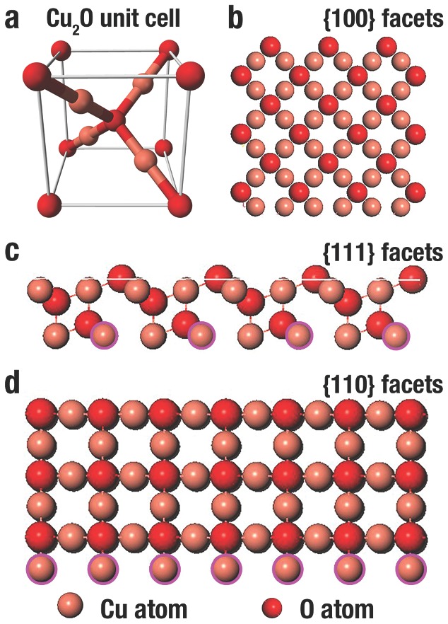
Illustration of the a) unit cell of cuprite Cu2O, and b–d) the crystal structure of Cu2O {100}, {111} and {110} facet, respectively. The light pink spheres are Cu atoms and the red spheres are O atoms. The dangling Cu atoms are marked by dark pink circles.
However, the conditions of high‐index facets of Cu2O NCs are distinctly different. For example, the {311}, {522} and {211} facets can be displayed by a terrace × step as 2 {100} × {111}, 3 {100} × 2 {111}, and {100} × {111}, respectively. That is, they possess two {100} terraces and one {111} step, three {100} terraces and two {111} steps, and one {100} terrace and one {111} step, respectively (Figure 2 ).135 Therefore, compared to low index {100} and {111} facets, the numerous kinks and steps endow those high‐index facets with higher surface energies.
Figure 2.
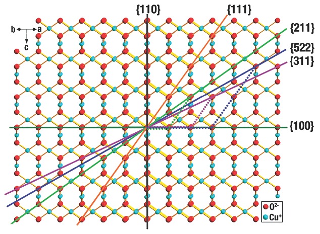
Illustration of the crystal structure of Cu2O viewed from the direction parallel to the {110} facets. Reproduced with permission.135 Copyright 2012, Royal Society of Chemistry.
Cu2O crystals with clean facets were primarily synthesized through solution phase synthesis (hydrothermal and solvothermal process),4, 7, 8, 17, 44, 75, 101, 107, 122, 124 because that route could delicately tailor the exposed facets of crystals, through controlling the nucleation and growth behaviours (especially growth rates in different directions) of crystals.136, 137 The Wulff construction determines the equilibrium or natural morphologies of crystals, because minimizing the total surface energies mainly lead the shape evolution of crystal.123 Based on the Gibbs–Wulff's theorem, the facets with higher surface energies always grow rapidly and finally decrease or vanish from the ultimate morphologies, while the crystal facets with lower surface energies grow slowly and are preserved in the final structure.5 However, selective surface stabilization of appropriate organic or inorganic additives (molecules or ions) as CA can effectively decrease the surface energies and retard the crystal growth along their normal orientations (Figure 3 ).5, 7 CAs tend to selectively adsorb on the surface with higher surface energy, which consequently lead to delicately tuning of the percentages of different facets of crystals.7, 138
Figure 3.
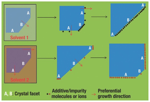
Illustration of facet‐control of crystal facets by solvent and additive/impurity molecules or ions. Reproduced with permission.5 Copyright 2011, Royal Society of Chemistry.
To date, CAs have played an important role on shape‐controlled synthesis of NCs,137, 138, 139, 140, 141, 142 and there are many successful examples in preparing Cu2O NCs.7, 8, 75, 107, 122, 125, 143 We will introduce some classic synthetic routes of Cu2O NCs enclosed by low‐index facets. For instance, by using the preferential adsorption of polyvinylpyrrolidone (PVP) on the {111} facets, our group7 successfully achieved the systematic morphology evolution from c‐Cu2O to o‐Cu2O (Figure 4 a), which was in accordance with the identical evolution in shapes of cubic‐structured crystal depending on the ratio R (the growth rate ratio of <100> to <111>).144 The negatively charged O atoms of “—C = O” in PVP (Figure 4b) would strongly interact with the positively charged dangling Cu atoms on {111} facet to stabilize the crystal surfaces. The ratio of the surface area of {111} to {100} could be controlled by increasing the concentration of PVP (Figure 4c). It is worth noting that {110} facets could not be obtained by only using PVP as CA. The reason is that the relatively strong adsorption of PVP is not enough to reduce the growth rate of {110} facets. Interestingly, L. Gao et al.125 reported that, by employing oleic acid with stronger adsorption ability as the CA, rhombic dodecahedron Cu2O NCs totally enclosed by {110} facets could be obtained. With the increasing concentrations of oleic acid, the morphologies of Cu2O crystals were evolved from c‐Cu2O, o‐Cu2O, {110} truncated o‐Cu2O, to d‐Cu2O. During this process, oleic acid firstly adsorbed on the {111} facets to form o‐Cu2O; with continuous increasing of the concentration of oleic acid, the oleic acid began to adsorb on the {110} crystal planes. The area of the {110} surface was ever increasing, while the {111} surfaces gradually disappeared. Finally, d‐Cu2O enclosed by {110} facets were synthesized. By using sodium dodecyl sulfate (SDS) as CA, M. H. Huang et al.75 synthesized a succession of Cu2O NCs with morphology evolution from c‐Cu2O to d‐Cu2O (Figure 5 ). The adding NH2OH·HCl played a dual role in reducing Cu(OH)2 to Cu2O and controlling the pH. By increasing the amount of NH2OH·HCl, the gradually decreased solution pH that caused by the HCl released from NH2OH·HCl would retard the formation rate of Cu2O. The rate for growing c‐Cu2O was within 1 min, but that for d‐Cu2O was decreased to 60 min.
Figure 4.
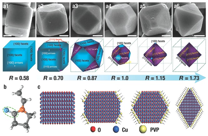
a) SEM of the Cu2O polyhedral NCs depending of the ratio R (the ratio of the growth rate along <100> to that of <111>), and the corresponding 3D structures. Scale bar = 300 nm. b) The molecular formula of PVP. c) PVP adsorption during the growth process of Cu2O NCs. Reproduced with permission.7 Copyright 2009, Royal Society of Chemistry.
Figure 5.
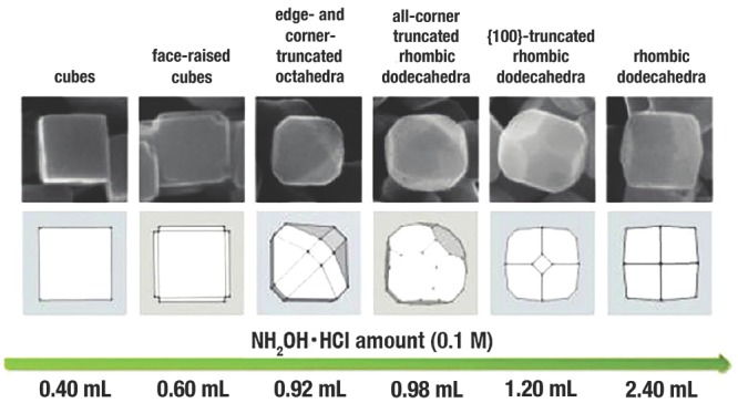
SEM images and the corresponding geometry models with shape evolution from c‐Cu2O to d‐Cu2O. Reproduced with permission.75 Copyright 2012, American Chemical Society.
This suggested that a slower growth rate contributed to the generation of d‐Cu2O. Furthermore, a slower growth rate, namely a kinetic‐controlled process is essential for obtaining high‐index facets. C. Wang et al.17 reported 50‐facet Cu2O polyhedral microcrystals partially enclosed by {311} high‐index facets. A low concentration of copper salts as well as a weak reducing agent contributed to the kinetic‐controlled process, and the decreased viscosities caused by the extra ethanol may improve the diffusions of the reactants. Those above factors finally contributed to the generation of the novel configurations. So far, another shape of 50‐facet Cu2O architectures with {311}, {522}, {211} facets,135 50‐facet and 74‐facet Cu2O polyhedra with {211}, {522} and {744} facets117 and 30‐facet Cu2O polyhedra with {332} facets121 could also be obtained through different kinetic‐controlled process by changing the concentration of reactants.
To sum up, by using CA or kinetic‐controlled process, Cu2O polyhedra with smooth surfaces could be easily obtained, which lays a solid foundation for further tailoring and investigation of the facet‐dependent performance.
3. Facet‐Controlled Deposition
Recently, numerous studies are focused on the formation of heterogeneous structures by rational growing supported substances (typically noble metal nanoparticles) on the support (typically metal oxides), since metal oxides can not only serve as a support for a better dispersibility of disperse metal nanoparticles (NPs), but also enhance the catalytic abilities by interacting with the metal NPs.6, 27, 30, 33, 36, 40, 50, 61, 145, 146, 147 Despite many successful examples on the synthesis of heterogeneous structures, it is noteworthy that the spatially controllable deposition of noble metal NPs on metal oxide support is a significant topic. For example, R. G. Li et al.27 demonstrated that for the monoclinic BiVO4 enclosed by {110} and {010} facets, photogenerated holes and electrons were transferred to the {110} and {010} surfaces for oxidation and reduction reactions respectively, due to the different energy levels of the two facets. When MnOx (oxidation co‐catalyst) and Pt (reduction co‐catalyst) were preferentially deposited by light‐induced deposition onto the {110} and {010} facets of BiVO4, the performances of photocatalytic water splitting were significantly improved. They further optimized the experiments to design two highly efficient photocatalyst systems (M/MnOx/BiVO4 and M/Co3O4/BiVO4, where M stands for noble metals).6 Besides the intrinsic nature of separation of charge between the two facets, the synergetic effect of those catalysts also played a significant role in enhancing photocatalytic performances. So far, lots of Cu2O‐based heterogeneous structures have been reported,33, 36, 40, 50, 61, 70, 76, 77, 78, 89, 108, 148 and the synthetic routes mainly focused on light‐induced deposition33, 70 or galvanic deposition.28, 36, 40, 50, 76, 89, 148 In this section, we plan to discuss the site‐selective deposition of noble NPs on the preferential faces, edges, or corners of Cu2O crystals.
K. S. Choi et al.126 synthesized o‐Cu2O by employing the preferential adsorption of SDS on {111} facets (Figure 6 a, left). They then demonstrated that the selective adsorption of SDS could be used for preferentially blocking the nucleation of Au NPs on these planes (Figure 6a, right).133 In the presence of SDS, Au NPs only electrodeposited on the {100} facets of truncated octahedral Cu2O; however, Au NPs would form on both {100} and {111} facets in the absence of SDS.
Figure 6.
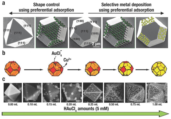
a) Using selective adsorption of SDS for controlling morphology (left) and for Au preferential deposition (right). Reproduced with permission.133 Copyright 2009, American Chemical Society. b) Selective growth of Au NPs on {111} facets of Cu2O microcrystals. Reproduced with permission.28 Copyright 2011, American Chemical Society. c) Illustration of the shape evolution of the preferential growth of Au NPs on o‐Cu2O. Reproduced with permission.148 Copyright 2013, Royal Society of Chemistry.
By contrast, galvanic or light‐induced process can control the site‐selective deposition in the absence of CAs. X. W. Liu28 reported that during the in situ reduction of AuCl4 − precursors, a galvanic process occurred that Au NPs selectively grew on {111} facets of Cu2O truncated octahedra and cubooctahedra (Figure 6b), which can be formulated as shown in Eq. (1):
| (1) |
The galvanic deposition selectively occured on the {111} facet of Cu2O since that metallic component prefers to nucleate on highly active surface sites or defects with a large curvature, in which the {111} facet is more active than {100} facet due to the higher surface energy. By changing the concentration of the AuCl4 − precursor, the density and size of Au NPs can also be controlled. Unlike galvanic deposition, light‐induced deposition can lead to a distinct selectivity. After light illumination, the photogenerated electrons preferred to transfer from bulk to {100} surface of c‐Cu2O, which was contributed to reduce metal ions to pure metal. In contrast, the photoexcited holes mostly accumulated on the {111} facet that inhibited the reduction of metal ions.33
Edges and corners with a large curvature also play a key role in selective growth. M. L. Du et al.148 reported a sequential growth process of Au NPs on o‐Cu2O. With the increasing concentration of AuCl4 − ions, Au NPs were sequentially deposited on the corners, edges and facets of o‐Cu2O (Figure 6c). The surface energy distribution follows the order of corners > crystal edges > {111} facets, and results in selective growth and evolution of the heterogeneous structures.
4. Facet‐Controlled Etching
Recently, much effort is dedicated to a so‐called “top‐down” engineering approach that delicately modifies crystals to create more highly active sites by etching and crystal cut, for the purpose of improvement the physical and functional properties of crystals.43, 46, 51, 68, 149, 150, 151, 152, 153, 154 (In this section, the “top‐down” means crystal carving without phase transformation; while the “top‐down” in the next section refers to total phase transformation from Cu2O to various hollow structures.) To date, various metal or alloys (Ag,151 Rh,152 Pd,153 Pd‐Pt,139 Pt,155 and PtxNiy 150 etc.) and metal oxide (Cu2O,42, 44, 60, 66, 85, 110, 113, 130, 132 TiO2,13, 51 Fe2O3,46 and ZnO154 etc.) NCs with sophisticated structures have been fabricated through a chemical “top‐down” route. The first step is partial dissolution of the mother‐crystal, namely via a surface etching process, in which the etching agent (ions or molecules) chelates to exposed facets by cations, and then leads the chelated surfaces to dissolve.5 A subsequent step of surface recrystallization on the residual surfaces of mother‐particles may occur, which make the mother‐particles roughen or convert to more stable facets.5 In other words, if the surface recrystallization process does not happen, the continuous surface etching process would contribute to the transformation from the mother‐crystal particles to hollow42, 88, 110, 113, 114, 150 or branch41, 151, 152, 155 structures.
In the absence of CAs, when many kinds of facets are exposed on the surface of a precursor, the etching will proceed with facet selectivity beginning with the facet(s) with the highest active sites. Although Ag2O has an identical cuprite crystal structure, the order of facet stability for Ag2O to chemical etching by NH3 and NaOH is {111} > {110} > {100}.31 The drastically different facet stability is caused by the pH of the reaction system. The {111} and {100} facet of Ag2O are terminated with Ag atoms and O atoms, respectively; while the {110} facet consists of rows of surface O and Ag atoms. Under alkaline condition, OH− ions would strongly interact with Ag atoms on {111} facets and protect them from etching by NH3, while a protecting ionic layer does not exist for the {100} facets, leading to their dissolution by NH3. However, in an acidic environment, the {110} and {111} facets of Ag2O with high surface energy are unstable, and those facets would transform into {100} facets with low surface energy.
An appropriate CA (ions or molecules) could selectively adsorb on special facets to avoid dissolution. Thus, the existing CA is a critical factor when inferring the reacted facet in the initiation of an etching process. For example, using phosphate ions as CA selectively protected the {110} facet of Fe2O3 NCs; the etching by oxalic acid preferentially occurred along the [001] direction. Hence, the Fe2O3 NCs with minor {001} and major {110} facets would transform into Fe2O3 discs with minor {110} and major {001} facets.46 We intend to conclude the face‐dependent etching on Cu2O NCs, and study the formation mechanisms, including preferentialadsorption, etching, and others.
CA adsorption is conducive to the selective etching on different positions of Cu2O NCs. M. H. Huang et al.114 obtained Cu2O nanocages and nanoframes with empty {100} or {110} facets from Cu2O truncated rhombic dodecahedra. Because SDS selectively adsorbed and protected the {110} facets, the etching process occurred prior to the {100} facets. Thus, truncated rhombic dodecahedral Cu2O nanoframes consisting of empty {100} facets and {110} skeleton facets (type‐I nanoframe) were formed first (Figure 7 a). Then, {100} facets were filled during the further reaction, generating nanocages. By adding ethanol and subsequent sonication of the reaction system, the adsorbed SDS on {110} facets of the nanocages was detached which conduced preferential etching of the {110} facets via HCl, leading to the generation of elliptical pores on {110} facets (type‐II nanoframes in Figure 7a).
Figure 7.
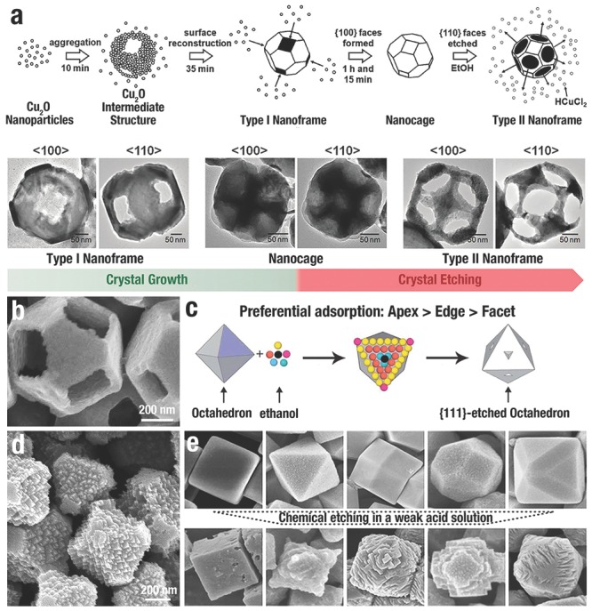
a) Growth schematic and SEM images of Cu2O with empty {100} facets (type I nanoframes), {110} facets (type II nanoframes) and nanocages. Reproduced with permission.114 Copyright 2008, American Chemical Society. b) High‐magnification SEM image of a Cu2O nanoframe with empty {100} faces. Reproduced with permission.42 c) The preferential adsorption between ethanol molecules and o‐Cu2O crystals: apexes (pink) > edges (yellow) > facets (orange/pea green/black)”. Reproduced with permission.130 Copyright 2011, Royal Society of Chemistry. d) SEM images of Cu2O jagged polyhedrons. Reproduced with permission.44 e) The morphological evolution of uniform Cu2O NCs in a weak acetic acid solution. Reproduced with permission.132 Copyright 2011, American Chemical Society.
In order to obtain more delicate structures, a “pre‐synthesis strategy” has been widely used to carve NCs involving a two‐stage route where NCs acted as precursors for subsequent etching.41, 42, 46, 150, 151 H. B. Yang et al.42 reported other Cu2O nanocages and nanoframes with empty {100} facets from truncated octahedral Cu2O precursors (Figure 7b). The capping PVP preferentially adsorbed onto the {111} facets of the Cu2O polyhedra and “freezes” the {111} planes; thus, the subsequent oxidative etching selectively occurred on the {100} facets. Similarly, S. D. Sun et al.130 reported the branching growth of Cu2O NCs via selective oxidative etching with ethanol solution (Figure 7c). As for o‐Cu2O, the adsorption energies (E) are in the following order: E apex > E edge > E facet, according to the different numbers of coordinated O atoms. Hence, the relative order of ethanol molecules adsorbed on o‐Cu2O should be facet < edge < apex. Therefore, the selective oxidative etching was reversed to the order of adsorption, from the centre of {111} facets, edges, to apexes.
Without CAs, the {111} or {110} facets with higher surface energy are etched prior to the {100} facet. Q. Hua et al.131 reported the facet‐dependent oxidative dissolution of c‐Cu2O, o‐Cu2O and d‐Cu2O NCs in NH3 solution. The relative stability of different Cu2O crystal facets in NH3 solution in the sequence of {110} < {111} < {100} that were reversed to the order of the surfaces energies. When changing to a weak acid solution132 instead of the aqueous ammonia, the stability of Cu2O facets also followed the order of {100} > {111} > {110}, which determined the extent of oxidative dissolution. Stable {100} facets were preserved, but unstable {110} and {111} facets were etched with newly formed {100} facets (Figure 7e). Using truncated octahedron Cu2O NCs exposed with {100} and {111} facets as precursors, our group44 created Cu2O jagged polyhedra totally enclosed by {100} facets, with numerous {111} corners and {110} edges (Figure 7d). Due to the Cu dangling bonds, O2 molecules strongly interacted with the {111} facet, making those facets easily dissolute. The selective oxidative etching only occurred on the {111} facets. New {100} facets emerged from the {111} facets by etching, while the original {100} facets remained unchanged.
5. Sacrificial Templates
Due to the large surface area, low density, good surface permeability, and high loading capacity, the shape‐controllable synthesis of hollow/cage‐like nanostructures, even with non‐spherical shapes and regular interiors, has received extensive attention in recent years because of their widespread applications.38, 47, 156 A template‐assisted synthetic strategy is straightforward for the preparation of nanocages and the possible creation of nonspherical nanostructures.47, 49, 157 The following steps occur during the template synthesis of cage‐like/hollow nanostructures: i) synthesizing template, ii) using template to create target structure, iii) removing template (if necessary).157 Recently, one “top‐down” synthetic route has been extensively studied by using the low‐cost and highly chemically reactive Cu2O NCs (cubes, octahedra, and other highly symmetrical structures) as the sacrificial template, to create various hollow, non‐spherical nanostructures, including hollow metal oxides,35, 38, 45, 47, 48, 49, 52 hollow copper sulfide (CuxSy),93, 158, 159, 160, 161, 162 and hollow metals or alloys.134, 163, 164, 165 In this section, we summarize the recent progress in Cu2O sacrificial templates, and discuss the three major routes as shown in Figure 8 (galvanic replacement, the Kirkendall effect, and coordinating etching).
Figure 8.
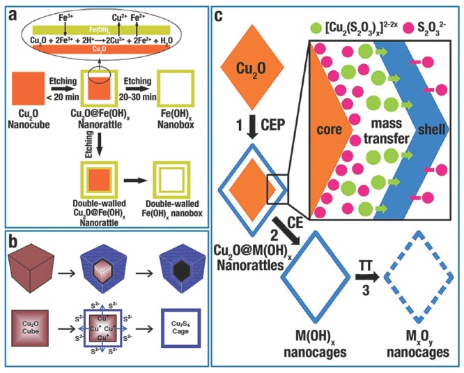
Growth schematic of a) single‐walled or double‐walled Fe(OH)x by galvanic replacement. Reproduced with permission.49 Copyright 2010, American Chemical Society. b) Cu7S4 hollow nanocubic structure by Kirkendall effect. Reproduced with permission.158 Copyright 2014, Royal Society of Chemistry. c) M(OH)x (M = Mn, Fe, Co, Ni, and Zn) nanocages by coordinating etching of Cu2O NCs, and the production of MxOy by thermal treating of relevant M(OH)x. Abbreviations: CEP, coordinating etching and precipitating; CE, coordinating etching; TT, thermal treatment. Reproduced with permission.47 Copyright 2013, American Chemical Society.
5.1. Galvanic Replacement
Galvanic replacement is an electro‐chemical process, in which the sacrificial template is oxidized and dissolved in the solution; meanwhile another metal ion with a higher reduction potential would be reduced and deposited on the surface of the template, and finally inherits the original structure.39 For example, due to the lower standard reduction potential of Cu2+/Cu2O (0.203 V vs standard hydrogen electrode (SHE)) than that of the Fe3+/Fe2+ pair (0.77 V vs SHE), Fe(III) ions could instantly oxidize a Cu2O template at room temperature. This redox reaction is showed in Eq. (2), 49:
| (2) |
Amorphous Fe(OH)x nanoboxes (Figure 9 a1) with thin and smooth shells perfectly duplicated the shape of c‐Cu2O templates. After an annealing process, polycrystalline α‐Fe2O3 nanoboxes were obtained (Figure 9a2). Fe(OH)x box‐in‐box structures could be created through further redox etching of the Cu2O/Fe(OH)x core/shell (Figure 9a3). Due to the higher standard reduction potential of Pd2+/Pd (0.987 V vs SHE) and PtCl6 2−/Pt (0.735 V vs SHE) pairs, Cu2O polyhedra could also use for the preparation of nonsperical metal mesocages. F. Hong et al.134 synthesized noble metal alloy mesocages (Pd, Pt and Pt/Pd) with many morphologies (cube, octahedron, “star”). Figure 9b illustrates the generation process of metal mesocages from c‐Cu2O.
Figure 9.
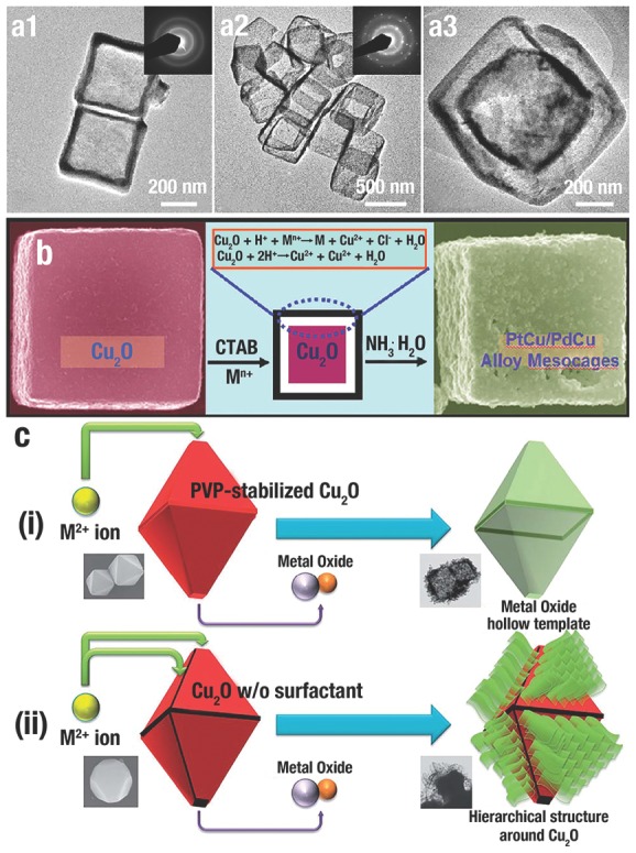
TEM images of a1) Fe(OH)x nanoboxes, a2) α‐Fe2O3 nanoboxes and a3) Fe(OH)x box‐in‐box structures. Inset of (a1) and (a2) is the corresponding SAED pattern. Reproduced with permission.49 Copyright 2010, American Chemical Society. b) Schematic illustration of the formation of noble metal alloy mesocages from c‐Cu2 O. Reproduced with permission.134 Copyright 2011, American Chemical Society. c) Schematic presentation of the i) PVP‐Cu2O and ii) non‐PVP‐Cu2O etching reaction behaviour by metal(II) ions. Reproduced with permission.166 Copyright 2013, Royal Society of Chemistry.
Galvanic replacement has facet selectivity when the surface of template possesses more than one type of facet.139 Similar to the etching process, galvanic replacement also begins with the facet(s) with the highest surface energy. Certainly, the surface energies of facets can also be altered and even reverse their order via the adsorption of CA.39 Using PVP to stabilize the {111} facets of Cu2O truncated octahedra, Y. S. Kang et al.166 obtained metal oxide hollow structures by controlling the galvanic replacement occurring on the {100} facets (Figure 9ci). In contrast, galvanic replacement and subsequent selective deposition would happen on the {111} facet of Cu2O crystals without the protection of PVP, leading to the formation of hierarchical structures (Figure 9cii).
5.2. The Kirkendall Effect
The Kirkendall effect is defined as the migration of the boundary layer between two materials when the two materials have different interdiffusion rates. Due to the faster diffusion rate, voids would be formed in the inner component, which is the most defining feature of the Kirkendall effect.39 Over the past decade, the Kirkendall effect has become a promising route for creating micro–nano materials with hollow structures.167, 168 Compared to the mono‐stoichiometric Cu2O, copper sulfides (CuxS) at room temperature possess at least five stable phases: i.e., chalcocite (Cu2S), djurlite (Cu1.95S), digenite (Cu1.8S), anilite (Cu1.75S), and covellite (CuS).93 Their unique electrical and optical properties derive from the valence states and complicated structures.93, 96 The Cu2O‐template route (Figure 8b) is a facile and straightforward by adding sulfur sources (i.e., Na2S solution, thioacetamide, and thiourea) into the Cu2O suspension, in which Cu2O template is transformed into Cu2O/CuxS core/shell structures at once because of the minimal solubility product constant K sp of CuxS (K sp ≈ 10−48).93 Finally, the Cu2O core is dissolved completely, and the CuxS shell is kept to the formation of hollow structures.
By using Cu2O crystals as templates, D. S. Xu et al.93 first created non‐spherical CuxS mesocages (including cubic, octahedral and multi‐pod) with single‐crystalline shells. Figure 10 a is a typical TEM image of cubic CuxS cages. Through a replacement reaction between S2− in solution and O in the Cu2O lattices, Cu2O/CuxS core/shell structures were firstly formed; CuxS mesocages obtained through a subsequently removing the residual Cu2O by ammonia. It is noteworthy that the compositions can be adjusted from Cu2S to Cu1.75S through controlling the reaction atmospheres from N2 to air as shown in Eq. (3) and Eq. (4), respectively.
| (3) |
| (4) |
Figure 10.
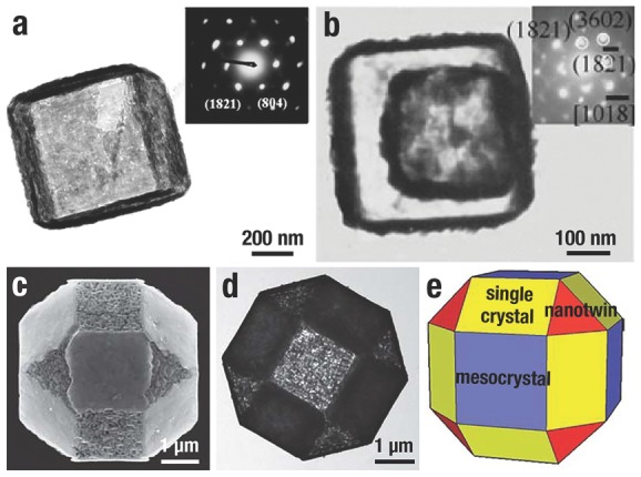
a) TEM image of CuxS cages. Inset of (a) is the SAED pattern of the CuxS cage. Reproduced with permission.93 b) TEM images of double‐walled Cu7S4 nanoboxes. Inset of (b) is the SAED pattern of the single nanobox. Reproduced with permission.160 Copyright 2009, Royal Society of Chemistry. c,d) SEM and TEM images of a individual 26‐facet Cu7S4 microcage, and e) the corresponding simulated structure. Reproduced with permission.161 Copyright 2011, Royal Society of Chemistry.
Guided by the above mechanisms, W. X. Zhang et al.160 synthesized double‐walled Cu7S4 nanoboxes by two consecutive cycles that repeatedly produced Cu7S4 layers in Na2S solution and dissolved the Cu2O core in NH3 solution (Figure 10b). Using polyhedral 26‐facet Cu2O microcrystals as the templates, S. D. Sun et al.161 synthesized 26‐facet CuS microcages with different types of shells (Figure 10c–e). Interestingly, the three pairs of square {100} facets and the four pairs of triangular {111} facets became rough with self‐assembled nanoplate, however, the six pairs of rectangular {110} facets remained smooth. Further TEM analysis demonstrated that the {100}, {111} and {110} facets of CuS microcage were transformed into mesocrystal, nano‐twin and single crystal, respectively colored blue, red, and yellow in the simulated structure shown in Figure 10e. The formation of different shells is attributed to the different crystallographic structures of {100}, {111} and {110} facets of Cu2O crystals. The {110} and {111} facets with dangling Cu atoms could be protected by negatively charged agents, while the neutral {100} facet had weak protection. Thus, the rate of the Kirkendall process between S and O atoms was different in each surface, leading to different shells.
5.3. Coordinating Eetching
Coordinating dissolution is commonly used for dissolving insoluble materials. For instance, by using certain ligands (CN−, SCN−, S2O3 2−, Cl− or NH3 etc.) coordinate Cu2O polyhedra, various transition metal hydroxides, or oxides with hollow structures could be obtained, perfectly imitating the geometry of the Cu2O template. Z. Y. Wang et al.48 synthesized uniform SnO2 nanoboxes by combining precisely controlled hydrolysis of SnCl4 and simultaneous coordinating etching of the c‐Cu2O templates. During this process, insoluble CuCl intermediate was immediately formed, and dissolved in NaCl solution via coordinating with excess Cl− to form soluble [CuClx]1−x. Eventually, outward evacuation of [CuClx]1−x and inward diffusion of Sn4+ and Cl− through the SnO2 shell lead to formation of intact SnO2 shells and the consumption of Cu2O templates. Based on the Pearson's hard and soft acid–base (HSAB) principle, stable complexes could be formed through the interaction of hard bases with hard acids, and soft bases with soft acids. As a soft acid, Cu+ within the Cu2O templates prefer a soft base ligand (S2O3 2−, CN−, SCN−) to a hard base (Cl−, NH3) as the coordinating etchant. Recently, our group47 put forward a general route to create metal hydroxides (MHs, M = Mn, Fe, Co, Ni, and Zn) nanocages by employing o‐Cu2O as the sacrificial template at room temperature.
| (5) |
| (6) |
| (7) |
The strategy was well designed by using Na2S2O3 as the coordinating etchant. S2O3 2− would coordinate etching Cu2O and form soluble [Cu2(S2O3)x]2−2x, because the soft−hard interaction of Cu+−O2− within Cu2O was weakened compared to the soft−soft interaction of Cu+−S2O3 2− (Eq. (5)). Due to the unstable interaction of borderline acid−soft base (M2+ − S2O3 2−), metal ions (M2+) were free in the solution. The OH− ions that originated from Cu2O etching (Eq. (5)) and some S2O3 2− hydrolysis (Eq. (6)) lead to the generation of M(OH)2 (Eq. (7)). The above routes could be concluded as “coordinating etching and precipitating”, which is shown as Step 1 in Figure 8c. The two simultaneous reactions ensure that the shell of M(OH)2 perfectly kept the original shape of o‐Cu2O (Step 2 in Figure 8c). Through simple thermal treatment, those polyhedral amorphous MHs nanocages could dehydrate into polycrystalline metal oxide (MO) porous nanocages (Step 3 in Figure 8c).
Well‐defined MH nanocages (Mn(OH)2, Fe(OH)2, Co(OH)2, Ni(OH)2, and Zn(OH)2) could be produced according the CEP route (Figure 11 ). The as‐prepared MH nanocages kept the shape of the o‐Cu2O template with an edge length of ≈500 nm (Figure 11 x 1; x = a–e), and small NPs consisted of the MH shell (Figure 11 x 2). TEM images of MH nanocages (Figure 11 x 3) clearly illustrated their hollow characteristic, and the SAED patterns (Figure 11 x 4) demonstrated their amorphous in nature. According to this strategy, amorphous Ni(OH)2 nanoboxes52 (Figure 12 a), Co(OH)2/reduced graphene oxide45 (Figure 12b) and Ni–Co amorphous double hydroxides35 (Figure 12c,d) can also be obtained by minor revised this method, and illustrate excellent performances in the realm of sensor and energy.
Figure 11.
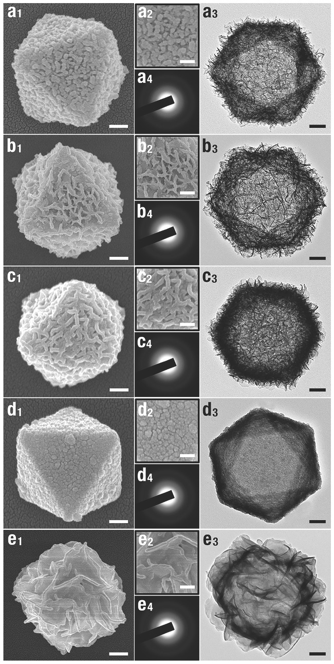
SEM, TEM, and SAED images of the a) Mn(OH)2, b) Fe(OH)2, c) Co(OH)2, d) Ni(OH)2, and e) Zn(OH)2 nanocages. Parts (x 1)(x = a–e) and (x 3) display typical SEM and TEM images of MH nanocages, respectively; part (x 2) displays high‐magnification SEM images of part (x 1); part (x 4) is the corresponding SAED patterns. The scale bars in parts (x 1), (x 2), and (x 3) are 100, 20, and 100 nm, respectively. Reproduced with permission.47 Copyright 2013, American Chemical Society.
Figure 12.
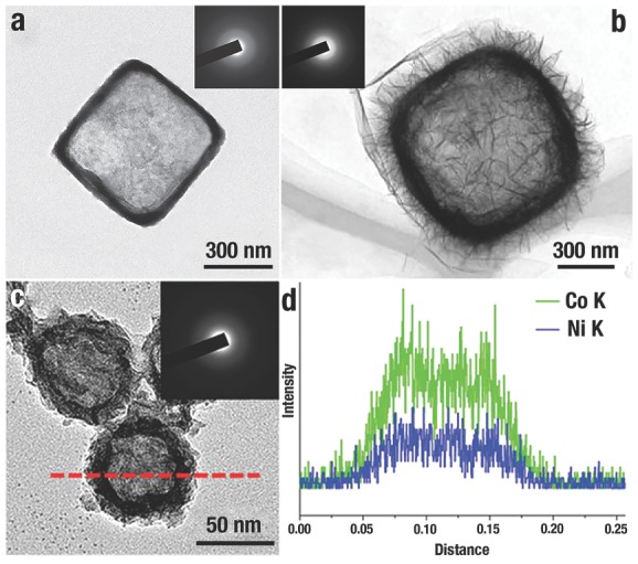
a) Typical TEM image of Ni(OH)2 nanobox with thin shell and well‐defined interior. Reproduced with permission.52 b) Typical TEM image of Co(OH)2/rGO with secondary structures. Reproduced with permission.45 Copyright 2014, American Chemical Society. c) A typical TEM image of NiCo2.7(OH)x double hydroxides nanocages, and d) their corresponding EDS measurements. Reproduced with permission.35 Inset of a–c) is the SAED pattern of each hydroxides nanocages.
6. Applications in Catalysis and Sensing
To date, the applications of Cu2O have mainly been in the realms of catalysis and sensing. In this section, we will focus on the facet‐dependent performances of the three basic Cu2O NCs and such Cu2O‐based NCs for applications of photocatalysis, gas catalysis, organocatalysis, and sensing as well as the relationship between their structures and properties.
6.1. Photocatalysis
The requirement of sustainable energy and reduction of environmental pollution has driven considerable research efforts in photo‐degradation of pollutants and water splitting by employing abundant solar energy.169 Cu2O with bandgap of 2.1 eV are expected to be promising materials in visible‐light photocatalytic degradation,69 and great studies have been devoted to the controlled synthesis of Cu2O with their morphology‐dependent photocatalytic activities.33, 36, 44, 73, 114, 147 During the photocatalytic process, one of the key factors for the catalyst is “catching” the organic pollutants, since that would offer the catalyst more opportunities to contact and catalyze those pollutants.44, 75 Our group7 demonstrated that the adsorption ability of methyl orange (MO), one of the industrial pollutants, to the different shapes of Cu2O NCs followed the sequence of octahedra > cubooctahedra > cubes. The exposed {111} facets of o‐Cu2O had positively charged “Cu” atoms that inclined to interact with the negatively charged groups –SO3 − in MO molecules. This suggested that Cu2O {111} facets would strongly interact with the molecules possessing negatively charged groups, and then effectively photodecompose these molecules; while the {111} facets interact weakly with the positively charged molecules, and lead to a poor photodegradation activities. As expected, M. H. Huang et al.128 verified that the photocatalytic activity of o‐Cu2O was higher than that of c‐Cu2O. Furthermore, the photocatalytic activities of extended hexapods Cu2O NCs with more {111} facets were more effective and active than o‐Cu2O (Figure 13 a). Subsequently, they synthesized d‐Cu2O NCs with only exposed {110} facets,75 which exhibited an excellent photocatalytic activities for the photodegradation of MO because of the high density of Cu atoms on the surface (Figure 13b). T. R. Zhang et al.135 demonstrated the photocatalytic activities of Cu2O microcrystals: c‐Cu2O with {100} facet <o‐Cu2O with {111} facet < 50‐facet polyhedral with {211} facet ≈ 50‐facet polyhedra with {522} facet ≈ 50‐facet polyhedral with {311} facet (Figure 13c). The larger number of atomic steps and kinks in these high‐index facets contributed to the more efficient photodegradation than those of the c‐Cu2O and o‐Cu2O.
Figure 13.
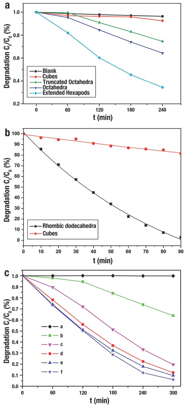
a) Degree of photodecomposition of MO vs time by using different Cu2O NCs as the photocatalysts. The blank sample only contain the MO solution without Cu2O NCs. Reproduced with permission.128 Copyright 2009, American Chemical Society. b) Degree of photodecomposition of MO vs time by using d‐Cu2O and c‐Cu2O as the photocatalysts. Reproduced with permission.75 Copyright 2012, American Chemical Society. c) Degree of photodecomposition of MO vs time by using different Cu2O Cu2O NCs as the photocatalysts: (a) blank sample; (b) c‐Cu2O; (c) o‐Cu2O; (d) 50‐facet polyhedra with {211}; (e) 50‐facet polyhedra with {522} and (f) 50‐facet polyhedra with {311}. Reproduced with permission.135 Copyright 2012, Royal Society of Chemistry.
A more efficient photogenerated electron–hole (e−/h+) pair separation would contribute to the improvement of photocatalytic activity. Besides the strong interaction between MO and the {111} corners and {110} edges of Cu2O jagged polyhedron (Figure 14 a,b), the OH− ions also selectively adsorb onto these corners and edges with higher energy. Thus, a faster e−/h+ separation will accelerate the production of the ·OH free radicals and then enhance their photocatalytic activities. Compared to the precursor of Cu2O truncated octahedron, the Cu2O jagged polyhedron displayed a better photocatalytic performance in the degradation of MO (Figure 14c).44 After 75 min, MO was only degraded to 60% by the Cu2O precursor, while MO was even degraded to 82% by jagged Cu2O.
Figure 14.
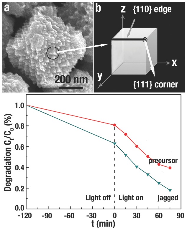
a,b) SEM image and illustration of the triangular pyramids of Cu2O jagged polyhedron. c) Degree of photodecomposition of MO vs time by using Cu2O precursor and jagged polyhedron as the photocatalysts. Reproduced with permission.44
Furthermore, another important factor for photodecomposition reactions is the rapid transportation to the surfaces of photogenerated charges. A Schottky barrier could be formed at the metal–semiconductor interface that reduces the recombination of the photogenerated e−/h+ pairs, and then improve photocatalytic efficiency.30, 33, 36 Y. J. Xiong et al.33 designed a p‐type metal–semiconductor (Pd–Cu2O) heterostructure, and demonstrated that the synergistic effect between charge spatial separation and Schottky barrier contributed to the efficient hydrogen production from pure water (Figure 15 ). Due to the low work function of {111} facet, no Schottky barrier is formed at the Pd–Cu2O{111} interface; instead, an anti‐blocking layer would be formed at that interface that increase the recombination of e−/h+ pairs (Figure 15a). In contrast, since the high work function of {100} facet, e−/h+ pairs would be well separated at the Cu2O{100}‐Pd interface (Figure 15b). The hydrogen production of Pd–Cu2O cubes with proper Pd load capacity over 4 h was 2.20 mmol g−1, which was dramatically higher than other Cu2O counterparts (Figure 15c).
Figure 15.
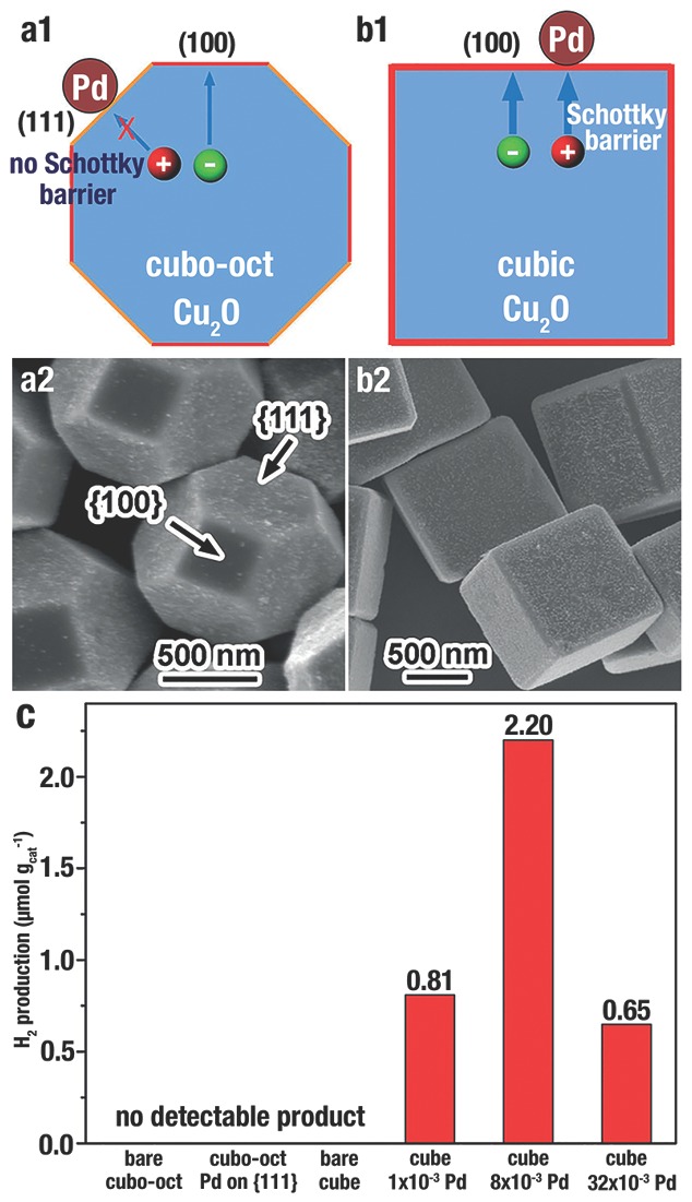
a1,b1) Scheme of the photogenerated charge transfer in the Pd‐Cu2O cubo‐octahedron and Pd‐Cu2O cubes, respectively. a2,b2) SEM image of Cu2O cubo‐octahedron and Cu2O cubes with Pd selectively loaded on the {111} and {100} surface, respectively. The molar ratio of Pd/Cu2O in b2 is 8 × 10⁻³. c) H2 production from pure water irradiation for 4 h by employing various photocatalysts under visible‐light (λ > 400 nm). “Cubo‐oct” denotes cubo‐octahedron, and the concentrations represent the molar ratio of Pd/Cu2O. Reproduced with permission.33
6.2. Gas Catalysis
Cu2O crystals have been actively studied in gas catalysis, and showed facet‐dependent catalytic performance.2, 3, 59, 170 W. X. Huang et al.2 evaluated the CO oxidation of uniform c‐Cu2O and o‐Cu2O. HRTEM images (Figure 16 a,b) demonstrated that the surfaces of c‐Cu2O and o‐Cu2O were all oxidized to CuO thin films during the CO oxidation (denoted as CuO/c‐Cu2O and CuO/o‐Cu2O, respectively). CuO/c‐Cu2O became active at 190 ºC and achieved a conversion rate of 49.1% CO at 240 ºC, while CuO/o‐Cu2O became active at 140 ºC and achieved the conversion rate of 93.2% CO at 240 ºC (Figure 16c). The activation energies of CuO/c‐Cu2O and CuO/o‐Cu2O oxidized CO were calculated to be 110.0 ± 6.4 and 73.4 ± 2.6 kJ mol−1 respectively, as shown in the Arrhenius plot of Figure 16d. Density functional theory (DFT) calculation suggested that CuO thin films grow on {111} and {100} facets with different surface compositions and structures (Figure 16e,f). Three‐coordinated O (O3c) and three‐coordinated Cu (Cu3c) atoms were terminated at the CuO overlayer on {111} facet (Figure 16e); by contrast, only O2c atoms were terminated at the {100} facet (Figure 16f).
Figure 16.
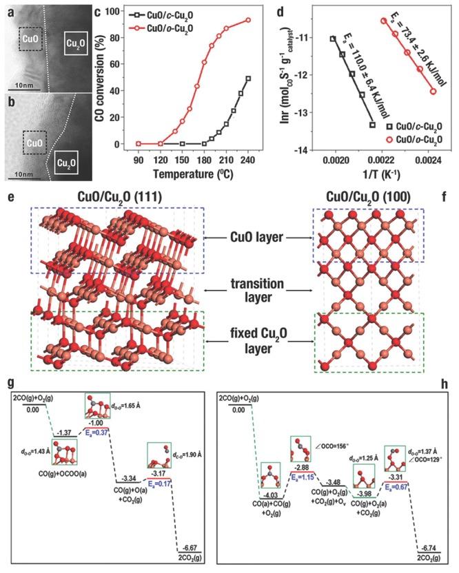
a,b) HRTEM image of CuO thin film formed on Cu2O cube (CuO/c‐Cu2O) and Cu2O octahedron (CuO/o‐Cu2O) during the CO oxidation, respectively. c) Catalytic performance of CuO/c‐Cu2O and CuO/o‐Cu2O in CO oxidation. d) The activation energies of CO oxidation catalyzed by CuO/c‐Cu2O and CuO/o‐Cu2O showed in the Arrhenius plot. Optimized surface structures of e) CuO/Cu2O {111} and f) CuO/Cu2O {100}, and the energy profiles of each elementary step in the oxidation of CO catalyzed by g) CuO/Cu2O {111} and h) CuO/Cu2O {100}. The grey, red and pink spheres denote C, O and Cu atoms, respectively. Reproduced with permission.2
Further DFT calculation results demonstrated that there were significant differences in the reaction process and active sites during the process of CuO/c‐Cu2O and CuO/o‐Cu2O oxidized CO (Figure 16g,h). For the surface of CuO/o‐Cu2O (Figure 16g), individual CO or O2 molecules were weakly adsorbed on the sites of Cu3c, while these two molecules could be strongly co‐adsorbed on the sites of O3c and Cu3c and then a OCOO(a) surface intermediate (SI) was formed. Subsequently, the OCOO(a) SI disintegrated into CO2 and a O(a) adatom, with an activation energy (Ea) of 0.37 eV. Finally, CO reacted with O(a) adatom to produce CO2 with a Ea of 0.17 eV; thus, a cycle of catalytic process has completed. For the surface of CuO/c‐Cu2O (Figure 16h), O2 molecules could not adsorb on the sites of O2c, while CO could be strongly adsorbed onto the sites of O2c and a CO3(a) SI was formed. Next, the CO3(a) SI disintegrated to generate CO2, and an oxygen vacancy (OV) was created in CuO with a Ea of 1.15 eV. Subsequently, O2 molecules could adsorb on OV in CuO to produce O2(a). Finally, CO reacted with O2(a) to produce CO2 with a Ea of 0.67 eV; thus, a cycle of catalytic process has completed, and the OV has refilled. Therefore, DFT calculation results were in accordance with experimental results, which demonstrated that CO oxidation catalyzed by CuO/o‐Cu2O proceeded with a lower Ea (the disintegration of the OCOO(a), 0.37 eV) than that catalyzed by CuO/c‐Cu2O (the disintegration of the CO3(a) SI, 1.15 eV).
W. X. Huang et al.3 further reported the facet‐dependent performances in catalyzing propylene oxidation by using CA‐free c‐Cu2O, o‐Cu2O, and d‐Cu2O. c‐Cu2O enclosed by {100} facets were most selective for CO2; o‐Cu2O exposed {111} facets were most selective for acrolein; d‐Cu2O enclosed by {110} facets were most selective for propylene oxide (Figure
17
a). All the three Cu2O NCs became active at 170 ºC, and the conversion rate of C3H6 rose with the increase of reaction temperature (Figure 17 b1‐b3). In addition, the efficiency of C3H6 conversion was followed the order o‐Cu2O > c‐Cu2O > d‐Cu2O. The specific reaction rate of propylene for various Cu2O NCs also followed the order o‐Cu2O > c‐Cu2O > d‐Cu2O (Figure 17 b4). o‐Cu2O are more active in catalyzing C3H6 oxidation with O2 than c‐Cu2O and d‐Cu2O. The (111) plane was terminated with three‐coordinated unsaturated O (OCUS) in the first layer, and one‐coordinated unsaturated Cu (CuCUS) and coordinated saturated (CuCSA ) in the second layer in a 1:3 ratio. The (100) plane was terminated with two‐coordinated OCUS in the first layer, and CuCSA in the second layer. The (110) plane was terminated with three‐coordinated OCUS and CuCSA in the first layer, and CuCSA in the second layer. DFT calculations explained the adsorption of C3H6 on (111), (100), and (110) facets (Figure 17b). For the (111) facet (Figure 17c), CuCUS–C3H6(a) was formed through the selective adsorption of C3H6 molecules at the site of CuCUS (C=C stretching frequency ( ) of 1560 cm−1) with an adsorption energy (Eads) of –1.53 eV. For the (100) facet (Figure 17c), OCUS,OCUS–C3H6(a) was formed through the selective adsorption of C3H6 molecules at the site of two neighboring two‐coordinated OCUS (
 = 1453 cm−1) with an Eads of –2.85 eV. For the (110) facet (Figure 17c), C3H6 adsorbed on the three‐coordinated OCUS, and CuCSA sites to form CuCSA,OCUS–C3H6(a) (
 = 1437 cm−1), and on OCUS site to generate OCUS–C3H6(a) (
 = 1574 cm−1). The Eads for the two sites of (110) facet was similar.
Figure 17.
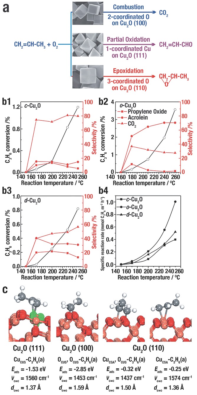
a) Scheme of facet‐dependent selectivity of Cu2O catalysed propylene oxidation with O2. b1–b3) The conversion of C3H6 and selectivity of the C3H6 oxidation with O2 for propylene oxide, acrolein, and CO2 catalysed by: b1) c‐Cu2O, b2) o‐Cu2O, and b3) d‐Cu2O. b4) Specific reaction rate of the oxidation of C3H6 with O2 catalysed by c‐Cu2O, o‐Cu2O, and d‐Cu2O. c) The most stable structures of C3H6(a) species on Cu2O (111), (100), and (110) facet with the adsorption energy (Eads), C=C stretching frequency, and distance of C=C bond (d C=C). White, red, gray, green and pink balls behalf H, O, C, coordinatively unsaturated Cu, and coordinatively saturated Cu, respectively. Reproduced with permission.3
In addition, different SI produced on each Cu2O NCs. On the Cu2O (111) surface, the distance of C=C bond (d C=C) in CuCUS–C3H6(a) was calculated to be 1.37 Å, while d C=C in C3H6 molecule was 1.34 Å. Therefore, the stable C=C bond of CuCUS–C3H6(a) can be kept in the subsequent reactions, which was in favor of the generation of acrolein. On the Cu2O(100) surface, dC=C in OCUS,OCUS–C3H6(a) was 1.59 Å; hence, the weakened C=C bond would be cleaved by propylene combusting. DFT calculation results (Figure 18 a) demonstrated that the Ea for the combustion of OCUS, OCUS–C3H6(a) to adsorb C3H6O(a) and the disintegration of OCUS, OCUS–C3H6(a) into adsorbed CH2(a) and CHCH3(a) was 2.09 and 1.02 eV, respectively. This result suggested that propylene was in favor of combustion, which was in accordance with the experiments of c‐Cu2O. On the Cu2O(110) surface, d C=C in OCUA–C3H6(a) was 1.36 Å, which was considered to the generation of acrolein; while the weakened C=C bond in CuCSA,OCUS–C3H6(a) with a distance of 1.50 Å inclined to break during the reactions. DFT calculations results (Figure 18b) suggested that the Ea for the combustion of OCUA,OCUS–C3H6(a) to adsorb C3H6O(a) and the disintegration of OCUA,OCUS–C3H6(a) into adsorbed CH2(a) and CHCH3(a) was 1.28 and 2.08 eV, respectively. This result suggested that propylene was in favor of epoxidation, which was in accordance with the experiments of d‐Cu2O. The distinction in reactivities between CuCSA,OCUS–C3H6(a) on Cu2O(110) and OCUS,OCUS–C3H6(a) on Cu2O(100) is three‐coordinated OCUS on (110) facet and two‐coordinated OCUS on (100) facet. Three‐coordinated OCUS is less electrophilic than two‐coordinated OCUS, which is to the disadvantage of the breakage of the C=C bond in propylene.
Figure 18.
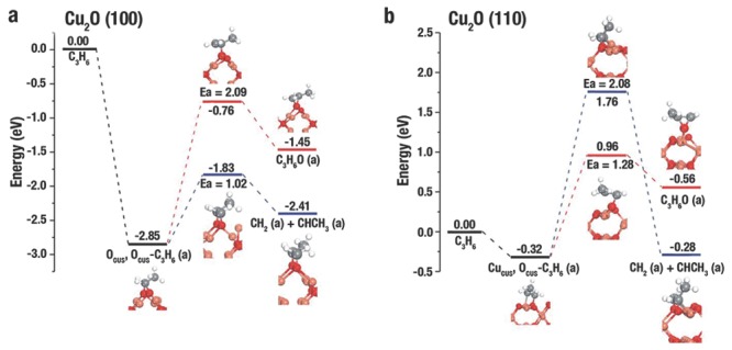
The potential energy surface and corresponding structures for epoxidation and the complete C=C bond breaking of adsorbed propylene on a) Cu2O(100) and b) Cu2O(110). Pink, red, white, and gray balls represent Cu, O, H, and C atoms, respectively. Reproduced with permission.3
Compared to low‐index facets, the high‐index facets have higher catalytic activities due to the more atomic steps and kinks. C. Wang et al.17 evaluated the CO oxidation of a series of Cu2O polyhedra. Due to the presence of high‐index {311} planes on their surfaces, the 50‐facet Cu2O microcrystal showed the highest specific catalytic rate (8.8 × 10⁻⁶ mol m−2 cat s−1), which was markedly higher than d‐Cu2O, o‐Cu2O, c‐Cu2O and rhombicuboctahedron (Figure 19 a). Z. X. Xie et al.121 investigated the CO oxidation of truncated concave o‐Cu2O enclosed mainly by high‐index surfaces {332} facets with high‐density atomic steps (Figure 19b, inset). Truncated concave o‐Cu2O {332} + {100} displayed the highest catalytic activity, which became active at 170 °C and reached a CO conversion rate of 50.4% at 220 °C. Truncated o‐Cu2O {111} + {100} became active at 170 °C with a lower CO conversion, and reached a CO conversion of 39.8% at 220 °C. However, c‐Cu2O illustrated the lowest catalytic activity that c‐Cu2O only became active at 190 °C and reached a CO conversion of 31.9% at 220 °C (Figure 19b).
Figure 19.
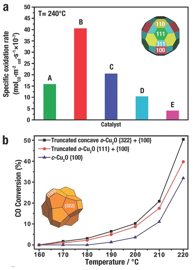
a) The specific oxidation rates of CO catalysed by different Cu2O polyhedra A) rhombicuboctahedron, B) Cu2O 50‐facet, C) d‐Cu2O, D) o‐Cu2O, and E) c‐Cu2O at 240 °C. Reproduced with permission.17 Copyright 2010, American Chemical Society. b) CO conversion of Cu2O microcrystals of different shapes. Reproduced with permission.121 Copyright 2013, Royal Society of Chemistry.
6.3. Organocatalysis
Numerous important products (optical devices, drugs, materials, etc.) commercialized or in the stage of development, have aromatic C—N and aromatic C—C bonds that can be coupled by organocatalysts through cross‐coupling reactions.171 Thus, scaling up production of these bonds with any novel and basic technology is greatly significant for industry.171 Over the last decade, the research focus on coupling of C—N and C—C bonds has gradually moved from the high‐cost Pd‐catalyst to the low‐cost Cu‐catalyst.172, 173 Recently, Cu2O (NC form or bulk) has been reported as excellent catalysts for cross‐coupling reactions.14, 24, 32, 40, 66 The facet‐dependent organocatalysis activity of c‐Cu2O, o‐Cu2O, and d‐Cu2O NCs was firstly evaluated by M. H. Huang et al.24 based on the synthesis of 1,2,3‐triazoles14 and the regioselective synthesis of 3,5‐disubstituted isoxazoles.24 To compare the catalytic activities of each Cu2O NCs, all the three NCs were used with identical surface area (Table 1 ). d‐Cu2O displayed the most efficient catalytic activity, with shortest reaction times and the highest product yields, followed by o‐Cu2O and the least active c‐Cu2O. These results demonstrate that delicate facet controlling of Cu2O NCs can greatly improve the organocatalytic efficiency. Subsequently, M. H. Huang et al.32 developed a capping‐free synthetic approach for the synthesis of sub‐100 nm Cu2O NCs with morphology evolution from c‐Cu2O to o‐Cu2O. All the Cu2O NCs illustrated high yields within short reaction times. o‐Cu2O was the most excellent catalyst that could catalyse the cycloaddition reaction in just 2 h with high yields.
Table 1.
The catalytic abilities of Cu2O NCs for the synthesis of 3‐(4‐nitrophenyl)‐5‐phenylisoxazolea

L. L. Li et al.66 employed monodisperse c‐Cu2O, d‐Cu2O, and octadecahedra to catalyse aerobic oxidative coupling of phenylacetylene and arylboronic acids. During the catalytic reaction, those NCs showed high yields but different crystal surface stability. After three catalytic cycles, c‐Cu2O were seriously etched and aggregated beyond recognition, as well as their yield dropping from 94% to 32%. By contrast, no change was observed in the {110} facets of d‐Cu2O and octadecahedra during the reaction. Interestingly, Cu2O octadecahedra had the best catalytic activity upon recycling, and the yield of aerobic oxidative coupling was increased from 89% to 97%. The reason was that the {100} facets of Cu2O octadecahedra were more prone to etching than the {110} facets during this catalytic reaction, and the Cu2O octadecahedra were gradually oxidized and etched to high‐active concaves (Figure 20 a). However, the in‐depth etching mechanism still requires further study. A metal–metal oxide interface formed after deposition of noble metal onto metal oxide, and the hybrid structure displayed superior catalytic performances to the physical mixtures or single domains.30, 33, 36, 40, 50, 145 L. L. Li et al.40 further improved the experimental route by selective depositing noble metals on the concave Cu2O NCs. Pd atoms only grew on cavities (Figure 20b, inset), but Ag0 majorly nucleated on edges and vertices (Figure 20c, inset). During the aerobic oxidative arylation of phenylacetylene, the hybrid nanoconcaves exhibited more excellent catalytic activities than the single component or physical mixtures (Figure 20b,c). XPS spectra combined DFT calculation results verified the improvement of catalytic activities attributed to the synergistic effect, in which e− migrated from the noble metal to Cu2O.
Figure 20.
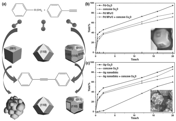
a) Shape evolution of the three different Cu2O NCs during the aerobic oxidative arylation of phenylacetylene. Reproduced with permission.66 Catalytic activities of b) Pd‐Cu2O and c) Ag‐Cu2O nanoconcave in the aerobic oxidative arylation of phenylacetylene. Inset of (b) and (c) is the typical SEM images of Pd‐Cu2O and Ag‐Cu2O, respectively. Reproduced with permission.40
6.4. Sensing
H. C. Zeng et al.8 evaluated the ethanol sensing ability of Cu2O self‐assembled 3D superlattices (≈10 nm) and disassembled nanocubes (≈20 nm), and the corresponding TEM images were shown in Figure 21 a, b, respectively. The organized Cu2O illustrated a better sensing capability than the disassembled Cu2O (Figure 21c). Without ethanol molecules, the defects on the surface of Cu2O would adsorb O2 from air and negatively charged O−, O2 −, and O2− are produced. A localized accumulation of holes were formed that separated from e− near the surfaces of Cu2O. When Cu2O was exposed to ethanol/air mixtures, e− was produced from the redox reactions between adsorbed O2 on the surface and ethanol that would be transferred into conduction band of Cu2O. And then, e− and h+ would be recombined that lead to decrease the concentration of carrier. Due to the higher ratio of surface to bulk, a greater carrier depletion layer would be formed of the self‐assembled c‐Cu2O when exposed to ethanol. That layer, in cooperation with a relatively small contact potential, would result in a distinct improvement of sensitivity (Figure 21d).
Figure 21.
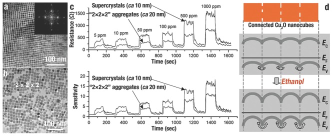
TEM images of a) Cu2O self‐assembled 3D supercrystals and b) disassembled nanocubes. c) Their corresponding sensitivities toward ethanol sensing measured under identical situations. d) The schematic diagrams of 1D array of c‐Cu2O toward ethanol sensing, where E F, E V, and E C are Fermi energy, valence band energy, and conduction band energy, respectively. Reproduced with permission.8 Copyright 2010, American Chemical Society.
Our group60 evaluated the CO sensing performance of Cu2O–CuO composite microframes at the working temperature of 240 ºC. As the concentration of CO increased, the Cu2O–CuO composite microframes illustrated excellent CO sensing performance with highest sensitivity and shortest response time, followed by the pure CuO microcubes and the pure Cu2O microcubes (Figure 22 ).
Figure 22.
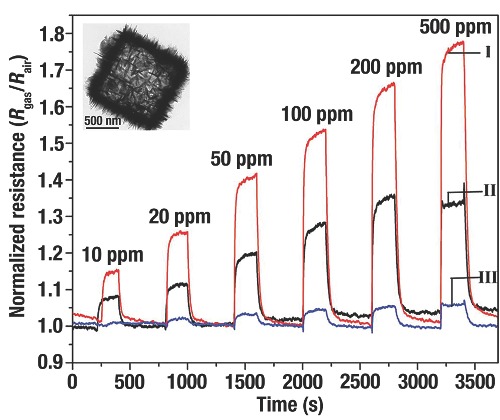
The normalized resistance of CO exposure on (I) Cu2O‐CuO microframes, (II) pure CuO cubes and (III) pure Cu2O cubes. Inset is a typical TEM image of the Cu2O‐CuO microframe. Reproduced with permission.60 Copyright 2013, Royal Society of Chemistry.
In the presence of o‐anisidine and graphene oxide, H. M. Fan et al.81 synthesized reduced graphene oxide (rGO)–conjugated Cu2O nanowire (NW) composite mesocrystals. The obtained mesocrystals with marked octahedral shape and eight {111} facets were composed of highly oriented nanowires. They further compared the NO2 sensing performance of Cu2O NW, rGO and rGO–Cu2O mesocrystals at room temperature. In the presence of NO2, all the three samples exhibited an increased sensitivity with the increasing concentration of NO2 (Figure 23 a,b). The sensitivities of rGO–Cu2O, Cu2O NW, and rGO at 2.0 ppm were 67.8%, 44.5%, and 22.5%, respectively. And the limits of detection (LOD) were calculated as 64, 81, and 82 ppb for rGO–Cu2O, Cu2O NW, and rGO, respectively. The improved sensing performance of the rGO–Cu2O mesocrystals was attributed to their high specific surface area and enhanced conductivity. When rGO–Cu2O was exposed to NO2, the NO2 molecule could obtain e− from the “activated” surface O ion, and the rGO with excellent electrical conductivity could effectively transfer electrons that promoted the h+ conductivity in the Cu2O (Figure 23c). Furthermore, because of the porous and highly anisotropic structure of NW mesocrystals cooperated with the rGO, the rGO–Cu2O possessed larger surface accessibility for contacting NO2.
Figure 23.
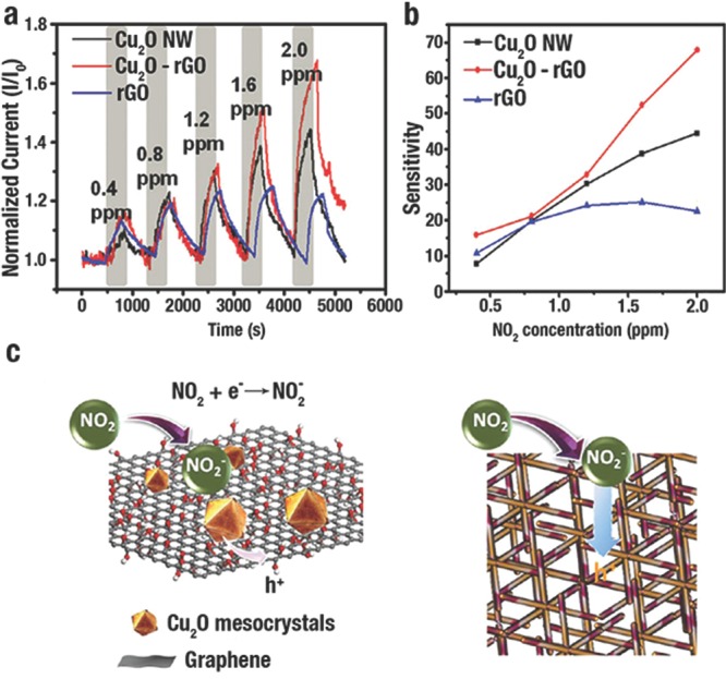
a) Response of Cu2O NW, rGO‐Cu2O, and rGO with the increasing concentration of NO2. b) The sensitivities for detection of NO2 on Cu2O NW, rGO‐Cu2O, and rGO. c) The mechanism of rGO‐Cu2O toward NO2 sensing. Reproduced with permission.81 Copyright 2012, American Chemical Society.
Recently, S. H. Yu et al.29 investigated the facet‐dependent stripping behaviour in the determination of Pb2+ by using c‐Cu2O, o‐Cu2O, and d‐Cu2O through square wave stripping voltammetry (SWASV). At –0.65 V, all three samples illustrated sharp stripping peaks of Pb2+ with different detection limit and sensitivity (Figure 24 a). The o‐Cu2O modified electrode illustrated the lowest detection limit of 0.066 × 10⁻⁶ M (Figure 24a2) and highest sensitivity of 178 ± 20.3 μA μm−1 cm−2 (Figure 24a4), followed by c‐Cu2O of 0.076 × 10⁻⁶ M (Figure 24a1) and 127 ± 14.4 μA μm−1 cm−2 (Figure 24a4), and d‐Cu2O of 0.103 × 10⁻⁶ M (Figure 24a3) and 90.1 ± 13.4 μA μm−1 cm−2 (Figure 24a4). It suggested that the order of stripping response of Pb2+ on Cu2O microcrystal facets was found to follow the sequence {111} > {100} > {110}.
Figure 24.
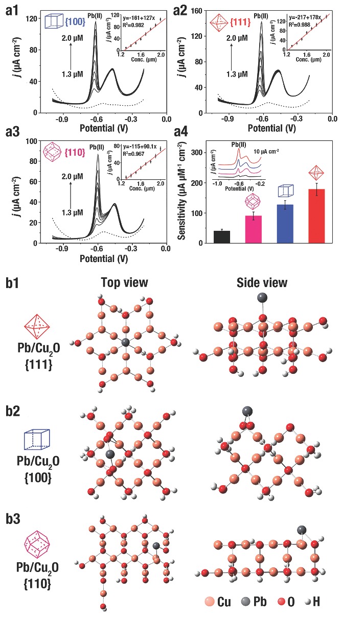
a1–a4) Typical SWASV responses of a1) c‐Cu2O, a2) o‐Cu2O, and a3) d‐Cu2O to detect Pb(II) in optimal situations. The corresponding linear fitting was inset in (a1), (a2) and (a3), respectively. a4) Sensitivities for SWASV detection of Pb(II) on bare GCE, d‐Cu2O, c‐Cu2O, and o‐Cu2O modified GCE. Inset of (a4) shows SWASV responses of 1.4 × 10⁻⁶ m Pb(II) on bare GCE (black line), o‐Cu2O (red line), c‐Cu2O (blue line), and d‐Cu2O (pink line) modified GCE. b1–b3) Top and side views of optimized adsorption models of Pb(II) on different Cu2O NCs simulated by DFT. Reproduced with permission.29
DFT calculations were employed to investigate the adsorption mechanism of Pb2+ on Cu2O. Figure 24b depicted the conditions of Pb2+ adsorption on different Cu2O surfaces. When Pb2+ adsorbed on {111} surface (Pb/Cu2O {111}) (Figure 24b1), one O atom coordinated with Pb2+, and the distance of Pb–O bond was 2.188 Å. When for the {100} surface (Figure 24b2), two O atoms coordinated with Pb2+, and the distance of Pb–O bond was 2.260 and 2.223 Å. Figure 24b3 showed the Pb/Cu2O {110} that one Cu atom and one O atom coordinated with Pb2+, because the Cu and O atoms were in the identical plane in top layer, and the distances of Pb–Cu and Pb–O bond were 2.685 Å and 2.183 Å. The shorter distance of Pb–O in Pb/Cu2O {111} contributed to the strong adsorption with the Cu2O surface. Furthermore, the adsorption Gibbs free energy of Pb(II) on {100}, {110} and {111} facets were calculated as 4.952, 4.761 and 5.742 eV, respectively. These calculated results demonstrate the stronger Pb2+ adsorption ability of {111} facet, followed by the {100} and {110} facet, which agreed quite well with the electrochemical performance.
7. Conclusion and outlook
Through numerous examples, we have demonstrated that facet‐controlled synthetic strategies provide remarkably facile and convenient approaches to the preparation of Cu2O‐based NCs with heterogeneous, etched, or hollow structures. These routes depend on the different surface atomic structure of Cu2O NCs, in which the selective adsorption of CAs could protect special facets, and the surface energy and active sites would determine the reaction activity trend. The facet‐dependent properties of the Cu2O NCs and such Cu2O‐based NCs have been investigated, especially in the realm of photocatalysis, gas catalysis, organocatalysis and sensing. Due to different crystal surface structures, the Cu2O NCs exhibit distinct facet‐dependent properties; a subsequently rational design and synthesis of Cu2O‐based NCs could tailor and optimize their facet‐dependent performances. Although the controllable synthesis of NCs and their derivatives has seen considerable progress and development in the last decade, the next requirements for NCs with excellent performance are the development of more simple and convenient synthetic routes to tailor NCs with ideal components and structures.
The progress we have summarized also opens the door for in‐detail studies in catalysis and sensing. Due to their well‐defined facets, shape‐controlled NCs can provide smooth surfaces for further delicate carving, modifying, or transforming; a deep insight into the relationship between structures and properties will be obtained by combining with theoretical calculations and simulations of the catalysis and sensing process. This perception will enable further delicate tailoring of NCs, and bridge the gap between structures and properties, so that traditional trial‐and‐error pattern to obtain functional NCs would be instead replaced by ingenious design and controllable synthesis.
Finally, it is should be envisaged that the facet‐dependent properties of Cu2O‐based NCs could also apply to other realms. For instance, our group92 found that o‐Cu2O NCs displayed a higher oxidative stress to D. magna than that of c‐Cu2O due to its higher reactivity. M. H. Huang et al.9 investigated the facet‐dependent electrical properties of the three basic Cu2O NCs. o‐Cu2O is highly conductive, c‐Cu2O is moderately conductive, and d‐Cu2O is nonconductive. A thin surface layer having different degrees of band bending contributed to the different conductivities. Interestingly, a diode‐like response was obtained when electrical connection was made on two different facets of a rhombicuboctahedron. D. F. Xue et al.25 evaluated Li‐ion battery anode performances and showed that c‐Cu2O had the highest capacity among Cu2O polyhedra (the sequence of electroactivity is {110} < {111} < {100}), because {100} facets had high electroactivities toward redox reactions. Thus, more instances of the facet‐dependent properties should be continuously explored, endowing nanomaterials with excellent performances for numerous applications.
Acknowledgements
This project is supported by the National Basic Research Program of China (2014CB931802), the National Natural Science Foundation of China (51272012, 21471013) and China Postdoctoral Science Foundation Funded Project (2015M570916).
Biographies
Yang Shang was born in Beijing, China in 1986. He received his Ph.D. in Materials Science and Engineering from Beihang University under the supervision of Prof. Lin Guo in 2015. Since then, he has worked as a postdoctoral in Prof. Lin Guo's group. His research interests focus on controlled synthesis of copper and copper‐compound micro–nano materials for applications in catalysis and sensing.

Lin Guo received his Ph.D. in Materials Science and Engineering from Beijing Institute of Technology in 1997. He joined Beihang University in 2000 and now is Professor and Vice Dean at the School of Chemistry and Environment in Beihang University. His research interests include development of novel strategies to design functional micro–nano materials for catalysis and energy applications.
Shang Y. Guo L. (2015). Facet‐Controlled Synthetic Strategy of Cu2O‐Based Crystals for Catalysis and Sensing. Adv. Sci., 2: 1500140. doi: 10.1002/advs.201500140
References
- 1. Burda C., Chen X., Narayanan R., El‐Sayed M. A., Chem. Rev. 2005, 105, 1025. [DOI] [PubMed] [Google Scholar]
- 2. Bao H., Zhang W., Hua Q., Jiang Z., Yang J., Huang W., Angew. Chem. Int. Ed. 2011, 50, 12294. [DOI] [PubMed] [Google Scholar]
- 3. Hua Q., Cao T., Gu X. K., Lu J., Jiang Z., Pan X., Luo L., Li W. X., Huang W., Angew. Chem. Int. Ed. 2014, 53, 4856. [DOI] [PubMed] [Google Scholar]
- 4. Huang M. H., Rej S., Hsu S.‐C., Chem. Commun. 2014, 50, 1634. [DOI] [PubMed] [Google Scholar]
- 5. Liu G., Jimmy C. Y., Lu G. Q. M., Cheng H.‐M., Chem. Commun. 2011, 47, 6763. [DOI] [PubMed] [Google Scholar]
- 6. Li R., Han H., Zhang F., Wang D., Li C., Energy Environ. Sci. 2014, 7, 1369. [Google Scholar]
- 7. Zhang D.‐F., Zhang H., Guo L., Zheng K., Han X.‐D., Zhang Z., J. Mater. Chem. 2009, 19, 5220. [Google Scholar]
- 8. Yao K. X., Yin X. M., Wang T. H., Zeng H. C., J. Am. Chem. Soc. 2010, 132, 6131. [DOI] [PubMed] [Google Scholar]
- 9. Tan C.‐S., Hsu S.‐C., Ke W.‐H., Chen L.‐J., Huang M. H., Nano Lett. 2015, 15, 2155. [DOI] [PubMed] [Google Scholar]
- 10. Huang M. H., Lin P. H., Adv. Funct. Mater. 2012, 22, 14. [Google Scholar]
- 11. Zhou K., Li Y., Angew. Chem. Int. Ed. 2012, 51, 602. [DOI] [PubMed] [Google Scholar]
- 12. Wang H., Gao J., Guo T., Wang R., Guo L., Liu Y., Li J., Chem. Commun. 2012, 48, 275. [DOI] [PubMed] [Google Scholar]
- 13. Wang Y., Zhang H., Han Y., Liu P., Yao X., Zhao H., Chem. Commun. 2011, 47, 2829. [DOI] [PubMed] [Google Scholar]
- 14. Chanda K., Rej S., Huang M. H., Chem. Eur. J. 2013, 19, 16036. [DOI] [PubMed] [Google Scholar]
- 15. Wang H., Lang X., Gao J., Liu W., Wu D., Wu Y., Guo L., Li J., Chem. Eur. J. 2012, 18, 4620. [DOI] [PubMed] [Google Scholar]
- 16. Wang H., Yang J., Li X., Zhang H., Li J., Guo L., Small 2012, 8, 2802. [DOI] [PubMed] [Google Scholar]
- 17. Leng M., Liu M., Zhang Y., Wang Z., Yu C., Yang X., Zhang H., Wang C., J. Am. Chem. Soc. 2010, 132, 17084. [DOI] [PubMed] [Google Scholar]
- 18. Zhou Z.‐Y., Tian N., Li J.‐T., Broadwell I., Sun S.‐G., Chem. Soc. Rev. 2011, 40, 4167. [DOI] [PubMed] [Google Scholar]
- 19. Jiang Z.‐Y., Kuang Q., Xie Z.‐X., Zheng L.‐S., Adv. Funct. Mater. 2010, 20, 3634. [Google Scholar]
- 20. Jiang H. B., Cuan Q., Wen C. Z., Xing J., Wu D., Gong X.‐Q., Li C., Yang H. G., Angew. Chem. Int. Ed. 2011, 50, 3764. [DOI] [PubMed] [Google Scholar]
- 21. Yin J., Yu Z., Gao F., Wang J., Pang H., Lu Q., Angew. Chem. Int. Ed. 2010, 49, 6328. [DOI] [PubMed] [Google Scholar]
- 22. Han X., Jin M., Xie S., Kuang Q., Jiang Z., Jiang Y., Xie Z., Zheng L., Angew. Chem. Int. Ed. 2009, 48, 9180. [DOI] [PubMed] [Google Scholar]
- 23. Wang X., Han X., Xie S., Kuang Q., Jiang Y., Zhang S., Mu X., Chen G., Xie Z., Zheng L., Chem. Eur. J. 2012, 18, 2283. [DOI] [PubMed] [Google Scholar]
- 24. Chanda K., Rej S., Huang M. H., Nanoscale 2013, 5, 12494. [DOI] [PubMed] [Google Scholar]
- 25. Chen K., Song S., Xue D., CrystEngComm 2015, 17, 2110. [Google Scholar]
- 26. Fan W., Shi Z., Yang X., Cui M., Wang X., Zhang D., Liu H., Guo L., Water Res. 2012, 46, 5981. [DOI] [PubMed] [Google Scholar]
- 27. Li R., Zhang F., Wang D., Yang J., Li M., Zhu J., Zhou X., Han H., Li C., Nat. Commun. 2013, 4, 1432. [DOI] [PubMed] [Google Scholar]
- 28. Liu X.‐W., Langmuir 2011, 27, 9100. [DOI] [PubMed] [Google Scholar]
- 29. Liu Z.‐G., Sun Y.‐F., Chen W.‐K., Kong Y., Jin Z., Chen X., Zheng X., Liu J.‐H., Huang X.‐J., Yu S.‐H., Small 2015, 11, 2493. [DOI] [PubMed] [Google Scholar]
- 30. Long R., Mao K., Gong M., Zhou S., Hu J., Zhi M., You Y., Bai S., Jiang J., Zhang Q., Wu X., Xiong Y., Angew. Chem. Int. Ed. 2014, 53, 3205. [DOI] [PubMed] [Google Scholar]
- 31. Lyu L.‐M., Huang M. H., J. Phys. Chem. C 2011, 115, 17768. [Google Scholar]
- 32. Tsai Y.‐H., Chanda K., Chu Y.‐T., Chiu C.‐Y., Huang M. H., Nanoscale 2014, 6, 8704. [DOI] [PubMed] [Google Scholar]
- 33. Wang L., Ge J., Wang A., Deng M., Wang X., Bai S., Li R., Jiang J., Zhang Q., Luo Y., Xiong Y., Angew. Chem. Int. Ed. 2014, 53, 5107. [DOI] [PubMed] [Google Scholar]
- 34. Yang H. G., Sun C. H., Qiao S. Z., Zou J., Liu G., Smith S. C., Cheng H. M., Lu G. Q., Nature 2008, 453, 638. [DOI] [PubMed] [Google Scholar]
- 35. Nai J., Yin H., You T., Zheng L., Zhang J., Wang P., Jin Z., Tian Y., Liu J., Tang Z., Guo L., Adv. Energy Mater. 2015, 5, 1401880. [Google Scholar]
- 36. Bai S., Ge J., Wang L., Gong M., Deng M., Kong Q., Song L., Jiang J., Zhang Q., Luo Y., Xie Y., Xiong Y., Adv. Mater. 2014, 26, 5689. [DOI] [PubMed] [Google Scholar]
- 37. Li R., Hu J., Deng M., Wang H., Wang X., Hu Y., Jiang H.‐L., Jiang J., Zhang Q., Xie Y., Xiong Y., Adv. Mater. 2014, 26, 4783. [DOI] [PubMed] [Google Scholar]
- 38. Wang Z., Lou X. W., Adv. Mater. 2012, 24, 4124. [DOI] [PubMed] [Google Scholar]
- 39. Xia X., Wang Y., Ruditskiy A., Xia Y., Adv. Mater. 2013, 25, 6313. [DOI] [PubMed] [Google Scholar]
- 40. Li L., Chen X., Wu Y., Wang D., Peng Q., Zhou G., Li Y., Angew. Chem. Int. Ed. 2013, 52, 11049. [DOI] [PubMed] [Google Scholar]
- 41. Lim B., Xia Y., Angew. Chem. Int. Ed. 2011, 50, 76. [DOI] [PubMed] [Google Scholar]
- 42. Sui Y., Fu W., Zeng Y., Yang H., Zhang Y., Chen H., Li Y., Li M., Zou G., Angew. Chem. Int. Ed. 2010, 49, 4282. [DOI] [PubMed] [Google Scholar]
- 43. Yu H.‐D., Regulacio M. D., Ye E., Han M.‐Y., Chem. Soc. Rev. 2013, 42, 6006. [DOI] [PubMed] [Google Scholar]
- 44. Shang Y., Sun D., Shao Y., Zhang D., Guo L., Yang S., Chem. Eur. J 2012, 18, 14261. [DOI] [PubMed] [Google Scholar]
- 45. Guan X., Nai J., Zhang Y., Wang P., Yang J., Zheng L., Zhang J., Guo L., Chem. Mater. 2014, 26, 5958. [Google Scholar]
- 46. Chen J. S., Zhu T., Yang X. H., Yang H. G., Lou X. W., J. Am. Chem. Soc. 2010, 132, 13162. [DOI] [PubMed] [Google Scholar]
- 47. Nai J., Tian Y., Guan X., Guo L., J. Am. Chem. Soc. 2013, 135, 16082. [DOI] [PubMed] [Google Scholar]
- 48. Wang Z., Luan D., Boey F. Y. C., Lou X. W., J. Am. Chem. Soc. 2011, 133, 4738. [DOI] [PubMed] [Google Scholar]
- 49. Wang Z., Luan D., Li C. M., Su F., Madhavi S., Boey F. Y. C., Lou X. W., J. Am. Chem. Soc. 2010, 132, 16271. [DOI] [PubMed] [Google Scholar]
- 50. Zahran E. M., Bedford N. M., Nguyen M. A., Chang Y.‐J., Guiton B. S., Naik R. R., Bachas L. G., Knecht M. R., J. Am. Chem. Soc. 2014, 136, 32. [DOI] [PubMed] [Google Scholar]
- 51. Chen X., Liu L., Peter Y. Y., Mao S. S., Science 2011, 331, 746. [DOI] [PubMed] [Google Scholar]
- 52. Nai J., Wang S., Bai Y., Guo L., Small 2013, 9, 3147. [DOI] [PubMed] [Google Scholar]
- 53. Zhang L., Wang H., ACS Nano 2011, 5, 3257. [DOI] [PubMed] [Google Scholar]
- 54. Huang M. H., Rej S., Chiu C.‐Y., Small 2015, 11, 2716. [DOI] [PubMed] [Google Scholar]
- 55. Susman M. D., Feldman Y., Vaskevich A., Rubinstein I., ACS Nano 2014, 8, 162. [DOI] [PubMed] [Google Scholar]
- 56. Wang W.‐C., Lyu L.‐M., Huang M. H., Chem. Mater. 2011, 23, 2677. [Google Scholar]
- 57. Liu H., Zhou Y., Kulinich S. A., Li J.‐J., Han L.‐L., Qiao S.‐Z., Du X.‐W., J. Mater. Chem. A 2013, 1, 302. [Google Scholar]
- 58. Sahoo S., Husale S., Colwill B., Lu T.‐M., Nayak S., Ajayan P. M., ACS Nano 2009, 3, 3935. [DOI] [PubMed] [Google Scholar]
- 59. Hua Q., Cao T., Bao H., Jiang Z., Huang W., ChemSusChem 2013, 6, 1966. [DOI] [PubMed] [Google Scholar]
- 60. Zhang L., Cui Z., Wu Q., Guo D., Xu Y., Guo L., CrystEngComm 2013, 15, 7462. [Google Scholar]
- 61. Bai Y., Zhang W., Zhang Z., Zhou J., Wang X., Wang C., Huang W., Jiang J., Xiong Y., J. Am. Chem. Soc. 2014, 136, 14650. [DOI] [PubMed] [Google Scholar]
- 62. Schreier M., Gao P., Mayer M. T., Luo J., Moehl T., Nazeeruddin M. K., Tilley S. D., Grätzel M., Energy Environ. Sci. 2015. [Google Scholar]
- 63. Li C. W., Kanan M. W., J. Am. Chem. Soc. 2012, 134, 7231. [DOI] [PubMed] [Google Scholar]
- 64. Li H., Zhang X., MacFarlane D. R., Adv. Energy Mater. 2015, 5, 1401077. [Google Scholar]
- 65. Pastor E., Pesci F. M., Reynal A., Handoko A. D., Guo M., An X., Cowan A. J., Klug D. R., Durrant J. R., Tang J., Phys. Chem. Chem. Phys. 2014, 16, 5922. [DOI] [PubMed] [Google Scholar]
- 66. Li L., Nan C., Peng Q., Li Y., Chem. Eur. J. 2012, 18, 10491. [DOI] [PubMed] [Google Scholar]
- 67. Yec C. C., Zeng H. C., Chem. Mater. 2012, 24, 1917. [Google Scholar]
- 68. Li Q., Xu P., Zhang B., Tsai H., Zheng S., Wu G., Wang H.‐L., J. Phys. Chem. C 2013, 117, 13872. [Google Scholar]
- 69. Hara M., Kondo T., Komoda M., Ikeda S., Kondo J. N., Domen K., Hara M., Shinohara K., Tanaka A., Chem. Commun. 1998, 34, 357. [Google Scholar]
- 70. Wang Z., Zhao S., Zhu S., Sun Y., Fang M., CrystEngComm 2011, 13, 2262. [Google Scholar]
- 71. Huang L., Peng F., Yu H., Wang H., Solid State Sci. 2009, 11, 129. [Google Scholar]
- 72. Shi J., Li J., Huang X., Tan Y., Nano Res. 2011, 4, 448. [Google Scholar]
- 73. Mahmoud M. A., Qian W., El‐Sayed M. A., Nano Lett. 2011, 11, 3285. [DOI] [PubMed] [Google Scholar]
- 74. Kuo C.‐H., Yang Y.‐C., Gwo S., Huang M. H., J. Am. Chem. Soc. 2011, 133, 1052. [DOI] [PubMed] [Google Scholar]
- 75. Huang W.‐C., Lyu L.‐M., Yang Y.‐C., Huang M. H., J. Am. Chem. Soc. 2012, 134, 1261. [DOI] [PubMed] [Google Scholar]
- 76. Pang M., Wang Q., Zeng H. C., Chem. Eur. J. 2012, 18, 14605. [DOI] [PubMed] [Google Scholar]
- 77. Deo M., Shinde D., Yengantiwar A., Jog J., Hannoyer B., Sauvage X., More M., Ogale S., J. Mater. Chem. 2012, 22, 17055. [Google Scholar]
- 78. Wei S., Ma Y., Chen Y., Liu L., Liu Y., Shao Z., J. Hazard. Mater. 2011, 194, 243. [DOI] [PubMed] [Google Scholar]
- 79. Zhang H., Zhu Q., Zhang Y., Wang Y., Zhao L., Yu B., Adv. Funct. Mater. 2007, 17, 2766. [Google Scholar]
- 80. Zhou L., Shen F., Tian X., Wang D., Zhang T., Chen W., Nanoscale 2013, 5, 1564. [DOI] [PubMed] [Google Scholar]
- 81. Deng S., Tjoa V., Fan H. M., Tan H. R., Sayle D. C., Olivo M., Mhaisalkar S., Wei J., Sow C. H., J. Am. Chem. Soc. 2012, 134, 4905. [DOI] [PubMed] [Google Scholar]
- 82. Zhang J., Liu J., Peng Q., Wang X., Li Y., Chem. Mater. 2006, 18, 867. [Google Scholar]
- 83. Meng H., Yang W., Ding K., Feng L., Guan Y., J. Mater. Chem. A 2015, 3, 1174. [Google Scholar]
- 84. Jiang L., You T., Yin P., Shang Y., Zhang D., Guo L., Yang S., Nanoscale 2013, 5, 2784. [DOI] [PubMed] [Google Scholar]
- 85. Qiu C., Bao Y., Netzer N. L., Jiang C., J. Mater. Chem. A 2013, 1, 8790. [Google Scholar]
- 86. Chen M., Wang C., Wei X., Diao G., J. Phys. Chem. C 2013, 117, 13593. [Google Scholar]
- 87. You T., Jiang L., Yin P., Shang Y., Zhang D., Guo L., Yang S., J. Raman Spectro. 2014, 45, 7. [Google Scholar]
- 88. Qiu C., Zhang L., Wang H., Jiang C., J. Phys. Chem. Lett. 2012, 3, 651. [DOI] [PubMed] [Google Scholar]
- 89. Wang J., Cui F., Chu S., Jin X., Pu J., Wang Z., ChemPlusChem 2014, 79, 684. [Google Scholar]
- 90. Shang Y., Zhang D., Guo L., J. Mater. Chem. 2012, 22, 856. [Google Scholar]
- 91. Ren J., Wang W., Sun S., Zhang L., Wang L., Chang J., Ind. Eng. Chem. Res. 2011, 50, 10366. [Google Scholar]
- 92. Fan W., Wang X., Cui M., Zhang D., Zhang Y., Yu T., Guo L., Environ. Sci. Technol. 2012, 46, 10255. [DOI] [PubMed] [Google Scholar]
- 93. Jiao S., Xu L., Jiang K., Xu D., Adv. Mater. 2006, 18, 1174. [Google Scholar]
- 94. Sun S., Yang Z., Chem. Commun. 2014, 50, 7403. [DOI] [PubMed] [Google Scholar]
- 95. Gao J., Li Q., Zhao H., Li L., Liu C., Gong Q., Qi L., Chem. Mater. 2008, 20, 6263. [Google Scholar]
- 96. Zhang D.‐F., Zhang H., Shang Y., Guo L., Cryst. Growth Des. 2011, 11, 3748. [Google Scholar]
- 97. Morales‐Guio C. G., Liardet L., Mayer M. T., Tilley S. D., Grätzel M., Hu X., Angew. Chem. Int. Ed. 2015, 54, 664. [DOI] [PubMed] [Google Scholar]
- 98. Morales‐Guio C. G., Tilley S. D., Vrubel H., Grätzel M., Hu X., Nat. Commun. 2014, 5, 3059. [DOI] [PubMed] [Google Scholar]
- 99. Luo J., Tilley S. D., Steier L., Schreier M., Mayer M. T., Fan H. J., Grätzel M., Nano Lett. 2015, 15, 1395. [DOI] [PubMed] [Google Scholar]
- 100. Paracchino A., Mathews N., Hisatomi T., Stefik M., Tilley S. D., Grätzel M., Energy Environ. Sci. 2012, 5, 8673. [Google Scholar]
- 101. Hung L. I., Tsung C. K., Huang W., Yang P., Adv. Mater. 2010, 22, 1910. [DOI] [PubMed] [Google Scholar]
- 102. McShane C. M., Choi K.‐S., J. Am. Chem. Soc. 2009, 131, 2561. [DOI] [PubMed] [Google Scholar]
- 103. Park J. C., Kim J., Kwon H., Song H., Adv. Mater. 2009, 21, 803. [Google Scholar]
- 104. Pan Y., Deng S., Polavarapu L., Gao N., Yuan P., Sow C. H., Xu Q.‐H., Langmuir 2012, 28, 12304. [DOI] [PubMed] [Google Scholar]
- 105. Tan Y., Xue X., Peng Q., Zhao H., Wang T., Li Y., Nano Lett. 2007, 7, 3723. [Google Scholar]
- 106. Wang W. Z., Wang G. H., Wang X. S., Zhan Y. J., Liu Y. K., Zheng C. L., Adv. Mater. 2002, 14, 67. [Google Scholar]
- 107. Zhu J., Shang Y., Sun X., Guo L., RSC Adv. 2014, 4, 30610. [Google Scholar]
- 108. Zhang L., Blom D. A., Wang H., Chem. Mater. 2011, 23, 4587. [Google Scholar]
- 109. Long J., Dong J., Wang X., Ding Z., Zhang Z., Wu L., Li Z., Fu X., J. Colloid Interface Sci. 2009, 333, 791. [DOI] [PubMed] [Google Scholar]
- 110. Lu C., Qi L., Yang J., Wang X., Zhang D., Xie J., Ma J., Adv. Mater. 2005, 17, 2562. [Google Scholar]
- 111. Xu H., Wang W., Angew. Chem. Int. Ed. 2007, 46, 1489. [DOI] [PubMed] [Google Scholar]
- 112. Cao Y., Fan J., Bai L., Yuan F., Chen Y., Cryst. Growth Des. 2009, 10, 232. [Google Scholar]
- 113. Tsai Y.‐H., Chiu C.‐Y., Huang M. H., J. Phys. Chem. C 2013, 117, 24611. [Google Scholar]
- 114. Kuo C.‐H., Huang M. H., J. Am. Chem. Soc. 2008, 130, 12815. [DOI] [PubMed] [Google Scholar]
- 115. Shang Y., Shao Y. M., Zhang D. F., Guo L., Angew. Chem. Int. Ed. 2014, 53, 11514. [DOI] [PubMed] [Google Scholar]
- 116. Pang M., Zeng H. C., Langmuir 2010, 26, 5963. [DOI] [PubMed] [Google Scholar]
- 117. Wang X., Jiao S., Wu D., Li Q., Zhou J., Jiang K., Xu D., CrystEngComm 2013, 15, 1849. [Google Scholar]
- 118. Sun S., Deng D., Kong C., Gao Y., Yang S., Song X., Ding B., Yang Z., CrystEngComm 2011, 13, 5993. [Google Scholar]
- 119. Zhang L., Shi J., Liu M., Jing D., Guo L., Chem. Commun. 2014, 50, 192. [DOI] [PubMed] [Google Scholar]
- 120. Sun S., Kong C., Yang S., Wang L., Song X., Ding B., Yang Z., CrystEngComm 2011, 13, 2217. [Google Scholar]
- 121. Wang X., Liu C., Zheng B., Jiang Y., Zhang L., Xie Z., Zheng L., J. Mater. Chem. A 2013, 1, 282. [Google Scholar]
- 122. Sun S., Yang Z., RSC Adv. 2014, 4, 3804. [Google Scholar]
- 123. Xu J., Xue D., Acta Mater. 2007, 55, 2397. [Google Scholar]
- 124. Kuo C. H., Chen C. H., Huang M. H., Adv. Funct. Mater. 2007, 17, 3773. [Google Scholar]
- 125. Liang X., Gao L., Yang S., Sun J., Adv. Mater. 2009, 21, 2068. [Google Scholar]
- 126. Siegfried M. J., Choi K. S., Adv. Mater. 2004, 16, 1743. [Google Scholar]
- 127. Gou L., Murphy C. J., J. Mater. Chem. 2004, 14, 735. [Google Scholar]
- 128. Ho J.‐Y., Huang M. H., J. Phys. Chem. C 2009, 113, 14159. [Google Scholar]
- 129. Gou L., Murphy C. J., Nano Lett. 2003, 3, 231. [Google Scholar]
- 130. Sun S., You H., Kong C., Song X., Ding B., Yang Z., CrystEngComm 2011, 13, 2837. [Google Scholar]
- 131. Hua Q., Chen K., Chang S., Ma Y., Huang W., J. Phys. Chem. C 2011, 115, 20618. [Google Scholar]
- 132. Hua Q., Shang D., Zhang W., Chen K., Chang S., Ma Y., Jiang Z., Yang J., Huang W., Langmuir 2010, 27, 665. [DOI] [PubMed] [Google Scholar]
- 133. Read C. G., Steinmiller E. M. P., Choi K.‐S., J. Am. Chem. Soc. 2009, 131, 12040. [DOI] [PubMed] [Google Scholar]
- 134. Hong F., Sun S., You H., Yang S., Fang J., Guo S., Yang Z., Ding B., Song X., Cryst. Growth Des. 2011, 11, 3694. [Google Scholar]
- 135. Liang Y., Shang L., Bian T., Zhou C., Zhang D., Yu H., Xu H., Shi Z., Zhang T., Wu L.‐Z., Tung C.‐H., CrystEngComm 2012, 14, 4431. [Google Scholar]
- 136. Liu G., Yang H. G., Pan J., Yang Y. Q., Lu G. Q., Cheng H.‐M., Chem. Rev. 2014, 114, 9559. [DOI] [PubMed] [Google Scholar]
- 137. Xia Y., Xiong Y., Lim B., Skrabalak S. E., Angew. Chem. Int. Ed. 2009, 48, 60. [DOI] [PMC free article] [PubMed] [Google Scholar]
- 138. Zeng J., Zheng Y., Rycenga M., Tao J., Li Z.‐Y., Zhang Q., Zhu Y., Xia Y., J. Am. Chem. Soc. 2010, 132, 8552. [DOI] [PubMed] [Google Scholar]
- 139. Zhang H., Jin M., Wang J., Li W., Camargo P. H. C., Kim M. J., Yang D., Xie Z., Xia Y., J. Am. Chem. Soc. 2011, 133, 6078. [DOI] [PubMed] [Google Scholar]
- 140. Xie S., Peng H.‐C., Lu N., Wang J., Kim M. J., Xie Z., Xia Y., J. Am. Chem. Soc. 2013, 135, 16658. [DOI] [PubMed] [Google Scholar]
- 141. Xia X., Zeng J., Oetjen L. K., Li Q., Xia Y., J. Am. Chem. Soc. 2012, 134, 1793. [DOI] [PMC free article] [PubMed] [Google Scholar]
- 142. Peng H.‐C., Xie S., Park J., Xia X., Xia Y., J. Am. Chem. Soc. 2013, 135, 3780. [DOI] [PubMed] [Google Scholar]
- 143. Ng C. H. B., Fan W. Y., J. Phys. Chem. B 2006, 110, 20801. [DOI] [PubMed] [Google Scholar]
- 144. Wang Z. L., J. Phys. Chem. B 2000, 104, 1153. [Google Scholar]
- 145. Zhang Z.‐C., Xu B., Wang X., Chem. Soc. Rev. 2014, 43, 7870. [DOI] [PubMed] [Google Scholar]
- 146. Jin Z., Xiao M., Bao Z., Wang P., Wang J., Angew. Chem. Int. Ed. 2012, 51, 6406. [DOI] [PubMed] [Google Scholar]
- 147. Cushing S. K., Li J., Meng F., Senty T. R., Suri S., Zhi M., Li M., Bristow A. D., Wu N., J. Am. Chem. Soc. 2012, 134, 15033. [DOI] [PubMed] [Google Scholar]
- 148. Zhu H., Du M., Yu D., Wang Y., Wang L., Zou M., Zhang M., Fu Y., J. Mater. Chem. A 2013, 1, 919. [Google Scholar]
- 149. Biswas A., Bayer I. S., Biris A. S., Wang T., Dervishi E., Faupel F., Adv. Colloid Interface Sci. 2012, 170, 2. [DOI] [PubMed] [Google Scholar]
- 150. Chen C., Kang Y., Huo Z., Zhu Z., Huang W., Xin H. L., Snyder J. D., Li D., Herron J. A., Mavrikakis M., Science 2014, 343, 1339. [DOI] [PubMed] [Google Scholar]
- 151. Mulvihill M. J., Ling X. Y., Henzie J., Yang P., J. Am. Chem. Soc. 2010, 132, 268. [DOI] [PubMed] [Google Scholar]
- 152. Xie S., Zhang H., Lu N., Jin M., Wang J., Kim M. J., Xie Z., Xia Y., Nano Lett. 2013, 13, 6262. [DOI] [PubMed] [Google Scholar]
- 153. Liu M., Zheng Y., Zhang L., Guo L., Xia Y., J. Am. Chem. Soc. 2013, 135, 11752. [DOI] [PubMed] [Google Scholar]
- 154. Han X., Zhou X., Jiang Y., Xie Z., J. Mater. Chem. 2012, 22, 10924. [Google Scholar]
- 155. Cheong S., Watt J., Ingham B., Toney M. F., Tilley R. D., J. Am. Chem. Soc. 2009, 131, 14590. [DOI] [PubMed] [Google Scholar]
- 156. Lou X. W., Archer L. A., Yang Z., Adv. Mater. 2008, 20, 3987. [Google Scholar]
- 157. Liu Y., Goebl J., Yin Y., Chem. Soc. Rev. 2013, 42, 2610. [DOI] [PubMed] [Google Scholar]
- 158. Jiang Y., Zhang S., Ji Q., Zhang J., Zhang Z., Wang Z., J. Mater. Chem. A 2014, 2, 4574. [Google Scholar]
- 159. Kuo C.‐H., Chu Y.‐T., Song Y.‐F., Huang M. H., Adv. Funct. Mater. 2011, 21, 792. [Google Scholar]
- 160. Zhang W., Chen Z., Yang Z., Phys. Chem. Chem. Phys. 2009, 11, 6263. [DOI] [PubMed] [Google Scholar]
- 161. Sun S., Song X., Kong C., Liang S., Ding B., Yang Z., CrystEngComm 2011, 13, 6200. [Google Scholar]
- 162. Cao H., Qian X., Wang C., Ma X., Yin J., Zhu Z., J. Am. Chem. Soc. 2005, 127, 16024. [DOI] [PubMed] [Google Scholar]
- 163. Qin Y., Che R., Liang C., Zhang J., Wen Z., J. Mater. Chem. 2011, 21, 3960. [Google Scholar]
- 164. Liu X., RSC Adv. 2011, 1, 1119. [Google Scholar]
- 165. Wang Y., Gao T., Wang K., Wu X., Shi X., Liu Y., Lou S., Zhou S., Nanoscale 2012, 4, 7121. [DOI] [PubMed] [Google Scholar]
- 166. Sohn J. H., Cha H. G., Kim C. W., Kim D. K., Kang Y. S., Nanoscale 2013, 5, 11227. [DOI] [PubMed] [Google Scholar]
- 167. Yin Y., Rioux R. M., Erdonmez C. K., Hughes S., Somorjai G. A., Alivisatos A. P., Science 2004, 304, 711. [DOI] [PubMed] [Google Scholar]
- 168. González E., Arbiol J., Puntes V. F., Science 2011, 334, 1377. [DOI] [PubMed] [Google Scholar]
- 169. Zou Z., Ye J., Sayama K., Arakawa H., Nature 2001, 414, 625. [DOI] [PubMed] [Google Scholar]
- 170. Huang W., Top. Catal. 2013, 56, 1363. [Google Scholar]
- 171. Corbet J.‐P., Mignani G., Chem. Rev. 2006, 106, 2651. [DOI] [PubMed] [Google Scholar]
- 172. Balanta A., Godard C., Claver C., Chem. Soc. Rev. 2011, 40, 4973. [DOI] [PubMed] [Google Scholar]
- 173. Evano G., Blanchard N., Toumi M., Chem. Rev. 2008, 108, 3054. [DOI] [PubMed] [Google Scholar]


