Abstract
Operation of the nonaqueous Li–O2 battery critically relies on the reversible oxygen reduction/evolution reactions in the porous cathode. Carbon and polymeric binder, widely used for the construction of Li–O2 cathode, have recently been shown to decompose in the O2 environment and thus cannot sustain the desired battery reactions. Identifying stable cathode materials is thus a major current challenge that has motivated extensive search for noncarbonaceous alternatives. Here, RuOx/titanium nitride nanotube arrays (RuOx/TiN NTA) containing neither carbon nor binder are used as the cathode for nonaqueous Li–O2 batteries. The free standing TiN NTA electrode is more stable than carbon electrode, and possesses enhanced electronic conductivity compared to TiN nanoparticle bound with polytetrafluoroethylene due to a direct contact between TiN and Ti mesh substrate. RuOx is electrodeposited into TiN NTA to form a coaxial nanostructure, which can further promote the oxygen evolution reaction. This optimized monolithic electrode can avoid the side reaction arising from carbon material, which exhibits low overpotential and excellent cycle stability over 300 cycles. These results presented here demonstrate a highly effective carbon‐free cathode and further imply that the structure designing of cathode plays a critical role for improving the electrochemical performance of nonaqueous Li–O2 batteries.
Keywords: carbon‐free cathode, nonaqueous Li–O2 batteries, RuOx, TiN nanotube arrays
1. Introduction
Nonaqueous Li–O2 battery has received rapidly growing attention due to its high theoretical energy density.1, 2, 3, 4, 5, 6, 7 However, high charge overpotential and poor cycle life of the batteries remain critical challenges to surmount.1 To address these issues, cathode designing toward a stable interface with electrolyte, discharge products, and charge intermediate is of great importance. Up to date, carbon‐based cathodes have been widely applied in Li–O2 batteries, due to their light weight, promising electronic conductivity, and highly porous structure.8, 9, 10, 11 However, carbon‐based cathodes were found to react with Li2O2 or intermediates, forming Li2CO3 during charge process.12, 13, 14 These irreversible side reactions result in an augment of overpotential during the charging process and consequently lead to cycle degradation. Therefore, it is necessary to explore more stable cathode materials to replace carbon to improve reversibility of Li–O2 batteries.12, 13, 14
To achieve a carbon‐free electrode, titanium‐based materials (such as TiC and TiSi2) have been reported to deliver promising performance for nonaqueous Li–O2 battery.15, 16, 17, 18, 19 Among them, titanium nitride (TiN), which has been widely used as cathode support for the electrocatalyst of oxygen reduction in aqueous electrolyte, has also attracted extensive attention.20, 21, 22 However, the reported TiN carbon‐free cathode was fabricated with nanoparticles and only exhibited poor capacities with serious polarization.15, 19 These nanoparticles may be severely blocked by the deposition of Li2O2 during discharge due to the unclear pore/porosity and poor electronic contact at grain boundary with the presence of insulating binder, leading to higher overpotential during charging process. Moreover, the most widely used binders in air electrodes, such as polyvinylidene fluoride (PVDF) and polytetrafluoroethylene (PTFE), have been reported to be unstable in an oxidizing environment (superoxides), which may further aggravate the degradation of electrode interface.23, 24 To alleviate this limitation, the employment of free‐standing cathode can be a promising strategy.25 This kind of binder‐free cathode possesses a direct connection between electrode material and current collector, resulting in greatly enhanced electronic conductivity. Therefore, it is highly desirable to design a chemically stable free‐standing TiN electrode with suitable nanostructure that can enhance the transport of electron, Li+, and oxygen, which may drastically improve the electrochemical performance.4, 7
In this study, we designed self‐standing titanium nitride nanotube arrays (TiN NTA) as noncarbon support for the cathode of Li–O2 cell (Figure 1 a). This vertically aligned nanotube array provides a firm contact between TiN and Ti mesh substrate, allowing fast electron transfer through the wall of nanotubes and favorable oxygen diffusion from numerous aligned channels.26 Furthermore, the large surface area of Ti mesh substrate and the absence of insulating binder materials13 can also improve the electronic conductivity and alleviate side reaction. Since Ru species has been generally considered as an efficient catalyst for oxygen evolution reaction in nonaqueous Li–O2 batteries,12, 18, 27, 28, 29, 30, 31, 32 ruthenium oxide was electrodeposited into the TiN NTA to form a coaxial nanostructure. As an integration of highly efficient Ru species catalyst and nanostructured carbon‐free support, this carbon‐ and binder‐free electrode can be expected to deliver an enhanced round‐trip efficiency and consequently improve cycle performance for Li–O2 batteries application.
Figure 1.
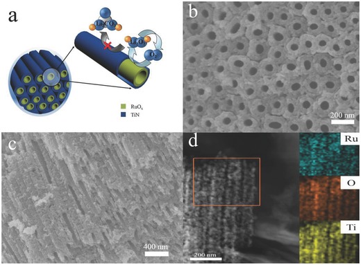
a) Schematic illustration of interface reaction on RuOx (yellow layer)/TiN NTA (blue layer) electrode. b) Top‐view SEM image of RuOx/TiN NTA. c) Cross‐sectional SEM image of RuOx/TiN NTA. d) Typical STEM image of RuOx/TiN NTA.
2. Results and Discussion
As schematically shown in Figure 1a, we synthesize RuOx/TiN NTA through the process including anodization, calcination in ammonia, and electrodeposition. After anodization and nitrization, TiN NTA was obtained.33 Through optimizing the condition of electrodeposition, ruthenium oxide was uniformly deposited into this structure to form coaxial nanotube arrays. Scanning electron microscopy (SEM) images of the obtained RuOx/TiN NTA clearly display the coaxial nanotube arrays morphology with outer diameters in the range of 120–150 nm (Figure 1b,c), and the thickness of RuOx layer is about 10–15 nm. Furthermore, elemental mapping also reveals a uniform distribution of Ru and O in the TiN NTA (inset of Figure 1d). This unique binder‐free nanostructure with firm contact of Ti mesh substrate may facilitate electronic conductivity, as well as the diffusion of reactant gases. Furthermore, the even coverage of Ru species on TiN support without binder is highly desirable for promoting the oxygen reduction reaction (ORR) and the oxygen evolution reaction (OER).
To demonstrate the main components in the as prepared samples, X‐ray photoelectron spectroscopy (XPS) analysis of RuOx 30, 34, 35, 36, 37 is illustrated in Figure 2 (the demonstration of TiN NTA has been provided in our previous studies). Herein, only the peak of below 283 eV is analyzed as shown in Figure 2a, because C 1s peak at 284.8 eV influences on the judgment of Ru peaks. The binding energy of Ru 3d5/2 peak at 280.9 eV is attributed to RuO2.34 The Ru 3d5/2 peak at 280.3 eV peak is generally in line with the values of Ru,35 which may be a small amount of adsorbed elemental Ru from the electrolyte. Another peak of Ru 3d5/2 spectrum at 282.2 eV is assigned to Ru of oxidation state higher than IV+,36, 37 which is probably caused by the excessive oxidation on surface. The O 1s spectrum (Figure 2b) shows two oxygen contributions at 530.1 and 532.2 eV.35 It illustrates the main existence of ruthenium oxide, especially RuO2.
Figure 2.
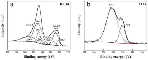
a) Ru 3d XPS spectrum of RuOx/TiN NTA. b) O 1s XPS spectrum of RuOx/TiN NTA.
As a carbon‐ and binder‐free cathode, TiN NTA electrode exhibited decent electrochemical performance, showing discharge and charge potential of 2.7 and 4.0 V, respectively, with a capacity of 500 mAh g−1 (Figure 3 ). By contrast, TiN nanoparticles reveal a very high overpotential with the cut‐off capacity of 500 mAh g−1, which is consistent with Bruce's result (Figure S1, Supporting Information). This significantly improved round‐trip efficiency of TiN NTA can be ascribed to the enhanced electronic conductivity of this unique binder‐free nanostructrure. Compared with previous reports of promising noncarbon substrates, this self‐standing TiN NTA also delivered satisfactory capacity and energy efficiency.19, 20
Figure 3.
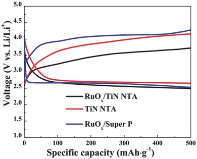
Li–O2 cell discharge/charge profiles of TiN NTA, RuOx/TiN NTA, and RuOx/super P‐based electrodes in TEGDME electrolyte containing 1 m LiTFSI with a cut‐off capacity of 500 mAh g−1 at the current density of 50 mA g−1 for the first cycle.
Subsequently, ruthenium oxide was chosen, because it was generally viewed as an efficient catalyst. As shown in Figure 3, the cell containing RuOx/TiN NTA electrode demonstrated a notable lower charge voltage than that of TiN NTA, while the discharge voltage of the cell with RuOx/TiN NTA electrode is similar to that of the cell with TiN NTA electrode. According to the XPS and differential electrochemical mass spectrometry (DEMS) analyses discussed later (Figures 4 and 6), the dominate reaction at RuOx/TiN NTA electrode is the reversible formation/decomposition of Li2O2. These results suggest that RuOx could effectively promote the OER, thus reducing the overpotential of the discharge–charge process. As a fair comparison, the profiles of the RuOx/Super P electrode as cathodes are tested under the same current density (Figure 3). The charging voltage of Li–O2 batteries with the RuOx/TiN NTA electrode is clear lower than that of RuOx/Super P electrode. The result illustrates that binder‐free TiN NTA substrate can be a promising replacement of carbon material for Li–O2 battery cathodes.
Figure 4.
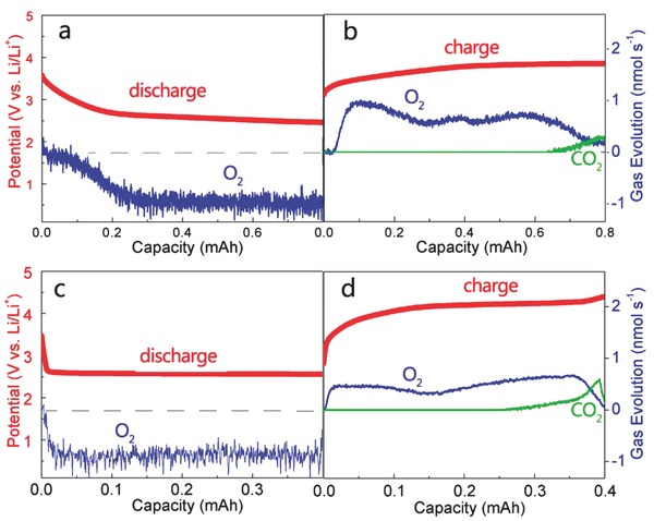
Differential electrochemical mass spectrometry (DEMS) analysis of the evolved gases during the a) discharge and b) charge of a Li–O2 cell with RuOx/TiN NTA cathode. DEMS analysis of the evolved gases during the c) discharge and d) charge of a Li–O2 cell with Super P cathode. The right axis represents the detected gas evolution of O2 (blue line) and CO2 (green line), the left axis shows the potential of the discharging step and charging step (red line).
Figure 6.

Product detection. a) Li 1s peaks of RuOx/TiN NTA cathode at different stages by XPS. b) O 1s peaks of RuOx/TiN NTA cathode at different stages by XPS. The green lines, the purple lines, and the blue lines belong to Li2O2, Li2CO3, and RuOx, respectively.
To confirm the discharge process was overwhelmingly dominated by Li2O2 formation, we used DEMS to monitor the ORR and OER process. Under the flow of O2/Ar (20% O2) during discharging, O2 was consumed below the potential of 2.9 V, suggesting the formation of Li2O2. There was no ionic current of CO2 and H2 detected from the mass spectrometry during discharging (Figure 4a). To demonstrate the reversible decomposition of Li2O2, the evolved gas species during charging process were also analyzed. Parallel to the beginning of the charging step, the acceleration of O2 evolution was observed below 3.5 V. In contrast to ORR process with a steady rate of O2 consumption, slight peaks were shown in the profile of O2 evolution. According to previous reports, the variation of O2 evolution rate may indicate the different reaction processes of Li2O2 decomposition during charging process.38 The cell voltage was maintained under 4 V until the notable decrease of O2 evolution take place. At the end of charging process, only trace amount of CO2 was detected (Figure 4b), indicating the carbonates formation was insignificant. Because the RuOx/TiN NTA is carbon‐free, it is logical to ascribe the carbonates to the slight decomposition of electrolyte. As a fair comparison, the cell of Super P electrode was investigated with the same current density (Figure 4c,d). Even with the cut‐off capacity of 0.4 mAh, the charging potential quickly ascended to 4.2 V. Furthermore, steep profile of CO2 formation was observed along with the O2 evolution process, suggesting the significant degradation of electrolyte and carbon materials and subsequent oxidation of these species to CO2. It should be noted that the RuOx/TiN NTA facilitated a separation of main OER from the CO2 evolution process, while in Super P cell both of the gas evolution processes occurred simultaneously during high charging potential. Moreover, the e−/O2 value data for discharge and charge were displayed in Table S1,Supporting Information. This result suggested that the side reaction evolving CO2 could be effectively limited under a proper cut‐off voltage in RuOx/TiN NTA‐based cell, without hindering the complete decomposition of Li2O2.
Stable cyclability is one of the most critical aspects of Li–O2 battery. As shown in Figure 5 a, the cell with the RuOx/TiN NTA electrode showed good cycling capability over ten cycles with a cut‐off capacity of 500 mAh g−1 at the current density of 50 mA g−1. The charge voltage of Li–O2 battery with the RuOx/TiN NTA cathode stabilizes below 3.8 V on the subsequent ten cycles, and the discharge voltage stays at about 2.5 V after the tenth cycling. Furthermore, the cycling ability of RuOx/Super P‐based Li–O2 cell was tested for comparison in the same conditions, which showed poor cyclability (Figure S2, Supporting Information). This superior cycling ability of RuOx/TiN NTA‐based Li–O2 cell may be attributed to the interface stability of carbon‐ and binder‐free electrode, avoiding the side reaction of carbon materials to generate Li2CO3 during the charging process. As shown in Figure 5b, the charge terminal voltages for the 300 cycles were quite stable, as the RuOx/TiN NTA‐based Li–O2 cell cycled over 2000 h with a cut‐off capacity of 500 mAh g−1 at the current density of 150 mA g−1. Besides, RuOx/TiN NTA‐based Li–O2 batteries exhibited acceptable rate performance. The charge voltages were below 4.0 V with a cut‐off capacity of 500 mAh g−1 at the current density of 20, 50, 100, and 150 mA g−1, respectively (Figure 5c). All the above‐mentioned results indicate the promising OER catalytic activity, good electronic conductivity, and enhanced interface stability of the RuOx/TiN NTA cathode, which is quite desirable for high performance Li–O2 batteries to alleviate the overpotential and improve the cycling ability.
Figure 5.
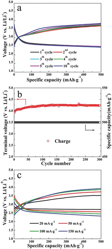
a) Discharge and charge voltage profiles of the RuOx/TiN NTA‐based cell at various cycles with a cut‐off capacity of 500 mAh g−1 at the current density of 50 mA g−1. b) The charge terminal voltage of the RuOx/TiN NTA‐based cell after 300 cycles with a cut‐off capacity of 500 mAh g−1 at the current density of 150 mA g−1. c) Discharge and charge voltage profiles of the RuOx/TiN NTA‐based cell at various cycles with a cut‐off capacity of 500 mAh g−1 at the varied current density of 20, 50, 100, and 150 mA g−1.
In order to detect the discharge product of the RuOx/TiN NTA cathode after cycling, XPS analysis was conducted. Figure 6 presents the Li 1s and O 1s spectra of the discharged and charged RuOx/TiN NTA cathode, respectively. Li2O2 can be assigned as the major discharge product from the Li 1s signal with a binding energy of 54.5 eV in Figure 6a and most of the Li species are decomposed in the following charging process. The O 1s peak at 531.1 eV is generally in line with the values of Li2O2 in Figure 6b. And a weak peak at 532.9 eV is attributed to Li2CO3, which may be caused by the decomposition of the electrolyte or short time exposure to ambient air of sample before testing.18 After charging process the peaks of Li2O2 disappear, and the peaks of O 1s return to the status of pristine cathode. This result is also consistent with the DEMS data shown in Figure 4b. With tenth cycling, the formation/decomposition of Li2O2 can still be observed through the Li 1s and O 1s spectra, while a slight increasing amount of Li2CO3 was also detected after the tenth discharge process. However, Raman spectroscopy gave no clear evidence of Li2CO3 formed during the discharge and charge process (Figure S3, Supporting Information). These XPS and Raman results discussed above illustrate Li2O2 as dominate discharge product during cycling. This carbon‐ and binder‐free electrode is beneficial to avoid the reaction of carbon materials with intermediates to generate Li2CO3 during charging process, thus reducing the overpotential of the discharge–charge process and improving the cycling ability.
3. Conclusion
In summary, we adopted electrodeposition to construct a self‐standing coaxial RuOx/TiN NTA electrode for nonaqueous Li–O2 batteries. TiN NTA support is the key to this carbon‐ and binder‐free electrode, providing ideal distribution of catalyst and fast electron transport. Compared with Super P based cathode, this self‐standing electrode exhibits significantly improved electrochemical performance with lower overpotential and enhanced cyclability, as this carbon‐free electrode can avoid the side reaction caused by carbon material oxidation during the charging process. Our study suggests that TiN materials can serve as a candidate for carbon‐free electrode with the utilization of appropriate nanostructure. Moreover, these results further imply the critical role of cathode structure designing for improving Li–O2 battery performance.
4. Experimental Section
Preparation of TiN NTA: First, TiO2 nanotube arrays were prepared by the anodization of a 5 × 5 × 0.23 mm Ti mesh substrate (>99.6%, GoodFellow) in a two‐electrode cell containing a Pt counter electrode. The anodization was performed at 60 V in a solution of 0.1 wt% NH4F in ethylene glycol (99.8% anhydrous, Sigma‐Aldrich) at room temperature for 5 h. The as‐prepared TiO2 nanotube arrays were cleaned with ethyl alcohol, and then calcined in a tubular furnace at 800 °C under ammonia for 3 h. After cooling to room temperature, TiN nanotube arrays were finally obtained.
Preparation of RuOx/TiN NTA Electrode: Electrodeposition was done by using a CHI440A electrochemical workstation (CHI Instrument Inc.) at room temperature with a three electrode cell consisting of a saturated calomel electrode (SCE) as the reference electrode, a 10 × 10 mm platinum plate as the counter electrode, and TiN NTA as the working electrode. The electrolyte is 5 × 10⁻³ m RuCl3 • xH2O aqueous solution and add HCl to adjust pH value to be 2. Then, to obtain coaxial RuOx/TiN NTA, RuOx was deposited on TiN NTA using cyclic voltammetry performed in the electrolyte with the potential range between −0.8 and 1.5 V, with a scan rate of 20 mV s−1. After deposition, the sample was washed several times with deionized water carefully. Then the sample was put into a vacuum oven at 120 °C for 8 h. The RuOx/TiN NTA electrode were prepared.
Characterization: The morphology of the RuOx/TiN NTA was attained from SEM, HITACHI S‐4800. Scanning transmission electron microscope (STEM) and energy dispersive X‐ray spectroscopy (EDX) elemental mapping were obtained from Tecnai F20. XPS was carried out by an ESCALab220i‐XL electron spectrometer using Al Ka radiation. Data were fitted by CasaXPS after correction by setting the internal reference C1s peak to 248.8 eV. DEMS was based on a commercial magnetic sector mass spectrometer (Thermo Fischer) with turbomolecular pump (Pfeiffer Vacuum) that is backed by a dry scroll pump (Edwards) and leak inlet which samples from the purge gas stream. The cell with RuOx/TiN NTA cathode discharges under the flow (5 mL min−1) of O2/Ar (20% O2) and charges under the flow (5 mL min−1) of Ar with a cut‐off capacity of 0.8 mAh at the current density of 70 mA g−1. And the cell with Super P cathode also discharges and charges with a cut‐off capacity of 0.4 mAh under the same condition. Raman spectra were acquired in a customized air‐tight sample holder using a micro‐Raman system (DXRxi, Thermo Scientific) with a 532 nm laser excitation. Then the cathode was assembled into a custom‐made air‐tight sample holder with a thin quartz window. All samples about discharge product were washed three times by dimethoxyethane (DME, Signal‐Aldrich) in the glove box and reduced their exposure to air as much as possible before testing.
Li–O2 Cell Assembly and Tests: Electrochemical experiments were carried out by using a swagelok cell with a hole drilled only on the cathode of the current collector to enable oxygen flow in. Lithium metal disks (8 mm diameter) were used as the anode. A glass fiber and polypropylene (Celgard 2400) were used as separators to separate the anode and cathode. The organic electrolyte consists of a solution of 1 m bis(trifluoromethane)sulfonamide lithium salt (LiTFSI, Sigma‐Aldrich) in tetraethylene glycol dimethyl ether (TEGDME, Sigma‐Aldrich). RuOx‐decorated TiN NTAs on Ti mesh (0.25 cm2) were used as the cathode directly without further treatment. The mass of RuOx/TiN NTA on Ti mesh substrate was 0.44 mg cm−2 approximately. The mass of TiN NTA was about 0.41 mg cm−2, which is calculated according to our previous report.21 And the mass of deposited RuOx was determined by a microbalance with 0.03 mg cm−2 after 50 laps electrodeposition, which is in agreement with referenced Yim's report.31 Therefore, the mass ratio of RuOx/TiN NTA is 0.07 approximately.
For comparison, the RuOx/Super P electrodes (typically 0.5 mg) were prepared by mixing 90 wt% Super P and 10 wt% PTFE binders. The samples were rolled into slices and cut into square pieces of 0.5 × 0.5 cm and then pasted on a stainless steel current collector under a pressure of 5 MPa. Finally, RuOx was electrodeposited into the surface of current collector by the same method with RuOx/TiN NTA electrode.
The Li–O2 cells were assembled inside of the glove box under an argon atmosphere (<1 ppm H2O and O2). Galvanostatical discharge−charge experiments were carried out with a LAND battery testing system. All electrochemical measurements were carried out at room temperature.
Supporting information
As a service to our authors and readers, this journal provides supporting information supplied by the authors. Such materials are peer reviewed and may be re‐organized for online delivery, but are not copy‐edited or typeset. Technical support issues arising from supporting information (other than missing files) should be addressed to the authors.
Supplementary
Acknowledgements
Y.C. and S.D. contributed equally to this work. This work was supported by the Key Research Program of the Chinese Academy of Sciences (Grant No. KGZD‐EW‐202‐2), National Natural Science Foundation of China (Grant Nos. 21271180, 21301185, and 21473228), Science and Technology Program on Basic Research Project of Qingdao (13‐1‐4‐174‐jch), and the Key Technology Research Projects of Qingdao (No. 13‐4‐1‐10‐gx).
Chang Y., Dong S., Ju Y., Xiao D., Zhou X., Zhang L., Chen X., Shang C., Gu L., Peng Z., Cui G. (2015). A Carbon‐ and Binder‐Free Nanostructured Cathode for High‐Performance Nonaqueous Li‐O2 Battery. Adv. Sci., 2: 1500092. doi: 10.1002/advs.201500092
References
- 1. Girishkumar G., McCloskey B., Luntz A. C., Swanson S., Wilcke W., J. Phys. Chem. Lett. 2010, 1, 2193. [Google Scholar]
- 2. Choi N. S., Chen Z., Freunberger S. A., Ji X., Sun Y. K., Amine K., Yushin G., Nazar L. F., Cho J., Bruce P. G., Angew. Chem. Int. Ed. 2012, 51, 9994. [DOI] [PubMed] [Google Scholar]
- 3. Black R., Adams B., Nazar L. F., Adv. Energy. Mater. 2012, 2, 801. [Google Scholar]
- 4. McCloskey B. D., Scheffler R., Speidel A., Bethune D. S., Shelby R. M., Luntz A. C., J. Am. Chem. Soc. 2011, 133, 18038. [DOI] [PubMed] [Google Scholar]
- 5. Gallant B. M., Mitchell R. R., Kwabi D. G., Zhou J., Zuin L., Thompson C. V., Yang S., J. Phys. Chem. C 2012, 116, 20800. [Google Scholar]
- 6. Chen Y., Freunberger S. A., Peng Z., Fontaine O., Bruce P. G., Nat. Chem. 2013, 5, 489. [DOI] [PubMed] [Google Scholar]
- 7. Peng Z., Freunberger S. A., Chen Y., Bruce P. G., Science 2012, 337, 563. [DOI] [PubMed] [Google Scholar]
- 8. Sun B., Huang X., Chen S., Munroe P., Wang G., Nano Lett. 2014, 14, 3145. [DOI] [PubMed] [Google Scholar]
- 9. Kitaura H., Zhou H., Adv. Energy Mater. 2012, 2, 889. [Google Scholar]
- 10. Li J., Wang N., Zhao Y., Ding Y., Guan L., Electrochem. Commun. 2011, 13, 698. [Google Scholar]
- 11. Ottakam Thotiyl M. M., Freunberger S. A., Peng Z., Bruce P. G., J. Am. Chem. Soc. 2013, 135, 494. [DOI] [PubMed] [Google Scholar]
- 12. Li F., Tang D., Chen Y., Golberg D., Kitaura H., Zhang T., Yamada A., Zhou H., Nano Lett. 2013, 13, 4702. [DOI] [PubMed] [Google Scholar]
- 13. Riaz A., Jung K. N., Chang W., Shin K. H., Lee J. W., ACS Appl. Mater. Interfaces 2014, 6, 17815. [DOI] [PubMed] [Google Scholar]
- 14. Kim S. T., Choi S. N., Park S., Cho J., Adv. Energy Mater. 2014, 1. [Google Scholar]
- 15. Thotiyl M. M. O., Freunberger S. A., Peng Z., Chen Y., Liu Z., Bruce P. G., Nat. Mater. 2013, 12, 1050. [DOI] [PubMed] [Google Scholar]
- 16. Dong S., Chen X., Gu L., Zhou X., Xu H., Wang H., Liu Z., Han P., Yao J., Wang L., Cui G., Chen L., ACS Appl. Mater. Interfaces 2011, 3, 93. [DOI] [PubMed] [Google Scholar]
- 17. Wen Z., Cui S., Pu H., Mao S., Yu K., Feng X., J. Chem. Adv. Mater. 2011, 23, 5445. [DOI] [PubMed] [Google Scholar]
- 18. Xie J., Yao X., Madden I. P., Jing D., Chou L., Taung C., Wang D., J. Am. Chem. Soc. 2014, 136, 8903. [DOI] [PubMed] [Google Scholar]
- 19. Adams B. D., Black R., Radtke C., Williams Z., Mehdi B. L., Browning N. D., Nazar L. F., ACS Nano 2014, 8, 12483. [DOI] [PubMed] [Google Scholar]
- 20. Li F., Ohnishi R., Yamada Y., Kubota J., Domen K., Yamada A., Zhou H., Chem. Commun. 2013, 49, 1175. [DOI] [PubMed] [Google Scholar]
- 21. Dong S., Chen X., Gu L., Zhou X., Li L., Liu Z., Han P., Xu H., Yao J., Wang H., Zhang X., Shang C., Cui G., Chen L., Energy Environ. Sci. 2011, 4, 3502. [Google Scholar]
- 22. Dong S., Chen X., Wang S., Gu L., Zhang L., Wang X., Zhou X., Liu Z., Han P., Duan Y., Xu H., Yao J., Zhang C., Zhang K., Cui G., Chen L., ChemSusChem 2012, 5, 1712. [DOI] [PubMed] [Google Scholar]
- 23. Nasybulin E., Xu W., Engelhard M. H., Nie Z., Li X. S., Zhang J. G., J. Power Sources 2013, 243, 899. [Google Scholar]
- 24. Black R., Oh S. H., Lee J. H., Yim T., Adams B., Nazar L. F., J. Am. Chem. Soc. 2012, 134, 2902. [DOI] [PubMed] [Google Scholar]
- 25. Wang Z., Xu D., Xu J., Zhang X., Chem. Soc. Rev. 2014, 43, 7746. [DOI] [PubMed] [Google Scholar]
- 26. Zhang T., Zhou H., Angew. Chem. Int. Ed. 2012, 51, 1. [DOI] [PubMed] [Google Scholar]
- 27. Li F., Murali S., Tang D., Jianh Z., Liu D., Golberg D., Yamada A., Zhou H., Adv. Mater. 2014, 26, 4659. [DOI] [PubMed] [Google Scholar]
- 28. Jian Z., Liu P., Li F., He P., Guo X., Chen M., Zhou H., Angew. Chem. Int. Ed. 2013, 52, 1. [Google Scholar]
- 29. Li F., Chen Y., Tang D., Jian Z., Liu C., Golberg D., Yamada A., Zhou H., Energy Environ. Sci. 2014, 7, 1648. [Google Scholar]
- 30. Susanti D., Tsai D., Huang Y., Korotcov A., Chung W., J. Phys. Chem. 2007, 111, 9530. [Google Scholar]
- 31. Ryu I., Yang M., Kwon H., Park H. K., Do Y. R., Lee S. B., Yim S., Langmuir, 2014, 30, 1704. [DOI] [PubMed] [Google Scholar]
- 32. Yang Y., Liu W., Wang Y., Wang X., Xiao L., Lu J., Zhang L., Phys. Chem. Chem. Phys. 2014, 16, 20618. [DOI] [PubMed] [Google Scholar]
- 33. Jiang W., Li G., Gao X., Chem. Commun. 2009, 44, 6720. [DOI] [PubMed] [Google Scholar]
- 34. Wang G., Hsieh C. S., Tsai D. S., Chen R. S., Huang Y. S., J. Mater. Chem. 2004, 14, 3503. [Google Scholar]
- 35. Foelske A., Barbieri O., Hahn M., Kotz R., Electrochem. Solid State Lett. 2006, 9, A268. [Google Scholar]
- 36. Reuter K., Scheffler M., Surf. Sci. 2001, 490, 20. [Google Scholar]
- 37. Over H., Seitsonen A. P., Lundgren E., Smedh M., Andersen J. N., Surf. Sci. 2002, 504, L196. [Google Scholar]
- 38. Lu Y., Yang S., J. Phys. Chem. Lett. 2013, 4, 93. [DOI] [PubMed] [Google Scholar]
Associated Data
This section collects any data citations, data availability statements, or supplementary materials included in this article.
Supplementary Materials
As a service to our authors and readers, this journal provides supporting information supplied by the authors. Such materials are peer reviewed and may be re‐organized for online delivery, but are not copy‐edited or typeset. Technical support issues arising from supporting information (other than missing files) should be addressed to the authors.
Supplementary


