Abstract
Susceptibility weighted imaging (SWI) is a method that uses the intrinsic nature of local magnetic fields to enhance image contrast in order to improve the visibility of various susceptibility sources and to facilitate the diagnostic interpretation. It is also the precursor to the concept of using phase for quantitative susceptibility mapping (QSM). Nowadays, SWI has become a widely used clinical tool to image deoxyhemoglobin in veins, iron deposition in the brain, hemorrhages, microbleeds, and calcification. In this paper, we review the basics of SWI, including data acquisition, data reconstruction and post-processing. In particular, the source of cusp artifacts in phase images is investigated in detail and an improved multi-channel phase data combination algorithm is provided. In addition, we show a few clinical applications of SWI for imaging stroke, traumatic brain injury, carotid vessel wall, siderotic nodules in cirrhotic liver, prostate cancer, prostatic calcification, spinal cord injury and intervertebral disc degeneration. As the clinical applications of SWI continue to expand both in and outside the brain, improving SWI in conjunction with QSM is an important future direction of this technology.
Keywords: susceptibility weighted imaging, quantitative susceptibility mapping, phase imaging, multi-channel phase data combination, stroke, cerebral microbleeds
1. Introduction
Susceptibility weighted imaging (SWI) is a method that uses the intrinsic nature of local magnetic fields to enhance image contrast to improve the visibility of various susceptibility sources and to facilitate the diagnostic interpretation (1–8). Historically, the idea for SWI came from the fact that bulk susceptibilities change the local frequency, similar to what happens with chemical shift in spectroscopy, but in this case as a function of the geometry of the object (1–8). It is also a precursor to the concept of using phase for quantitative susceptibility mapping (QSM) (8–11). Imaging deoxyhemoglobin lies at the root of imaging veins. SWI provided a means to enhance the contrast between veins and surrounding tissue, especially as the level of deoxyhemoglobin changes in diseases such as stroke. Unlike spectroscopic imaging of metabolites where the water signal needs to be suppressed, the macro-effects of local susceptibility are immediately apparent. Further, the signatures of spheres and cylinders are unique and the polarity of each as seen in the phase images can be used to distinguish calcium from iron (which is not the case in magnitude images) (12). The only thing that had basically prevented phase from being used earlier was the fact that there were macroscopic fields permeating the image masking out the interesting structural information. The early papers on SWI dealt with this by performing a homodyne high-pass filter that basically removed all the low spatial frequencies leaving visible the now well-known local susceptibility effects of veins, microbleeds, calcium and iron deposition in structures like the basal ganglia and midbrain (3–8). Now this phase information can be used by itself (1), or to generate a new mask to enhance the contrast in the magnitude image, creating what was called the SWI data or susceptibility weighted image (8). This form is currently available on several manufacturers’ systems and it has spurred the writing of papers that cite SWI more than 1000 times in the literature, most of which are clinical in nature. The predominant use of SWI is imaging venous oxygen saturation (2–4,13,14), iron deposition (15–17) and calcification (18,19) in the brain, but there are a few studies venturing to other parts of the body such as those studying the vessel wall in the leg (20), bleeding in the spine (21) and some abdominal applications looking for either bleeding or increased iron content (22–24). The main focus in the past has been on subtle changes in susceptibility in the brain, but recently it has become clear that the past sources of angst in phase imaging, the air/tissue, bone and calcium deposits may actually be important sources of information in and of themselves (25). With the susceptibility maps in hand, one can make the next big leap to improve SWI and that is using the susceptibility maps themselves to create masks allowing for true susceptibility weighted imaging (tSWI) where phase dependence on angle and shape is no longer a concern (26,27). This may open the door to the use of susceptibility mapping methods at not just long echoes but also at short echoes, since these susceptibility effects are large enough to be easily seen there.
Although SWI is a technically straight-forward process, care should be taken to reduce unwanted and confounding artifacts which arise from sources such as air/bone-tissue interface (28) and uncompensated blood flow (29). In this paper, we will review the details in data acquisition and post-processing of SWI, and introduce strategies which may further improve its quality and accuracy. Specifically, we will discuss: 1) theories and data processing steps in SWI (homodyne high-pass filtering, susceptibility weighting mask, orientation dependence and tSWI); 2) data acquisition for SWI (echo time, resolution, simultaneous MRA/SWI); 3) data reconstruction (multi-channel phase data combination and cusp artifacts); and 4) clinical applications of SWI (imaging stroke, cerebral microbleeds, carotid vessel wall, siderotic nodules in cirrhotic liver, prostate cancer and prostatic calcification, spinal cord injury, as well as intervertebral disc degeneration). With these things in mind, we now proceed to discuss the basics of SWI followed by current and future applications.
2. Basics of SWI
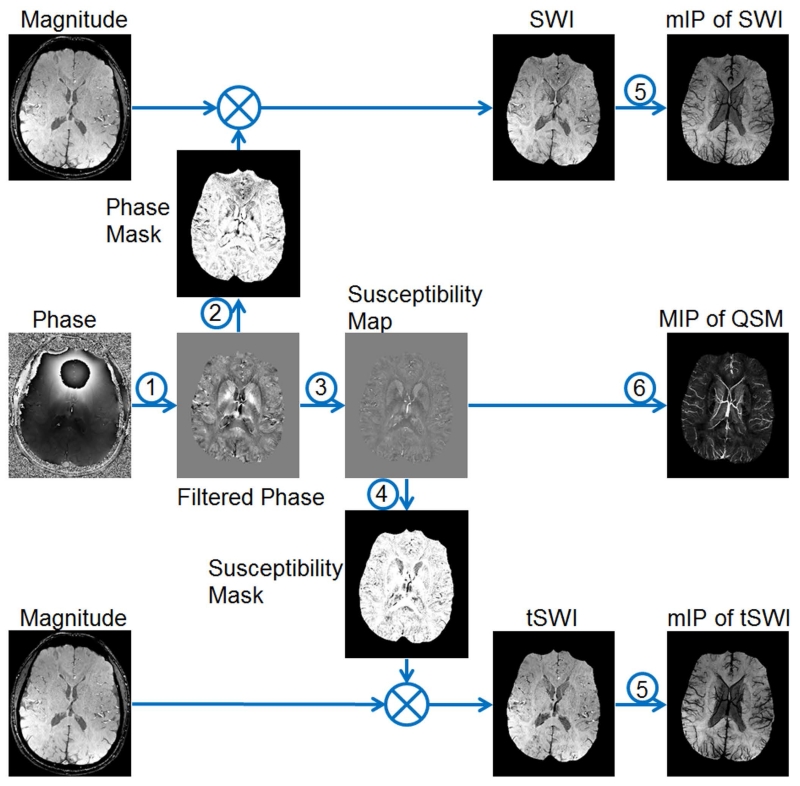
In SWI, the phase images are used to create weighting masks which will be multiplied to the magnitude images to enhance the susceptibility contrast (8,30). An overview of the data processing steps is given in Figure 1. In this section, detailed discussions on background phase removal and susceptibility weighting mask generation are provided.
Figure 1.
Overview of data processing steps in SWI. 1: background phase removal. 2: generating the weighting masks using filtered phase images for conventional SWI. 3: quantitative susceptibility mapping (QSM). 4: generating the weighting masks using susceptibility maps for tSWI. 5: minimum intensity projection (mIP). 6. maximum intensity projection (MIP).
2.1. Background phase removal
For a left-handed system, the phase of the signal acquired using a gradient-echo sequence is given as
| [1], |
where ΔB(r) is the field variation, γ the gyromagnetic ratio, TE the echo time and ϕ0(r) the TE-independent phase offset which is mainly related to coil-sensitivity and tissue conductivity (12,31,32). ΔB(r) contains both the components induced by the global sources such as air-tissue interface and local sources such as the susceptibility distribution of brain tissues (12). Various algorithms have been proposed to remove the former component (33–36). This background field removal step is critical to both SWI and QSM (9). In SWI, the background field is traditionally removed through the homodyne high-pass filtering (8). The sophistication of this algorithm is attributed to its simplicity in implementation and effectiveness in reducing the background field which has relatively lower spatial frequency than the local field variation. A particular advantage of homodyne high-pass filtering is that no phase unwrapping is required, since homodyne high-pass filtering is applied to the complex data directly as
| [2], |
where FT and FT−1 represent the forward and inverse Fourier transform, while / and ∙ represent point-wise division and multiplication. H(k) is conventionally chosen to be the Hanning window (8,30). The size of the Hanning window applied in k-space is usually used to indicate the effects of high-pass filtering, with larger window size leads to more suppression of the low spatial frequencies (9). Typically, the window size is 64×64 for a 512×512 matrix (8). The homodyne high-pass filtering is commonly applied in 2D, i.e., in a slice-by-slice fashion. This makes it suitable for processing the data collected with not only a 3D sequence but also a 2D sequence which may cause shifts in the baseline of the phase in different slices. In addition, operating in 2D gives more flexibility in implementing the algorithm in a more time and memory efficient way. For example, one can choose to apply homodyne high-pass filtering in parallel to each slice acquired from each coil prior to the multi-channel data combination, without processing the whole 3D volumes which may require a memory size too big to be practical. This channel-by-channel high-pass filtering turns out to be advantageous for SWI in eliminating the phase singularities, known as cusp artifacts, as will be discussed in Section 4.
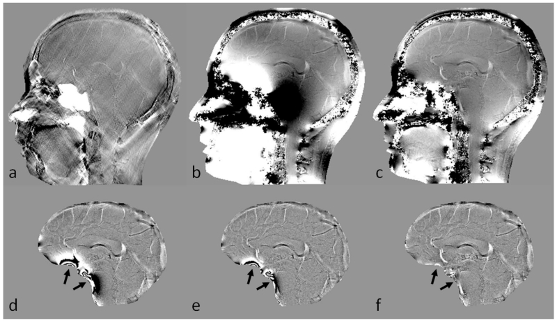
However, homodyne high-pass filtering may lead to a loss of phase information induced by the local susceptibility distribution (28,33,34). This will in turn lead to under-estimation of the susceptibilities in quantitative susceptibility mapping (9). One way to reduce this signal loss is to predict the field variation induced by the air-tissue interface, using a priori information about the geometries, and then remove this predicted field before applying homodyne high-pass filtering (25,28). This enables the use of a much smaller filter size and thus preserves the local phase information better, as demonstrated in Figure 2. In fact, a much milder filter can be used in the central part of the brain where the global geometry induced phase has lower spatial frequency, while a stronger filter can be used in regions close to the air-tissue interface (9). This is better than conventional homodyne high-pass filtering since more local phase information can be preserved, especially for basal ganglia structures which are usually the structures of interest for studies focused on in vivo iron deposition. For structures near the edge of the brain (e.g., the cerebral cortex), the accuracy in preserving the local phase will be much lower than in the central part. This is a common problem even for some newer algorithms (33–36). Most recently developed background phase removal algorithms are based on the spherical mean value property of harmonic functions to separate the background phase (harmonic) and the local phase (non-harmonic) (33,35,36). These algorithms have been demonstrated to be effective in preserving the local phase, much better than the conventional high-pass filtering. This is largely attributed to the deconvolution step in the end, in which the effects of spherical mean value filtering on the local phase are compensated by solving an inverse problem (33,35,36). Clearly, the accuracies of these algorithms will also be dependent on the deconvolution which requires regularization. In other background phase removal algorithms, the susceptibility distribution of the air/bone-tissue interface is estimated, in order to predict the induced field (25,34). This procedure can be performed either prior to or simultaneously with the mapping of susceptibilities of the structures inside the brain (34,37). Except for homodyne high-pass filtering, phase unwrapping is required for background phase removal (33–37). Consequently, homodyne high-pass filtering is still the most popular phase processing algorithm for SWI.
Figure 2.
Background phase removal using forward modeling. a. Susceptibility map b. Unwrapped phase image at TE = 7.5ms. c. Resultant phase after subtracting the predicted phase induced by sinuses and bones. d. Homodyne high-pass pass filtering (k-space window size = 32×32) result of b. e. Homodyne high-pass filtering (k-space window size = 64×64) result of b. f. Homodyne high-pass filtering (k-space window size = 32×32) result of c. There are still remnant background phase artifacts even after applying a 64×64 high-pass filter to the original phase image (e). Removal of the predicted phase due to sinuses and bones helped in suppressing most of this unwanted background phase, together with a milder high-pass filter (arrows in d, e and f).
2.2. Susceptibility weighting masks, orientation dependence and true-SWI
Susceptibility weighting masks are generated from the high-pass filtered phase images. Usually only the positive (negative) phase for a left- (right-) handed system will be used to enhance the contrast between iron content/veins and surrounding tissues, for images acquired in a transverse view, while the phase with the opposite sign will have a weighting factor of one:
| [3]. |
In the above equation, it is assumed that |ϕ(r)| ≤ π, which is true when homodyne high-pass filtering is used. For the local phase obtained using other algorithms, W(r) is set to 0 when ϕ(r) > π.
This strategy, designed to enhance the paramagnetic content, is very effective for visualizing the veins, microbleeds etc., as has been proved in various clinical applications. One can also choose to enhance the diamagnetic content by reversing the sign of phase first and then create the weighting masks using the same procedures. However, the remnant background phase may also cause false enhancement, especially in regions close to the sinuses, which will lead to dark regions with reduced contrast on the SWI data. This can be solved by using more advanced background phase removal techniques (28,33,34,38) or using a stronger high-pass filter (39). Alternatively, regions affected by remnant background phase can be avoided in creating the susceptibility weighting masks. For example, a Fermi weighting function using the local field gradients was created to suppress the effects of remnant background phase on the weighting masks (40).
Finally, susceptibility weighted images are generated by multiplying the weighting masks into the original magnitude images:
| [4], |
where the number of multiplications, n, is usually chosen to be 4 to maximize the CNR (8). For better visualization, a minimum intensity projection is commonly used in the end.
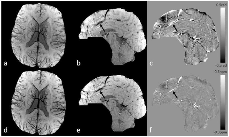
However, due to the orientation-dependence nature of phase information, there are also limitations in SWI related to faithfully delineating the actual geometries, especially for veins aligned at the magic angles in a high imaging resolution setting (26), as shown in Figure 3. This leads to the idea of using the susceptibility maps, instead of the phase images, to create susceptibility weighting masks (26,27). We named this method true susceptibility weighted imaging (tSWI), as the weighting is now directly associated with the susceptibility distribution, which is not dependent on orientation and imaging parameters (to a large extent). For example, tSWI has been shown to improve the delineation of the veins and microbleeds in TBI (9,26). Nonetheless, conventional SWI might be better in detecting small objects such as subvoxel microbleeds, for which the susceptibility quantification is subject to large uncertainty while the phase still clearly indicates the presence of those small objects (9).
Figure 3.
Conventional SWI vs. true SWI (tSWI). a. Minimum intensity projection (mIP) of conventional SWI. b. Single slice conventional SWI in sagittal view. c. High-pass filtered phase image. d. mIP of tSWI. e. Single slice tSWI in sagittal view. f. Susceptibility map generated from c using the geometry constrained iterative SWIM algorithm (65). The quality of conventional SWI is similar to that in tSWI for visualizing the veins in transverse view (a and d). The orientation dependent phase causes improper enhancement of the vein in sagittal view on conventional SWI (arrows in b and c). This orientation dependence is avoided in tSWI (arrows in e and f). Images in sagittal view (b, c, e, and f) are all at the same anatomical position, and were interpolated to isotropic resolution for better visualization.
3. Data acquisition
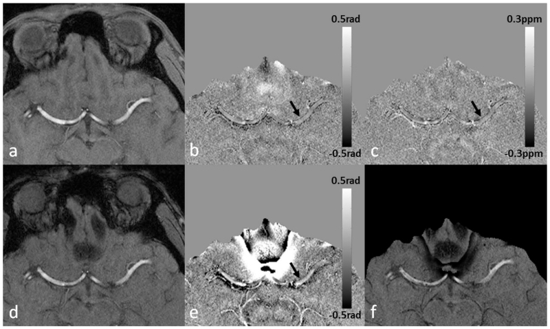
Data are conventionally acquired using gradient-echo sequences. The example imaging parameters for different SWI applications are listed in Table 1 (modified from the appendix in ref. (9)). For visualization of the veins, 3D full flow compensation (including compensation in slab select, phase and partition encoding, as well as readout directions) is preferred to avoid flow artifacts (although phase encoding and partition encoding flow compensation can be avoided but then there will be shift artifacts in fast flowing angled vessels) (12,41,29). The presence of background field gradients may cause failure in flow compensation, even with the ideal theoretically designed first order moment nulling gradients (29,42). The remnant flow induced phase components in the arteries are demonstrated in Figure 4. In addition, imaging parameters such as echo time (TE), resolution, flip angle (FA) and readout bandwidth need to be chosen properly. In order to maximize the SNR in magnitude images, a TE close to the T2* of the tissue of interest is usually used, e.g. TE=25ms for imaging veins at 3T. However, since phase is proportional to TE, longer TEs will also cause more severe phase aliasing. Depending on the susceptibility of the object of interest, a short TE might give better contrast than a longer TE, as demonstrated also in Figure 4, in which the vessel wall is better visualized at the shorter echo than at the longer echo. To reduce signal decay due to strong susceptibility effects, higher imaging resolution can be used. In that case, the recovery of the signal is attributed to the narrower phase dispersion across a voxel (12,43).
Table 1.
Examples of imaging parameters for SWI at different field strengthsa.
| 1.5 T | Single-echo SWI | 4-echo SWI | 5-echo SWI | 11-echo SWI |
|---|---|---|---|---|
| TE (ms) | 28 or 40b | 10, 20, 32.5, 42.5c | 7.5, 15, 22.5, 30, 40c | 10 to 60, echo spacing=5ms |
| TR (ms) | 40 (for TE=28ms) or 50 (for TE=40ms) |
50 | 50 | 70 |
| FA (degrees) d | 20 | 20 | 20 | 20 |
|
Voxel size
(mm3) |
0.67×0.67×1.3 | 0.67×0.67×1.3 | 0.67×0.67×1.3 | 0.67×0.67×1.3 |
| 0.5×0.5×2 | 0.5×0.5×2 | 0.5×0.5×2 | 0.5×0.5×2 | |
|
| ||||
| 3.0 T | Single-echo SWI | Double-echo SWI | 5-echo SWI | 11-echo SWI |
|
| ||||
| TE (ms) | 14 or 20b | 7.5/17.5 | 5,7.5,10,12.5,16.25c; 2.5, 6.25,10, 14, 18c, e |
6 to 36, echo spacing= 3ms |
| TR (ms) | 24 (for TE=14ms), 30 (for TE=20ms) |
24 | 24 | 41 |
| FA (degrees) d | 15 | 15 | 15 | 15 |
|
Voxel size
(mm3) |
0.67×0.67×1.3 | 0.67×0.67×1.3 | 0.5×0.5×2 | 0.67×0.67×1.3 |
| 0.7×0.7×1.4 | 0.5×0.5×2 | |||
|
| ||||
| 7.0 T | Single-echo SWI | Three-echo SWI | 5-echo SWI | Interleaved SWI |
|
| ||||
| TE (ms) | 6 or 10b | 3, 6, 10.5c | 6, 9, 12, 16.5, 19.5c | 8.25, 9, 9.75c |
| TR (ms) | 15 (TE=6ms), 25 (TE=10ms) |
15 | 25 | 45(effective) |
| FA (degrees) d | 10 | 10 | 10 | 10 |
|
Voxel size
(mm3) |
0.5×0.5×0.5 | 0.5×0.5×0.5 | 0.5×0.5×0.5 | 0.5×0.5×0.5 |
| 0.25×0.25×1.0 | 0.25×0.25×1.0 | 0.25×0.25×1.0 | 0.25×0.25×1.0 | |
Modified from the appendix in ref. (9). The other parameters such as FOV, matrix size, and BW can be chosen according to the requirements of the specific application. For applications related to imaging the veins, 3D full flow compensation for all the echoes is recommended; while for other applications, full flow compensation should be applied for the first echo if possible. A particular sequence should be chosen based on the purpose of the application. For example, multi-echo sequences provide more flexibility in selecting the TEs and can be used for imaging stroke, CMBs, spine and other structures with a wide range of susceptibilities. See Haacke et. al 2015 (9) for a more detailed version of example imaging parameters for SWI and QSM.
The choice of the shorter TE for single-echo SWI sequence is to reduce phase aliasing, in order to improve the quality and accuracy of SWI. This is primarily for imaging structures with high susceptibilities such as veins or microbleeds with high iron content. Otherwise, the longer TE can be used (or increased to even longer) to further improve GM/WM contrast but at the expense of much worse aliasing and T2* signal loss in other parts of the brain.
These TEs are chosen, so that one can get low effective TE for better phase unwrapping and separating water and fat.
The FAs were chosen to accommodate a wide range of T1s in the brain, and can be changed according to the square root of TR.
This sequence is for imaging sinuses, bones and teeth in the head and for imaging cervical spine.
Figure 4.
The remnant flow induced phase and the visualization of the vessel wall of MCA on SWI and QSM. Data were collected using a fully flow-compensated double-echo sequence with TE1=7.5ms, TE2=17.5ms. a. Magnitude image at TE1. b. High-pass filtered phase image at TE1. c. Susceptibility map generated from b using a truncated k-space division algorithm with a k-space threshold 0.2 (64). d. Magnitude image at TE2. e. High-pass filtered phase image at TE2. f. SWI generated using e. On the filtered phase images, the vessel wall is better visualized at the shorter echo (b) than at the longer echo (e). The diamagnetic property of the vessel wall can be seen from both the filtered phase image and the susceptibility map (arrows). The remnant phase in the arteries indicates errors in flow compensation, mainly due to the presence of background field gradients.
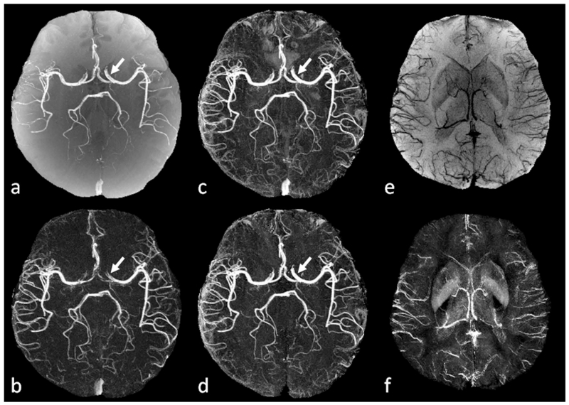
SWI data can be acquired using either a single or multi- echo sequence, with the latter providing more flexibility in choosing echo times which will affect the image contrast due to susceptibility effects (39,44–46). When multi-echo data are available, it is possible to obtain MR Angiography (MRA) and SWI simultaneously, which are both necessary to depict the cerebral vascular system morphologically and functionally (47). We have developed a new interleaved double-echo sequence with arbitrary TEs to achieve simultaneous high resolution MRA and venography (48), through enhanced time of flight (TOF) angiography and SWI, allowing clear separation of arteries and veins in a single scan. One particular advantage of this sequence is that the interleaved images are precisely aligned to each other and, hence, image registration is not required. In this sequence, two consecutive TR blocks were executed with two echoes for each block (referred to as echo11, echo12, echo21 and echo22). Specifically, echo11 echo12, and echo21 are flow rephased using first order moment nulling gradients. On the other hand, echo22 is flow dephased using bipolar gradients with a low VENC value. A conventional TOF-MRA image can be generated as the average of echo11 and echo21. While echo12 provides the SWI image, echo22 provides the dark blood image. A direct subtraction between echo12 and echo22 removes the background tissues, leading to an enhanced MRA image (since the veins are dark in both images), as shown in Figure 5. Although the visualization of small vessels with slow blood flow is excellent, the longer echo times sometimes have difficulties portraying the larger arteries with fast flow near the sinuses, because of the presence of background field gradients that destroy the flow compensation (29). To overcome this problem, another enhanced MRA image can be obtained from a linear subtraction between the TOF-MRA (average of echo11 and echo21) and the flow dephased second echo (echo22) as (echo11+echo21)/2−λecho22, where λ was set to 1.3 to compensate for the T2* signal decay at the longer echo. Finally, utilizing the magnitude, phase and susceptibility maps, the veins can be suppressed and an improved MRA image can be obtained. Now there is no difficulty in visualizing the major arteries such as the internal carotid arteries and the middle cerebral arteries (Figure 5.d), because of the use of the shorter echo which leads to better flow compensation.
Figure 5.
Simultaneous MRA, SWI and QSM using the interleaved double-echo sequence. Data were collected on a Siemens 3T Verio system using a 32 channel head coil, with TE1/TE2/TR=6/19.2/24ms, FA=15° and voxel size 0.6×0.6×1.2mm3. a. TOF-MRA generated as the average of echo11 and echo21. b. Enhanced MRA by subtracting echo22 from echo12. c. Enhanced MRA by subtracting echo22 from a (TOF-MRA). d. Enhanced MRA after venous structures were removed from c. e. Minimum intensity projection of SWI data generated from echo12. f. Maximum intensity projection of susceptibility maps generated from echo12, using the geometry constrained iterative SWIM algorithm (65). Small arteries are clearer on b and d than on a. Internal cerebral arteries, middle cerebral arteries and anterior cerebral arteries are better visualized on d than on b (arrows), due to the better flow compensation at the shorter echo. See the main text for the definition of different echoes.
4. Data reconstruction
Proper reconstruction of the phase images from a gradient echo sequence is critical for both SWI and QSM, since any noise or artifact in the phase images will be propagated into the final results during the phase unwrapping and/or background phase removal (41,49,50). While SWI and QSM may be largely affected when severe signal cancelation occurs due to improper combination, local cusp artifacts could also be mis-interpreted as microbleeds (9,51).
When GRAPPA is used for parallel imaging, magnitude and phase images will be reconstructed for each channel of the phased array coil and then combined to generate the final images (52–54). The optimal combination requires knowledge of the coil sensitivities which are usually not available (55–58). Using the conjugates of the complex data as an approximation of the coil sensitivity leads to the sum-of-squares combination which provides a near optimal combination of the multichannel data when SNR is sufficiently high (55). For phase images, however, a simple magnitude weighted averaging of the complex data may lead to phase singularities/cusp artifacts in the combined phase images, mainly attributed to the variation in the coil sensitivity induced phase components between different coils/channels (53,54,59–61). Based on Eq. 1, the phase from channel j in a left-handed system can be written as:
| [5], |
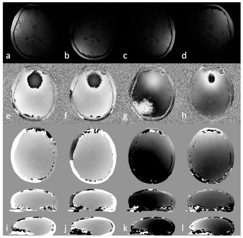
where ϕ0,j(r) is the coil sensitivity dependent phase. A commonly used strategy is to model the ϕ0,j(r) as a constant and the baseline of the phase images in each channel is registered to that of a selected reference channel, where the baseline is estimated using central voxels with sufficiently high SNR (53). This approach, referred to as the constant phase offset algorithm in this paper, eliminates cusp artifacts in the central part of the field of view. However, the quality of the combined phase images will be dependent on the selected region since ϕ0,j(r) is not spatially uniform, as demonstrated in Figure 6. A more sophisticated approach is to use either a body coil or multi-echo data to calculate ϕ0,j(r) explicitly (54,60). Specifically, when a double-echo sequence is used,
| [6]. |
Figure 6.
Magnitude images (a to d), phase images (e to h) and the estimated coil sensitivity related phase in different views (i to l) for 4 different channels (columns). See the main text for details of the calculation of the coil sensitivity related phase. Images in sagittal view were scaled for better visualization. Multi-channel data combination without considering the variation in the sensitivity related phase components between different channels leads to singularities or cusp artifacts in the combined phase images.
However, this approach requires extra scans/echoes and time-consuming data processing such as unwrapping the phase of every channel (54). In this paper, we demonstrate an improved algorithm over the constant phase offset algorithm, referred to as echo center correction (ECC) algorithm. Particularly, the coil sensitivity induced phase component (Figure 6) is modeled as a 3D linear function which can be determined and corrected effectively in k-space (12,62). This is particularly convenient for integrating this algorithm into the image reconstruction pipeline of the MR scanner. When modeled as a 3D linear function, ϕ0,j(r) can be approximated as:
| [7]. |
The gradient βj = [βx,j, βy,j, βz,j] can be estimated from the position of the element with maximum magnitude value in k-space (denoted as kmax,j), using the Fourier shift theorem, while the constant phase offset ϕc,j can be estimated from ϕc,j = arg (kmax,j). After that, can be removed from the original phase images through complex division. In order to improve the accuracy of estimating the linear gradients, the central part of k-space can be interpolated by a factor of 2, through zero-filling in the image domain. Also note that it is only the peak of k-space that is of importance to this algorithm. Hence, the proposed algorithm can be applied using only the data in the central part of k-space, which also makes this algorithm both memory and time efficient. Finally, the phase images from all the N channels can be combined by averaging the complex data, weighted by the square of the magnitude:
| [8]. |
The proposed algorithm was tested using in vivo data collected on a 3T Siemens system equipped with a 32-channel head coil, using a fully flow compensated double-echo sequence with the following imaging parameters: TE1=7.38ms, TE2=17.6ms, TR=30ms, FA=15°, BW/px=425Hz/px, voxel size=0.6×0.6×1.2mm3, matrix size=512×368×144, GRAPPA acceleration factor=2. In order to compare different coil combination algorithms, the phase images were combined using: 1) simple magnitude weighted averaging; 2) the constant phase offset algorithm, in which the differences between the ϕ0,j(r) in each channel and the user-defined reference channel were estimated from 32×32×32 central voxels in image domain; 3) the double-echo phase combination: ϕ0,j(r) was obtained using Eq. 6 for each channel (a 5×5×5 median filter was applied to ϕ0,j(r), in order to reduce the random noise. Then the phase images were created following Eq. 8 for each echo); 4) the proposed ECC algorithm; and 5) a channel-by-channel high-pass filtering: 2D homodyne high-pass filter with k-space window size 64×64 was applied to the phase images of each channel, and then the filtered phase images were combined using magnitude weighted averaging similar to Eq. 8. For generating SWI and QSM data, the phase images combined using algorithm 5 were used directly, without further phase unwrapping or background phase removal, since the combined phase images were effectively high-pass filtered already. On the other hand, background phase removal is still required prior to generating the SWI and QSM data using the phase images combined through algorithms 1 to 4. For generating SWI data, homodyne high-pass filter (with 64×64 k-space window size) was applied. For generating QSM data, Laplacian phase unwrapping (9) was used for the phase images combined using algorithm 1, for better handling of the expected cusp artifacts; while 3D path-following phase unwrapping (63) was used for the phase images combined using algorithms 2 to 4. Next, SHARP was applied to remove the background phase and a geometry constrained iterative SWIM algorithm (64,65) was used to generate the susceptibility maps.
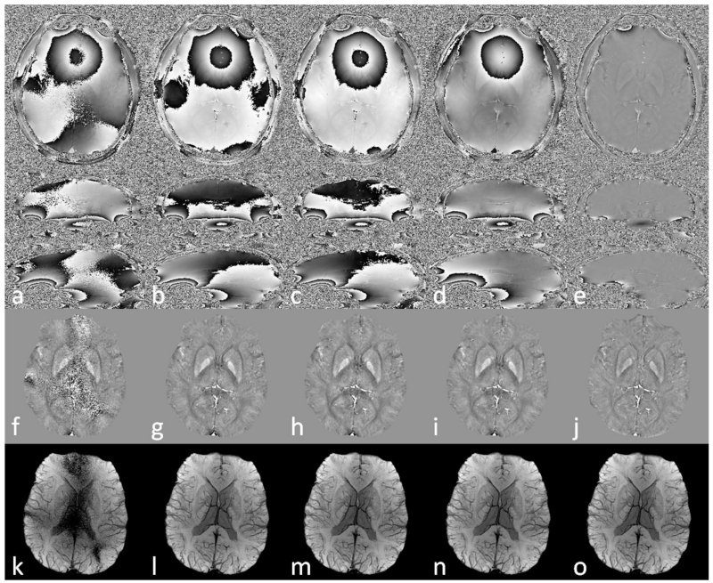
As shown in Figure 7, a simple magnitude weighted combination without considering the coil-sensitivity related phase components resulted in reduced SNR and cusp artifacts in the combined phase images. These artifacts propagated into QSM and SWI data. Using constant phase offset, double-echo combination and ECC algorithms, cusp artifacts were avoided from the combined phase images, leading to significantly improved quality in both QSM and SWI data. Comparing all the combined phase images in Figure 7, it can be concluded that the ECC algorithm eliminated the cusp artifacts and provided phase images with the most uniform profile, reflecting the proper handling of the coil sensitivity related phase components. On the other hand, the constant phase offset did not account for the spatial variation of the coil sensitivity and the combination was affected by the choice of the reference channel. Although ϕ0,j(r) was determined using the double-echo method, the combined phase images had slightly lower SNR due to the noise amplification through Eqs. 6 and 8. It is also assumed that the ϕ0,j(r) terms in different echoes are the same, without any additional background phase components such as those induced by eddy current effects; while the ECC algorithm can correct any linear background phase. This explains the differences between the results obtained using the double-echo combination and using the ECC combination. When a homodyne high-pass filter was applied to each channel prior to the combination, the combined phase images were not affected by cusp artifacts. However, this caused signal loss to the local phase and under-estimation in susceptibility quantification. For SWI, either the ECC algorithm or the channel-by-channel high pass filtering algorithm can be used.
Figure 7.
Comparison of the effects of different multi-channel data combination algorithms on phase images (a to e), QSM (f to j) and SWI (k to o). a, f, k: simple magnitude weighted averaging. b, g, i: constant phase offset algorithm. c, h, m: double-echo phase combination. d, i, n: echo center correction (ECC) algorithm. e, j, o: channel-by-channel high-pass filtering. Data were collected using a double-echo sequence with TE1=7.38ms and TE2=17.6ms. Only the results correspond to TE2 are shown here.
5. Clinical applications of SWI
5.1. Imaging stroke
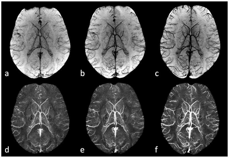
One of the most important recent applications of SWI is imaging stroke. It is well known that reliable detection of the ischemic penumbra has a significant impact on treatment and management, especially for acute stroke patients who might benefit from the thrombolytic therapy (66–69). The DWI-PWI mismatch is generally considered as the indicator of salvageable brain tissue with hypo-perfusion but preserved metabolic rate, despite the limitations such as the imprecise definition of perfusion deficit (68–74). In order to improve the detection of the penumbra, newer methods have been proposed exploiting T2* signal variation due to the change in deoxyhemoglobin/hemoglobin ratio, based on the fact that the oxygen extraction fraction in the ischemic penumbra is increased as a compensatory mechanism in response to misery perfusion (73–76). Because of its utilization of phase information, which is exquisitely sensitive to the changes in oxygen saturation of the blood, SWI could be a powerful tool for better detection of the ischemic penumbra (69,77). The potential of using SWI to image cerebral venous oxygen saturation is demonstrated in Figure 8 in which a clear trend of enhancing visibility of the veins on SWI can be observed, accompanied by increasing susceptibilities of the veins on QSM, from post acetazolamide administration, to normal state, and then to post caffeine administration, reflecting the increasing deoxyhemoglobin concentration in the veins.
Figure 8.
Imaging cerebral venous oxygen saturation under different conditions using SWI and QSM. a and d: post acetazolamide administration. b and e: normal state. c and f: post caffeine administration. Here a to c are the minimum intensity projections of SWI, while d to f are the maximum intensity projections of the susceptibility maps generated using the geometry constrained iterative SWIM algorithm (65). The effective slice thickness is 20mm for all the images. Both the enhanced visibility of the veins on SWI from a to c and the increased susceptibilities on QSM from d to f reflect the increasing concentration of deoxyhemoglobin in the veins. The data for the acetazolamide and caffeine experiments were collected on different days, while the data for the normal state were collected before the caffeine administration during the caffeine experiment.
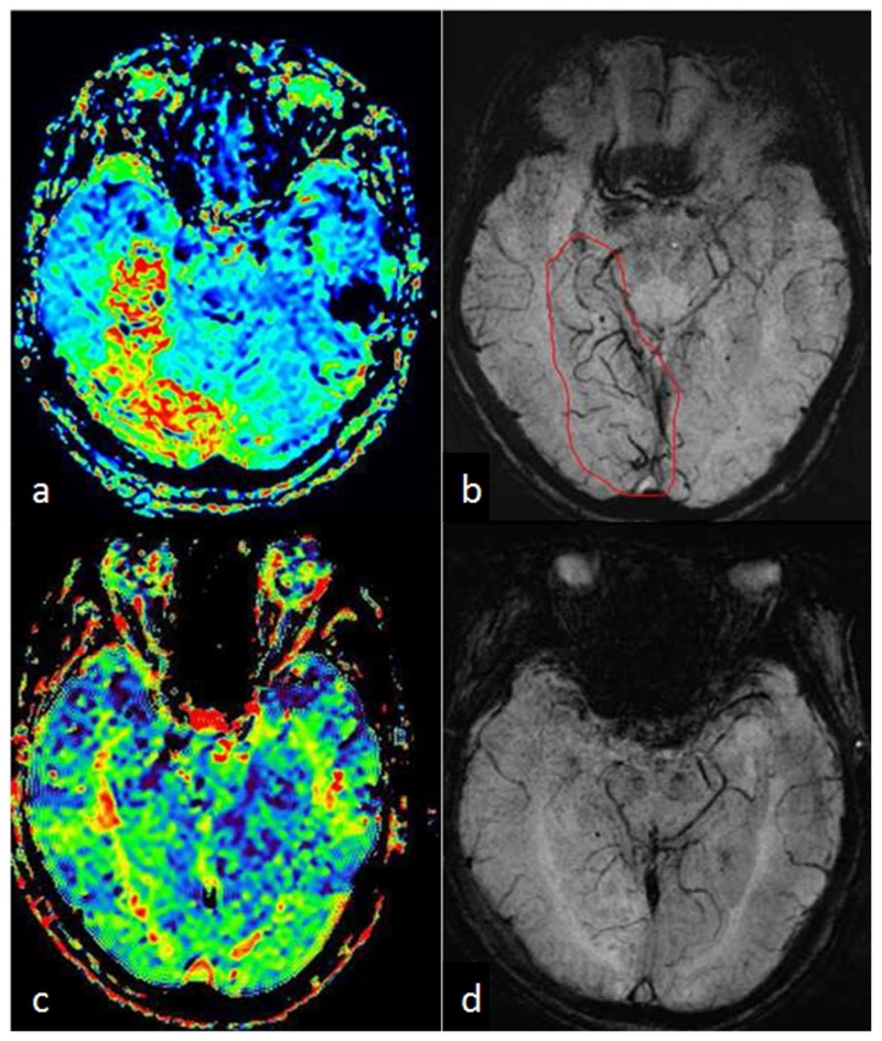
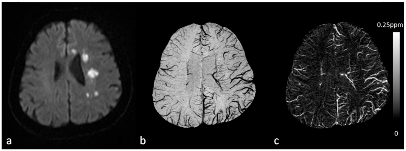
In fact, asymmetrically prominent cortical veins (APCVs) are usually observed on SWI in stroke patients, even in regions outside those with restricted diffusion on DWI (78–87). This is referred to as the DWI-SWI mismatch. Furthermore, it was found that the DWI-SWI mismatch correlates with the DWI-PWI mismatch and SWI could be a surrogate for PWI (80,81,86), as shown in the example in Figure 9. However, this correlation could be compromised in the presence of leptomeningeal arterial collateralization (84). Consequently, SWI could be an important technique in stroke imaging which provides high resolution local information of the oxygen extraction fraction yet does not require the use of a contrast agent. Nevertheless, further studies which include a sufficient number of subjects are still required.
Figure 9.
A 77-year-old male who suddenly had left limb weakness and paresthesia underwent an MR scan with PWI and SWI 3 hours after stroke. MTT (a) showed a large hypo-perfused region in the right lateral hippocampus and occipital lobe, while SWI (b) showed asymmetrically prominent cortical veins (APCV) in the corresponding region, as indicated by the red contour in b. Six days after intravenous rTPA treatment, with improved neurological symptoms, the patient underwent a second MR scan with PWI-MTT (c) and SWI (d), in which both MTT and SWI appeared normal.
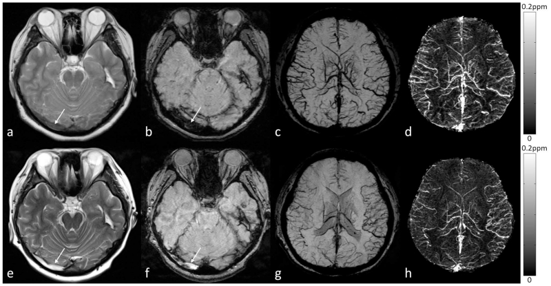
Moreover, the accuracy of detecting the penumbra using SWI could be affected by the orientation of the veins and imaging parameters (26). This problem can be solved by using QSM, the quantitative version of SWI (9,26). The potential of QSM has been demonstrated in a recent study, in which Xia et al. (88) compared the susceptibility value of cortical veins in the left and right hemispheres of healthy controls as well as in the contralateral hemisphere of stroke patients with APCVs. It was concluded that the occurrence of APCVs in ischemic stroke patients in SWI data was best explained by the increased deoxyhemoglobin concentration in the APCVs. In that study, a 16% to 44% decrease of the oxygen saturation of the APCVs was found, compared with that in the contralateral hemisphere (Figure 10). SWI has also been used to detect occlusive arterial thromboemboli (87,89,90). The sensitivity of SWI to arterial thrombus was found to be better than both CT and FLAIR images (89,90). In the disease of venous occlusion, there is collateral circulation and decreased oxygen saturation in the veins (91,92), as shown in Figure 11. The increased cerebral venous oxygen saturation may correspond to early recanalization or collateral venous drainage.
Figure 10.
Visualization and quantification of asymmetrically prominent cortical veins (APCV) in an ischemic stroke patient using SWI and QSM. a. DWI showed multiple high signal regions in the centrum semiovale and in the genu of the corpus callosum. b. Visualization of the APCV in the left hemisphere in the minimum intensity projection of SWI data. c. Maximum intensity projection of susceptibility maps showing cortical veins with increased susceptibility in the ischemic hemisphere, compared to those in the contralateral hemisphere. Susceptibility maps were generated using the geometry constrained iterative SWIM algorithm (65).
Figure 11.
Visualization and quantification of the susceptibility of bilateral cortical veins in a 19-year-old female patient with right transverse sinus thrombosis. The right transverse sinus is less hypo-intense than normal on T2WI (a) and markedly hypo-intense and dilated on SWI (b), suggestive of early thrombosis. Bilateral cortical veins were dilated and increased levels of deoxyhemoglobin were indicated on the minimum intensity projection (mIP) of the SWI data (c) and the maximum intensity projection (MIP) of the QSM data (d). In the follow-up scan, both the T2WI (e) and the original magnitude image in the SWI data (f) showed hyper-intensity in the right transverse sinus, possibly due to evolving blood products in the thrombus (white arrows). Although a normal flow void did not return on T2WI, the increased oxygen saturation of the cortical veins may suggest early recanalization or collateral venous drainage in the brain, as indicated by both the mIP of SWI data (g) and the MIP of QSM data (h). For a to d, the original data were acquired at 1.5T (where the echo time of the SWI data was 40ms); while for e to h, the original data were acquired at 3T (where the echo time of the SWI data was 20ms). Susceptibility maps in d and h were generated using a truncated k-space division algorithm (64) with a k-space threshold 0.2. The effective slice thickness is 24mm in c, d g, and h.
5.2. Imaging microbleeds with SWI
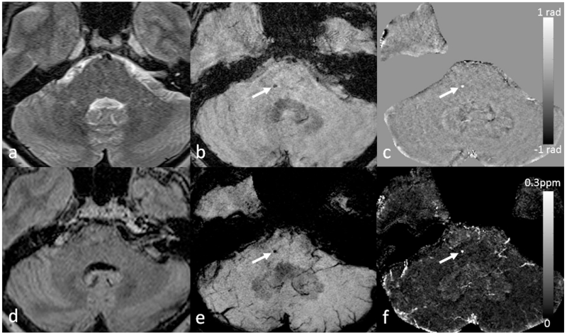
Cerebral microbleeds (CMBs), “small foci of chronic blood products in normal or near normal brain tissue” as described by Greenberg et al. (93), are commonly seen as round hypo-intense signal void on T2* weighted images (T2*WI). Multiple studies have shown that SWI is much more sensitive in detecting the presence of CMB than standard gradient-echo sequences (94–98). This is largely due to the sensitivity of SWI to blood products, the higher resolution in which SWI is usually collected, and the increased contrast SWI provides between normal parenchymal tissue and abnormal iron deposition (8,41). The detection of CMBs is usually based on the shape and the characteristics of the signal, such as signal intensity and blooming effects (93,99). Although the size of bleeding ranges between micro and macro hemorrhages, it is generally agreed that CMB can be defined as having a diameter of less than roughly 5mm (93). Other criteria based on T1 or T2 weighted images as well as the clinical history also help to improve the detection (93,100). In fact, the appearance of candidate CMBs are best confirmed when all components of SWI data (i.e., magnitude and phase images) are reviewed simultaneously, as demonstrated in Figure 12. The CMB should be partly surrounded by normal parenchyma and should be independent of vascular structures. In the phase image, a paramagnetic dipole effect should be associated with the CMB, and when reconstructed using QSM it should appear bright or highly paramagnetic. This differentiates CMBs from calcification which is diamagnetic (101). It should also be noted that the detection of CMBs may also depend on the imaging parameters such as field strength, echo time, and imaging resolution (93,102–104). While the first two parameters determine the phase information and blooming effects, imaging resolution may affect the accuracy of CMB detection through partial volume effects (9).
Figure 12.
Imaging cerebral microbleeds (CMB) using SWI and QSM. For this patient, there is a single CMB that is not visible in either T2WI (a) or FLAIR (d), but can be seen in the original magnitude (b) and filtered phase images (c) in the SWI data (white arrows). The CMB can be better visualized in the minimum intensity projection of SWI data (e) and the maximum intensity projection of susceptibility maps (f) (white arrows). The CMB appears as hypo-intense in b and e, while hyper-intense in c and f, indicating that it is paramagnetic. Note that the phase image shown in c was from a left-handed system. There is no connection between the CMB and vessels, as can be seen in both e and f. Susceptibility maps were generated using the geometry constrained iterative SWIM algorithm (65). The (effective) slice thickness is 2mm in a, 1.5mm in b and c, 0.5mm in d, 12mm in e and f.
Several diseases have benefitted from the use of SWI as a means for detecting CMB, including traumatic brain injury (TBI), stroke, and dementia (93,105–109). In TBI, Spitz et al. demonstrated that SWI detected far more TBI related lesions than FLAIR (110). In addition, it was found that the lesion volume on SWI correlated with the severity of the injury, while the lesion volume on FLAIR did not, although the lesion volumes measured by both techniques did show a positive correlation with the cognitive impairment. Liu et al. also demonstrated in a military cohort that had experienced TBI, SWI was the most effective method available compared to conventional MRI scanning to detect CMB. In their study, 77% of CMB appeared more clearly on SWI than on conventional MRI (111). This finding in the detection of CMB is quite common. While standard 2D gradient-echo sequence may find similar results in the prevalence of a sample who are CMB positive, the actual count of CMB which are identified using SWI may be almost doubled compared with 2D gradient-echo sequence (96,103,112). In addition to the detection of primary CMBs, SWI may also be used to evaluate the secondary CMBs and the oxygen saturation of local veins in areas suffered from ischemic hypo-perfusion due to diffuse axonal injury associated with head trauma (113,114), as shown in Figure 13. It was found that the susceptibilities of small hemorrhages were significantly higher than that of major veins, with a susceptibility threshold of 200ppb giving 92% for both sensitivity and specificity (114). In stroke, the presence of CMB must be evaluated for thrombolytic therapy to prevent secondary symptomatic intracranial hemorrhage (ICH). It was shown that SWI provide critical information for the treatment planning of antiplatelet therapy (115). It was also found that in patients affected by ischemic stroke or transient ischemic attack, multiple CMBs were associated with significantly increased risk of future ICH (116). The location of the CMBs may be associated with different pathologies, with deep CMBs being related to hypertensive vasculopathy while lobar CMBs being related to cerebral amyloid angiopathy (CAA) (93). For example, the presence of multiple or mixed CMBs was found to be correlated with increased risk in dementia (117,118). Even in normal elderly people with incidental cortical CMBs, significantly reduced cerebral blood flow (CBF) was observed which may be associated with increased risk of neurodegeneration (119). The increased rate of CMB proliferation can also be used as a method of diagnosis (106). In summary, the accurate detection and quantification of microbleeds is critical to the patient’s diagnosis and prognosis.
Figure 13.
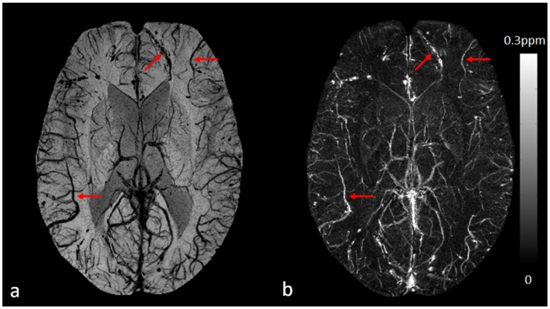
Visualization and quantification of cortical veins on SWI (a) and QSM (b) in a 32-year-old male patient with diffuse axonal injury due to a traffic accident. The cortical veins near the cerebral microbleeds can be clearly seen in the frontal and parietal lobes (red arrows). Susceptibility maps were generated using the geometry constrained iterative SWIM algorithm (65).
5.3. Imaging the carotid vessel wall
Stroke is the second leading cause of death in the world, and carotid artery disease is one of most common causes of ischemic stroke (120,121). Symptomatic patients with high grade carotid stenosis may have vulnerable carotid plaques, as found in randomized controlled studies, the North American Symptomatic Carotid Endarterectomy Trial (NASCET) (122) and the European Carotid Surgery Trial (ECST) (123). However, vulnerable carotid plaques are not visible in angiography. Therefore, vessel wall imaging is indispensable for both the diagnosis and monitoring of treatment responses. In the field of cardiovascular disease, plaques with high-grade stenosis may not cause cardiovascular events, but those with low-grade stenosis may cause stroke (124). Better predictions of cardiovascular events can be achieved using carotid vessel wall imaging combined with the Framingham risk factors, including old age, male gender, high total cholesterol, low high-density lipoprotein (HDL), smoking, and high systolic blood pressure (125,126).
Both ultrasound and computed tomography (CT) have been applied to imaging carotid vessel wall. Using ultrasound, it is found that lipid-rich necrotic core and intraplaque hemorrhage (IPH) are components of vulnerable plaques, and echo lucent plaques are associated with high risk of stroke (127). Another important finding of vulnerable plaque is that the vasovasorum-derived neovascularization, which comes from inflammation, is well correlated with findings of contrast-enhanced ultrasound (128). However, ultrasound has limitations in evaluation of densely calcified plaques due to a limited acoustic window beyond calcification. Although CT is generally considered to be the best modality for imaging calcification, it has low CNR for soft tissue. Using a combination of MR sequences such as TOF-MRA, T1WI, T2WI, and proton density weighted imaging, advanced lesions can be distinguished from early and intermediate atherosclerotic plaques (129), and the results showed good correlation with the histological studies on carotid endarterectomy specimens (130).
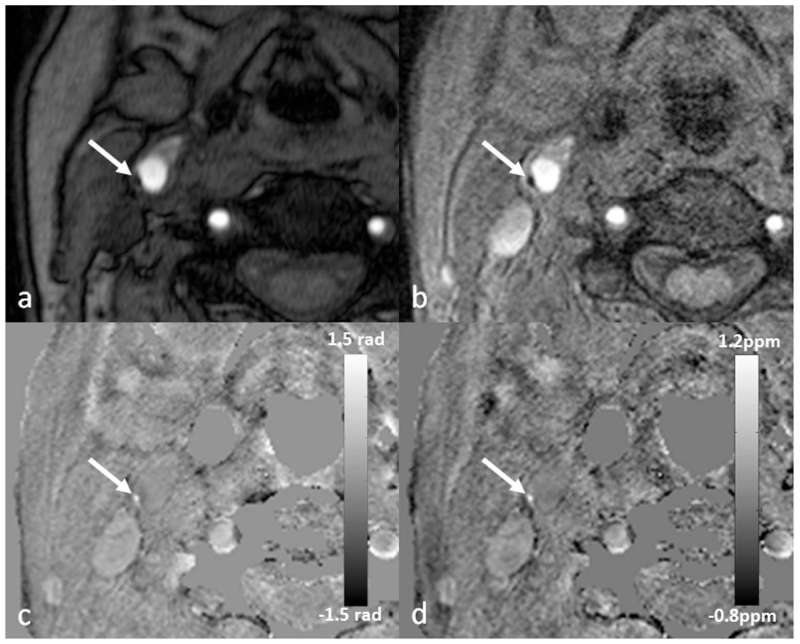
Nonetheless, for imaging complex plaques with features of large lipid-rich core, IPH, neovascularization, and inflammation (131–134), SWI has unique advantages over conventional techniques. IPH is usually defined as a two-fold hyper-intense signal within the carotid wall compared with adjacent sternocleidomastoid muscle. Normal vessel walls and calcification are diamagnetic (20,135), while IPH is paramagnetic. This leads to opposite phase polarities, which could be utilized in SWI and QSM for better differentiation of calcification from IPH (41,136,137). Although the detection and quantification of tiny foci of hemorrhage in asymptomatic carotid plaque is now possible using SWI (Figure 14), more research should be performed to investigate the sensitivity and specificity of SWI for imaging carotid plaques.
Figure 14.
Eccentric wall thickening (arrow) at the posterolateral aspect of the right common carotid artery on TOF-MRA (a). There is a dark spot on the magnitude image (b), which appears bright on both the filtered phase image (c) and the susceptibility map (d). This suggests that this is a tiny foci of intraplaque hemorrhage and may represent an example of vulnerable plaque. The original data for b, c and d were acquired using a multi-echo SWI sequence at 3T, although these images were generated using the data from the shortest echo with TE=5.18ms. Image c was generated using a homodyne high-pass filter with k-space window size 64×64, while d was generated using a truncated k-space division algorithm (64) with a k-space threshold 0.2.
5.4. Imaging siderotic nodules in cirrhotic liver
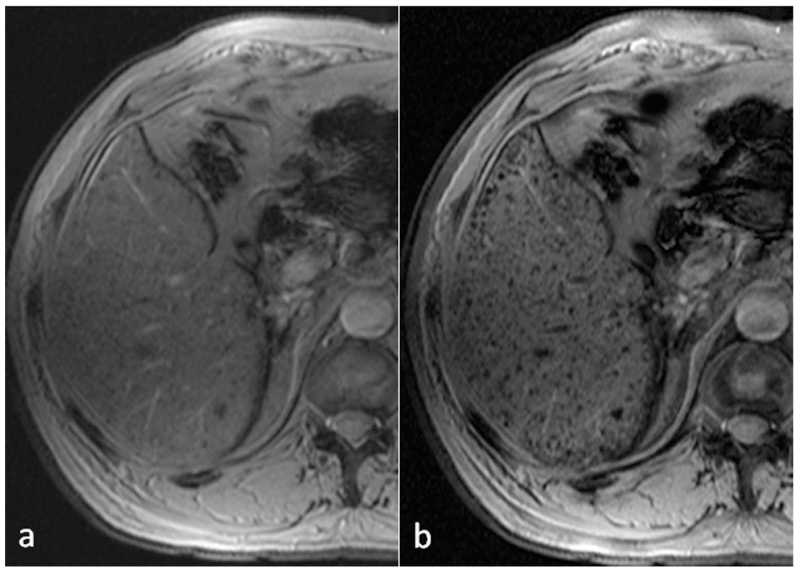
Inspired by the successful applications of SWI in neuro-imaging and motivated by the goal to improve the research and diagnosis of iron-related diseases, SWI has been extended to organs outside the brain (22,24,138,139). A typical abdominal application of SWI is imaging siderotic nodules in hepatic cirrhosis (22). It is well known that iron plays a significant role in the development of chronic hepatitis, hepatic cirrhosis, and hepatic carcinoma. For cirrhosis patients, liver iron may be accumulated within the siderotic nodules, even without iron overload disorders (22,140,141). However, the mechanism of iron deposition in the formation of siderotic nodule is still unclear, partly due to the inadequacy in detecting iron deposition in cirrhotic liver using conventional T2*WI (22), as demonstrated in Figure 15.
Figure 15.
Comparison of T2*WI (a) and SWI (b) for the detection of siderotic nodules (SN) in cirrhotic liver disease. The number of detected SN was 30 on T2*WI (a), and 139 on SWI (b). In the whole liver, the number of SN detected by SWI was nearly 5 times that detected by T2*WI (393 by T2*WI vs 1856 by SWI).
Different from the conventional three-dimensional gradient-echo sequence used in neuro-imaging, a two-dimensional multi-breath-hold gradient-echo sequence together with improved post-processing help to reduce the respiratory motion artifacts in liver imaging (22). As expected, SWI outperformed T2*WI in the detection of siderotic nodules, with SWI being approximately two times more sensitive to the presence of siderotic nodules than T2*WI. It was also observed that certain siderotic nodules with low iron content can only be detected by SWI. Besides the detection of siderotic nodules, SWI has been applied to detecting hemorrhage in hepatic lesions and grading liver cirrhosis (138,142). Using the phase information or the derived susceptibility distribution, it is also possible to quantify liver iron concentration using SWI and QSM (143,144).
5.5. Imaging prostate cancer and prostatic calcification
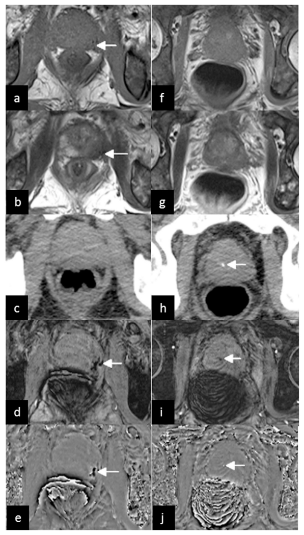
SWI has also been used to detect hemorrhage in prostate cancer and to measure prostatic calcification (145). Prostate cancer, commonly found in elderly men, has now become one of the major challenges to public health (146). Conventional MRI techniques (T1WI and T2WI) have been useful in detecting prostate cancer, despite the low specificity in distinguishing prostate cancer from benign prostatic diseases, especially in the prostate peripheral zone (145). Since prostate cancer tissues are prone to bleeding whereas noncancerous tissues are not, SWI may provide important information for the differentiation of prostate cancer from benign diseases. As reported in Bai et al. (145), most patients with prostate cancers had hemorrhages (Figure 16), whereas hardly any hemorrhage was detected in the noncancerous prostates. Using the hemorrhage of prostate on SWI as a biomarker, their results revealed higher sensitivity and specificity for SWI than conventional MRI in the diagnosis of prostate cancer.
Figure 16.
A 66-year-old man with prostate cancer in the peripheral zone of the prostate. Low signal on conventional T1WI (a) and T2WI (b) (arrows) indicates tumor hemorrhage. No hemorrhage is demonstrated on CT (c). The tumor hemorrhage was seen with SWI (d) and the filtered phase image (e) (arrows). The images in the second column came from another slice of the same patient. No prostatic calcification is demonstrated on conventional T1WI (f) and T2WI (g), but a dot-like high density on CT (h), low signal on SWI (i) and high signal on the filtered phase image (j) (arrows) indicates calcification. The filtered phase images (e and j) were from a right-handed system. Reproduced from ref. (145).
Prostatic calcifications were associated with several urological diseases and symptoms (147). Traditionally, CT has been used as the gold standard in detecting calcification. Nowadays, MRI is more commonly used in the prostate examination than CT because of its better soft tissue contrast. However, due to the complicated components and various proportions in calcification, the signal intensity of calcification on conventional T1WI and T2WI may vary greatly (148,149), making it difficult to detect prostatic calcification using conventional MRI techniques. Fortunately, the paramagnetic and diamagnetic materials have opposite signal intensities in filtered phase images (8,9). This enables the easy differentiation of calcification from hemorrhage using SWI and QSM (18,101,150). It has been shown that the filtered phase images could identify prostatic calcification equally well as CT, but were much better than using conventional MRI (Figure 16).
5.6. Imaging spinal cord injury
Although SWI has been shown to be far superior in detecting microbleeds compared to conventional T1WI, T2WI, or T2*WI in various conditions in the brain, such as stroke, trauma and vascular dementia etc., the susceptibility artifact renders imaging spinal cord a challenging problem. For patients with spinal cord injury (SCI), it is crucial to detect intraspinal hemorrhage for both treatment and management of the patients (151,152). The first SWI study on detecting hemorrhage in the spinal cord was performed by Wang et al. (21), in which the authors compared SWI with conventional T1WI, T2WI and T2*WI techniques. Out of the 23 patients included in that study, 6 cases with intramedullary hemorrhage were found by using either conventional MRI (T1WI, T2WI) or SWI. For another two cases, conventional T1WI and T2WI only revealed spinal cord contusion, while SWI showed low signal in the spinal cord which indicated intraspinal hemorrhage. In addition, all eight patients with hemorrhage, as demonstrated by SWI, had a poorer clinical outcome than those with spinal cord edema or contusion, which was consistent with previous studies. When comparing SWI with T2*WI, the contrast between hemorrhage to normal tissue on SWI was better than that on T2*WI, reflecting the superior sensitivity of SWI to detect intraspinal hemorrhage to the conventional imaging techniques. The ability of SWI to detect hemorrhages not seen by conventional imaging is of key importance to the prognosis for SCI patients. Moreover, this study also demonstrated the feasibility of including SWI as a routine MRI sequence for SCI patients, when the imaging parameters of SWI were properly chosen to balance the SWI data quality and acquisition time (see Table 1 for example imaging parameters).
5.7. Imaging intervertebral disc degeneration
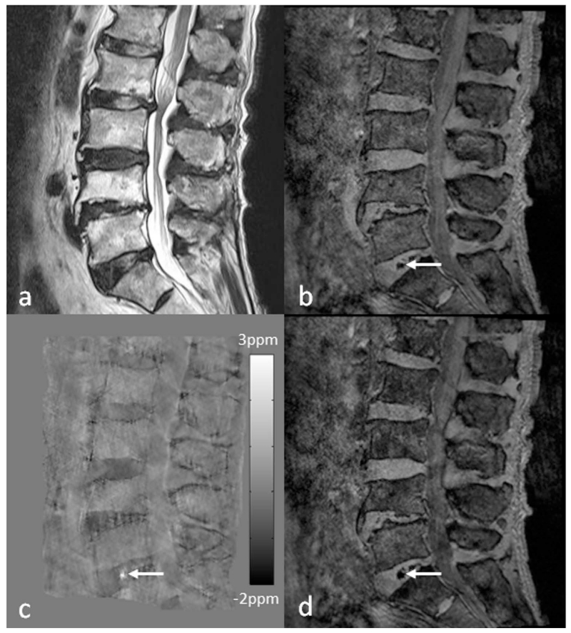
Lower back pain (LBP) is one of the most common health problems with a huge socioeconomic burden, in which intervertebral disc degeneration plays a significant role (153). It is generally acknowledged that the severity of degeneration is broadly associated with chronic symptoms (154). However, intervertebral disc degeneration is difficult to define, as it covers a variety of clinical, morphologic, and histologic manifestations. Adams et al. suggested a working definition that disc degeneration is an aberrant cell-mediated response to progressive structural failure (155). Simple as it seems, this definition connotes a wide range of changes from a biochemical level to functional consequences. During the aging process, the amount of proteoglycans and collagen type II slowly decreases with subsequent loss of water content in the nucleus pulposus, the inner gelatinous part of the disc. Meanwhile, defects or fissures develop in the annulus, the outer lamella of the disc (156,157). In contrast to normal aging, these changes manifest more rapidly and extensively in disc degeneration (156). Once a disc is structurally and functionally compromised, it further elicits the degenerative cascade, including changes of adjacent vertebral bodies, facet joints, uncovertebral joints, as well as supporting ligaments. Early change in the intervertebral disc architecture and its causal relationship with pain has been assessed with CT discography (158). However, owing to the invasiveness of the CT discography, MRI was established as a main diagnostic tool for intervertebral disc evaluation (159). Due to the differences in composition of collagen and water, nucleus pulposus and annulus fibrosus of intervertebral disc without degenerative change are clearly discriminated on T2-weighted images. As the degenerative process progresses, the distinction in signal intensity is effaced and structural changes such as bulging or height loss will appear (160). The Pfirrmann grading system of disc degeneration, which is most widely used in the clinical practice, is mainly based on the changes in T2-weighted images. However, the grading system has limitations in that it is relatively nondiscriminatory in elderly subject, and only has a weak correlation with the severity of symptoms (161). Recently, more advanced MRI techniques such as diffusion-tensor imaging, T1ρ imaging, T2 mapping, and magnetic resonance spectroscopy have been applied to intervertebral disc, in order to gain insights in the biochemical and microstructural changes of the degenerating intervertebral disc prior to the morphologic changes (162–165). The use of SWI outside the brain is usually affected by the susceptibility artifacts due to air/bone-tissue interface. In the spine, SWI has been applied for evaluating traumatic cord hemorrhage or visualizing normal spinal vein (21,166). It is also a potential tool for evaluating degenerated discs. As discs degenerate, they undergo structural deterioration as well as accumulation of materials such as calcification and air (so-called vacuum phenomenon). SWI (both magnitude blooming effects and phase) and QSM can capture and quantitatively assess those changes in the disc under the degenerative process (Figure 17).
Figure 17.
Imaging advanced intervertebral disc degeneration more than grade 4 by the Pfirrmann grading system in the lumbar spine using SWI and QSM. Intradiscal air in the L5-S1 intervertebral discs (arrows) is better visualized on the magnitude image (b), susceptibility map (c) and tSWI (d), than on T2WI (a). Susceptibility maps were generated using the geometry constrained iterative SWIM algorithm (65).
6. Future directions
The potential of SWI has already been demonstrated in clinical applications focused on the brain. Using short TEs to reduce phase aliasing and T2* signal decay, it is also possible to image the structures with high susceptibilities such as air and bone using QSM (25). Through the marriage of SWI and QSM as tSWI, the geometry dependence of conventional SWI can be avoided and more accurate delineation of these structures can be obtained (26,27). In order to further apply SWI to other organs in the body, such as liver and kidney, one of the major challenges is handling motion artifact, especially when relatively high imaging resolution is desired. Fast imaging is the key to resolving this problem. In the past few years, a few techniques have been proposed which can be used for both SWI and QSM, such as 2D and 3D echo planar imaging (EPI) (167–172). However, conventional EPI techniques are known to be prone to geometric distortion, and segmented EPI (SEPI) partly solves this problem (172,173). Using similar field of view and resolution, 3D GRE with Wave-CAIPI provides significantly accelerated data acquisition, with the benefits in reducing the distortion and preserving the SNR (174,175). Compressed sensing (CS) has also been tested for both SWI and QSM. While the feasibility of applying CS to SWI data acquisition has been demonstrated, the reconstructed phase images may lead to additional artifacts in the susceptibility maps in QSM and better reconstruction algorithms are still needed (176–178). These techniques may play a significant role in the future applications of SWI, and will open the door for abdominal imaging using SWI such as fetal brain imaging (179–181).
Acknowledgement
This work was supported in part by the Canadian Institutes of Health Research/Heart and Stroke Foundation of Canada Synchrotron Medical Imaging Team Grant under award number CIF 99472, the Telemedicine and Advanced Technology Research Center (TATRC) at the U.S. Army Medical Research and Materiel Command (USAMRMC) under award number W81XWH-12-1-0522, and the National Cancer Institute, NIH, through Grant Number R21CA184682. Its contents are solely the responsibility of the authors and do not necessarily represent the official views of the NIH. The views, opinions and/or findings contained in this report are those of the author(s) and should not be construed as an official government position, policy or decision unless so designated by other documentation.
Abbreviations
- APCV
asymmetrically prominent cortical veins
- CAA
cerebral amyloid angiopathy
- CAIPI
controlled aliasing in parallel imaging
- CBF
cerebral blood flow
- CMB
cerebral microbleed
- CNR
contrast-to-noise ratio
- CS
compressed sensing
- CT
computed tomography
- DWI
diffusion weighted imaging
- ECC
echo center correction
- ECST
European Carotid Surgery Trial
- EPI
echo planar imaging
- FLAIR
fluid-attenuated inversion recovery
- GRAPPA
generalized autocalibrating partially parallel acquisitions
- HDL
high-density lipoprotein
- ICH
intracranial hemorrhage
- IPH
intraplaque hemorrhage
- LBP
lower back pain
- MRA
magnetic resonance angiography
- MTT
mean transit time
- NASCET
North American Symptomatic Carotid Endarterectomy Trial
- PWI
perfusion weighted imaging
- QSM
quantitative susceptibility mapping
- SCI
spinal cord injury
- SEPI
segmented echo planar imaging
- SHARP
sophisticated harmonic artifact reduction for phase data
- SN
siderotic nodules
- SNR
signal-to-noise ratio
- SWI
susceptibility weighted imaging
- SWIM
susceptibility weighted imaging and mapping
- TBI
traumatic brain injury
- T1WI
T1 weighted imaging
- T2WI
T2 weighted imaging
- T2*WI
T2* weighted imaging
- TOF
time of flight
- tSWI
true susceptibility weighted imaging
- VENC
velocity encoding
References
- 1.Haacke EM, Lai S, Yablonskiy DA, Lin W. In vivo validation of the bold mechanism: A review of signal changes in gradient echo functional MRI in the presence of flow. Int J Imaging Syst Technol. 1995;6(2-3):153–63. [Google Scholar]
- 2.Haacke EM, Lai S, Reichenbach JR, Kuppusamy K, Hoogenraad FG, Takeichi H, Lin W. In vivo measurement of blood oxygen saturation using magnetic resonance imaging: a direct validation of the blood oxygen level-dependent concept in functional brain imaging. Hum Brain Mapp. 1997;5(5):341–6. doi: 10.1002/(SICI)1097-0193(1997)5:5<341::AID-HBM2>3.0.CO;2-3. [DOI] [PubMed] [Google Scholar]
- 3.Reichenbach JR, Venkatesan R, Schillinger DJ, Kido DK, Haacke EM. Small vessels in the human brain: MR venography with deoxyhemoglobin as an intrinsic contrast agent. Radiology. 1997;204(1):272–7. doi: 10.1148/radiology.204.1.9205259. [DOI] [PubMed] [Google Scholar]
- 4.Reichenbach JR, Essig M, Haacke EM, Lee BC, Przetak C, Kaiser WA, Schad LR. High-resolution venography of the brain using magnetic resonance imaging. MAGMA. 1998;6(1):62–9. doi: 10.1007/BF02662513. [DOI] [PubMed] [Google Scholar]
- 5.Reichenbach JR, Barth M, Haacke EM, Klarhöfer M, Kaiser WA, Moser E. High-resolution MR venography at 3.0 Tesla. J Comput Assist Tomogr. 2000;24(6):949–57. doi: 10.1097/00004728-200011000-00023. [DOI] [PubMed] [Google Scholar]
- 6.Reichenbach JR, Jonetz-Mentzel L, Fitzek C, Haacke EM, Kido DK, Lee BC, Kaiser WA. High-resolution blood oxygen-level dependent MR venography (HRBV): a new technique. Neuroradiology. 2001;43(5):364–9. doi: 10.1007/s002340000503. [DOI] [PubMed] [Google Scholar]
- 7.Reichenbach JR, Haacke EM. High-resolution BOLD venographic imaging: a window into brain function. NMR Biomed. 2001;14(7-8):453–67. doi: 10.1002/nbm.722. [DOI] [PubMed] [Google Scholar]
- 8.Haacke EM, Xu Y, Cheng YN, Reichenbach JR. Susceptibility weighted imaging (SWI) Magn Reson Med. 2004;52(3):612–8. doi: 10.1002/mrm.20198. [DOI] [PubMed] [Google Scholar]
- 9.Haacke EM, Liu S, Buch S, Zheng W, Wu D, Ye Y. Quantitative susceptibility mapping: current status and future directions. Magn Reson Imaging. 2015;33(1):1–25. doi: 10.1016/j.mri.2014.09.004. [DOI] [PubMed] [Google Scholar]
- 10.Wang Y, Liu T. Quantitative susceptibility mapping (QSM): Decoding MRI data for a tissue magnetic biomarker. Magn Reson Med. 2015;73(1):82–101. doi: 10.1002/mrm.25358. [DOI] [PMC free article] [PubMed] [Google Scholar]
- 11.Liu C, Li W, Tong KA, Yeom KW, Kuzminski S. Susceptibility-weighted imaging and quantitative susceptibility mapping in the brain. J Magn Reson Imaging. 2015;42(1):23–41. doi: 10.1002/jmri.24768. [DOI] [PMC free article] [PubMed] [Google Scholar]
- 12.Haacke EM, Brown RW, Thompson MR, Venkatesan R. Magnetic Resonance Imaging: Physical Principles and Sequence Design. 1st ed. Wiley-Liss; New York, NY: 1999. [Google Scholar]
- 13.Ge Y, Zohrabian VM, Osa E-O, Xu J, Jaggi H, Herbert J, Haacke EM, Grossman RI. Diminished visibility of cerebral venous vasculature in multiple sclerosis by susceptibility-weighted imaging at 3.0 Tesla. J Magn Reson Imaging. 2009 May;29(5):1190–4. doi: 10.1002/jmri.21758. [DOI] [PMC free article] [PubMed] [Google Scholar]
- 14.Chang K, Barnes S, Haacke EM, Grossman RI, Ge Y. Imaging the effects of oxygen saturation changes in voluntary apnea and hyperventilation on susceptibility-weighted imaging. AJNR Am J Neuroradiol. 2014;35(6):1091–5. doi: 10.3174/ajnr.A3818. [DOI] [PMC free article] [PubMed] [Google Scholar]
- 15.Haacke EM, Cheng NYC, House MJ, Liu Q, Neelavalli J, Ogg RJ, Khan A, Ayaz M, Kirsch W, Obenaus A. Imaging iron stores in the brain using magnetic resonance imaging. Magn Reson Imaging. 2005;23(1):1–25. doi: 10.1016/j.mri.2004.10.001. [DOI] [PubMed] [Google Scholar]
- 16.Haacke EM, Ayaz M, Khan A, Manova ES, Krishnamurthy B, Gollapalli L, Ciulla C, Kim I, Petersen F, Kirsch W. Establishing a baseline phase behavior in magnetic resonance imaging to determine normal vs. abnormal iron content in the brain. J Magn Reson Imaging. 2007;26(2):256–64. doi: 10.1002/jmri.22987. [DOI] [PubMed] [Google Scholar]
- 17.Haacke EM, Makki M, Ge Y, Maheshwari M, Sehgal V, Hu J, Selvan M, Wu Z, Latif Z, Xuan Y, Khan O, Garbern J, Grossman RI. Characterizing iron deposition in multiple sclerosis lesions using susceptibility weighted imaging. J Magn Reson Imaging. 2009;29(3):537–44. doi: 10.1002/jmri.21676. [DOI] [PMC free article] [PubMed] [Google Scholar]
- 18.Wu Z, Mittal S, Kish K, Yu Y, Hu J, Haacke EM. Identification of calcification with MRI using susceptibility-weighted imaging: a case study. J Magn Reson Imaging. 2009;29(1):177–82. doi: 10.1002/jmri.21617. [DOI] [PMC free article] [PubMed] [Google Scholar]
- 19.Wu J, Tarabishy B, Hu J, Miao Y, Cai Z, Xuan Y, Behen M, Li M, Ye Y, Shoskey R, Haacke EM, Juhász C. Cortical calcification in Sturge-Weber Syndrome on MRI-SWI: relation to brain perfusion status and seizure severity. J Magn Reson Imaging. 2011;34(4):791–8. doi: 10.1002/jmri.22687. [DOI] [PMC free article] [PubMed] [Google Scholar]
- 20.Yang Q, Liu J, Barnes SRS, Wu Z, Li K, Neelavalli J, Hu J, Haacke EM. Imaging the vessel wall in major peripheral arteries using susceptibility-weighted imaging. J Magn Reson Imaging. 2009;30(2):357–65. doi: 10.1002/jmri.21859. [DOI] [PMC free article] [PubMed] [Google Scholar]
- 21.Wang M, Dai Y, Han Y, Haacke EM, Dai J, Shi D. Susceptibility weighted imaging in detecting hemorrhage in acute cervical spinal cord injury. Magn Reson Imaging. 2011;29(3):365–73. doi: 10.1016/j.mri.2010.10.016. [DOI] [PubMed] [Google Scholar]
- 22.Dai Y, Zeng M, Li R, Rao S, Chen C, DelProposto Z, Haacke EM, Hu J, Renate J. Improving detection of siderotic nodules in cirrhotic liver with a multi-breath-hold susceptibility-weighted imaging technique. J Magn Reson Imaging. 2011;34(2):318–25. doi: 10.1002/jmri.22607. [DOI] [PubMed] [Google Scholar]
- 23.Xing W, He X, Kassir MA, Chen J, Ding J, Sun J, Hu J, Zhang Z, Haacke EM, Dai Y. Evaluating hemorrhage in renal cell carcinoma using susceptibility weighted imaging. PloS One. 2013;8(2):e57691. doi: 10.1371/journal.pone.0057691. doi: 10.1371/journal.pone.0057691. [DOI] [PMC free article] [PubMed] [Google Scholar]
- 24.Chen J, Ding J, Dai Y, Xing W, Sun J, Zhang Z, Xuan Y, Pilli V, Haacke EM, Hu J. Assessment of intratumoral micromorphology for patients with clear cell renal cell carcinoma using susceptibility-weighted imaging. PloS One. 2013;8(6):e65866. doi: 10.1371/journal.pone.0065866. doi: 10.1371/journal.pone.0065866. [DOI] [PMC free article] [PubMed] [Google Scholar]
- 25.Buch S, Liu S, Ye Y, Cheng Y-CN, Neelavalli J, Haacke EM. Susceptibility mapping of air, bone, and calcium in the head. Magn Reson Med. 2015;73(6):2185–94. doi: 10.1002/mrm.25350. [DOI] [PubMed] [Google Scholar]
- 26.Liu S, Mok K, Neelavalli J, Cheng Y-CN, Tang J, Ye Y, Haacke EM. Improved MR venography using quantitative susceptibility-weighted imaging. J Magn Reson Imaging. 2014;40(3):698–708. doi: 10.1002/jmri.24413. [DOI] [PMC free article] [PubMed] [Google Scholar]
- 27.Gho S-M, Liu C, Li W, Jang U, Kim EY, Hwang D, Kim D-H. Susceptibility map-weighted imaging (SMWI) for neuroimaging. Magn Reson Med. 2014;72(2):337–46. doi: 10.1002/mrm.24920. [DOI] [PubMed] [Google Scholar]
- 28.Neelavalli J, Cheng YN, Jiang J, Haacke EM. Removing background phase variations in susceptibility-weighted imaging using a fast, forward-field calculation. J Magn Reson Imaging. 2009;29(4):937–48. doi: 10.1002/jmri.21693. [DOI] [PMC free article] [PubMed] [Google Scholar]
- 29.Wu D, Liu S, Buch S, Ye Y, Dai Y, Haacke EM. A fully flow-compensated multiecho susceptibility-weighted imaging sequence: The effects of acceleration and background field on flow compensation. Magn Reson Med. 2015 doi: 10.1002/mrm.25878. doi: 10.1002/mrm.25878. [DOI] [PubMed] [Google Scholar]
- 30.Haacke EM, Mittal S, Wu Z, Neelavalli J, Cheng Y-CN. Susceptibility-Weighted Imaging: Technical Aspects and Clinical Applications, Part 1. Am J Neuroradiol. 2009;30(1):19–30. doi: 10.3174/ajnr.A1400. [DOI] [PMC free article] [PubMed] [Google Scholar]
- 31.Haacke EM, Petropoulos LS, Nilges EW, Wu DH. Extraction of conductivity and permittivity using magnetic resonance imaging. Phys Med Biol. 1991;36(6):723. [Google Scholar]
- 32.Kim D-H, Choi N, Gho S-M, Shin J, Liu C. Simultaneous imaging of in vivo conductivity and susceptibility. Magn Reson Med. 2014;71(3):1144–50. doi: 10.1002/mrm.24759. [DOI] [PMC free article] [PubMed] [Google Scholar]
- 33.Schweser F, Deistung A, Lehr BW, Reichenbach JR. Quantitative imaging of intrinsic magnetic tissue properties using MRI signal phase: An approach to in vivo brain iron metabolism? NeuroImage. 2011;54(4):2789–807. doi: 10.1016/j.neuroimage.2010.10.070. [DOI] [PubMed] [Google Scholar]
- 34.Liu T, Khalidov I, de Rochefort L, Spincemaille P, Liu J, Tsiouris AJ, Wang Y. A novel background field removal method for MRI using projection onto dipole fields (PDF) NMR Biomed. 2011;24(9):1129–36. doi: 10.1002/nbm.1670. [DOI] [PMC free article] [PubMed] [Google Scholar]
- 35.Li W, Avram AV, Wu B, Xiao X, Liu C. Integrated Laplacian-based phase unwrapping and background phase removal for quantitative susceptibility mapping. NMR Biomed. 2014;27(2):219–27. doi: 10.1002/nbm.3056. [DOI] [PMC free article] [PubMed] [Google Scholar]
- 36.Zhou D, Liu T, Spincemaille P, Wang Y. Background field removal by solving the Laplacian boundary value problem. NMR Biomed. 2014;27(3):312–9. doi: 10.1002/nbm.3064. [DOI] [PubMed] [Google Scholar]
- 37.Dong J, Liu T, Chen F, Zhou D, Dimov A, Raj A, Cheng Q, Spincemaille P, Wang Y. Simultaneous phase unwrapping and removal of chemical shift (SPURS) using graph cuts: application in quantitative susceptibility mapping. IEEE Trans Med Imaging. 2015;34(2):531–40. doi: 10.1109/TMI.2014.2361764. [DOI] [PubMed] [Google Scholar]
- 38.Feng W, Neelavalli J, Haacke EM. Catalytic multiecho phase unwrapping scheme (CAMPUS) in multiecho gradient echo imaging: removing phase wraps on a voxel-by-voxel basis. Magn Reson Med. 2013;70(1):117–26. doi: 10.1002/mrm.24457. [DOI] [PubMed] [Google Scholar]
- 39.Denk C, Rauscher A. Susceptibility weighted imaging with multiple echoes. J Magn Reson Imaging. 2010;31(1):185–91. doi: 10.1002/jmri.21995. [DOI] [PubMed] [Google Scholar]
- 40.Jin Z, Xia L, Du YP. Reduction of artifacts in susceptibility-weighted MR venography of the brain. J Magn Reson Imaging. 2008;28(2):327–33. doi: 10.1002/jmri.21447. [DOI] [PMC free article] [PubMed] [Google Scholar]
- 41.Haacke EM, Reichenbach JR, editors. Susceptibility Weighted Imaging in MRI: Basic Concepts and Clinical Applications. 1st ed. Wiley-Blackwell; Hoboken, NJ: 2011. [Google Scholar]
- 42.Xu B, Liu T, Spincemaille P, Prince M, Wang Y. Flow compensated quantitative susceptibility mapping for venous oxygenation imaging. Magn Reson Med. 2014;72(2):438–45. doi: 10.1002/mrm.24937. [DOI] [PMC free article] [PubMed] [Google Scholar]
- 43.Reichenbach JR, Venkatesan R, Yablonskiy DA, Thompson MR, Lai S, Haacke EM. Theory and application of static field inhomogeneity effects in gradient-echo imaging. J Magn Reson Imaging. 1997;7(2):266–79. doi: 10.1002/jmri.1880070203. [DOI] [PubMed] [Google Scholar]
- 44.Du YP, Jin Z, Hu Y, Tanabe J. Multi-echo acquisition of MR angiography and venography of the brain at 3 Tesla. J Magn Reson Imaging. 2009;30(2):449–54. doi: 10.1002/jmri.21833. [DOI] [PubMed] [Google Scholar]
- 45.Deistung A, Dittrich E, Sedlacik J, Rauscher A, Reichenbach JR. ToF-SWI: simultaneous time of flight and fully flow compensated susceptibility weighted imaging. J Magn Reson Imaging. 2009;29(6):1478–84. doi: 10.1002/jmri.21673. [DOI] [PubMed] [Google Scholar]
- 46.Gilbert G, Savard G, Bard C, Beaudoin G. Quantitative comparison between a multiecho sequence and a single-echo sequence for susceptibility-weighted phase imaging. Magn Reson Imaging. 2012;30(5):722–30. doi: 10.1016/j.mri.2012.02.008. [DOI] [PubMed] [Google Scholar]
- 47.Du YP, Jin Z. Simultaneous acquisition of MR angiography and venography (MRAV) Magn Reson Med. 2008;59(5):954–8. doi: 10.1002/mrm.21581. [DOI] [PubMed] [Google Scholar]
- 48.Ye Y, Hu J, Wu D, Haacke EM. Noncontrast-enhanced magnetic resonance angiography and venography imaging with enhanced angiography. J Magn Reson Imaging. 2013 Dec;38(6):1539–48. doi: 10.1002/jmri.24128. [DOI] [PubMed] [Google Scholar]
- 49.Schweser F, Deistung A, Sommer K, Reichenbach JR. Toward online reconstruction of quantitative susceptibility maps: superfast dipole inversion. Magn Reson Med. 2013;69(6):1582–94. doi: 10.1002/mrm.24405. [DOI] [PubMed] [Google Scholar]
- 50.Liu T, Wisnieff C, Lou M, Chen W, Spincemaille P, Wang Y. Nonlinear formulation of the magnetic field to source relationship for robust quantitative susceptibility mapping. Magn Reson Med. 2013;69(2):467–76. doi: 10.1002/mrm.24272. [DOI] [PubMed] [Google Scholar]
- 51.Li N, Wang W-T, Pham DL, Butman JA. Artifactual microhemorrhage generated by susceptibility weighted image processing. J Magn Reson Imaging. 2015;41(6):1695–700. doi: 10.1002/jmri.24728. [DOI] [PMC free article] [PubMed] [Google Scholar]
- 52.Griswold MA, Jakob PM, Heidemann RM, Nittka M, Jellus V, Wang J, Kiefer B, Haase A. Generalized autocalibrating partially parallel acquisitions (GRAPPA) Magn Reson Med. 2002;47(6):1202–10. doi: 10.1002/mrm.10171. [DOI] [PubMed] [Google Scholar]
- 53.Hammond KE, Lupo JM, Xu D, Metcalf M, Kelley DAC, Pelletier D, Chang SM, Mukherjee P, Vigneron DB, Nelson SJ. Development of a robust method for generating 7.0 T multichannel phase images of the brain with application to normal volunteers and patients with neurological diseases. NeuroImage. 2008;39(4):1682–92. doi: 10.1016/j.neuroimage.2007.10.037. [DOI] [PMC free article] [PubMed] [Google Scholar]
- 54.Robinson S, Grabner G, Witoszynskyj S, Trattnig S. Combining phase images from multi-channel RF coils using 3D phase offset maps derived from a dual-echo scan. Magn Reson Med. 2011;65(6):1638–48. doi: 10.1002/mrm.22753. [DOI] [PubMed] [Google Scholar]
- 55.Roemer PB, Edelstein WA, Hayes CE, Souza SP, Mueller OM. The NMR phased array. Magn Reson Med. 1990;16(2):192–225. doi: 10.1002/mrm.1910160203. [DOI] [PubMed] [Google Scholar]
- 56.Pruessmann KP, Weiger M, Scheidegger MB, Boesiger P. SENSE: sensitivity encoding for fast MRI. Magn Reson Med. 1999;42(5):952–62. [PubMed] [Google Scholar]
- 57.Walsh DO, Gmitro AF, Marcellin MW. Adaptive reconstruction of phased array MR imagery. Magn Reson Med. 2000;43(5):682–90. doi: 10.1002/(sici)1522-2594(200005)43:5<682::aid-mrm10>3.0.co;2-g. [DOI] [PubMed] [Google Scholar]
- 58.Bydder M, Larkman DJ, Hajnal JV. Combination of signals from array coils using image-based estimation of coil sensitivity profiles. Magn Reson Med. 2002;47(3):539–48. doi: 10.1002/mrm.10092. [DOI] [PubMed] [Google Scholar]
- 59.Parker DL, Payne A, Todd N, Hadley JR. Phase reconstruction from multiple coil data using a virtual reference coil. Magn Reson Med. 2014;72(2):563–9. doi: 10.1002/mrm.24932. [DOI] [PMC free article] [PubMed] [Google Scholar]
- 60.Ros C, Witoszynskyj S, Herrmann K-H, Reichenbach JR. Reconstruction of phase images for GRAPPA accelerated Magnetic Resonance Imaging. In: Sloten JV, Verdonck P, Nyssen M, Haueisen J, editors. 4th European Conference of the International Federation for Medical and Biological Engineering; Springer Berlin Heidelberg. 2009.pp. 803–6. [Google Scholar]
- 61.Ma Y-J, Liu W, Zhao X, Tang W, Zhang Z, Tang X, Fan Y, Li H, Gao J-H. Improved adaptive reconstruction of multichannel MR images. Med Phys. 2015;42(2):637–44. doi: 10.1118/1.4905163. [DOI] [PubMed] [Google Scholar]
- 62.Liu S, Ye Y, Buch S, Haacke EM. Multi-channel data combination with linear phase baseline correction; Proceedings of the 23rd Annual Meeting of ISMRM; Toronto, Ontario, Canada. 2015.p. 3309. [Google Scholar]
- 63.Abdul-Rahman HS, Gdeisat MA, Burton DR, Lalor MJ, Lilley F, Moore CJ. Fast and robust three-dimensional best path phase unwrapping algorithm. Appl Opt. 2007;46(26):6623–35. doi: 10.1364/ao.46.006623. [DOI] [PubMed] [Google Scholar]
- 64.Haacke EM, Tang J, Neelavalli J, Cheng YC. Susceptibility mapping as a means to visualize veins and quantify oxygen saturation. J Magn Reson Imaging. 2010;32(3):663–76. doi: 10.1002/jmri.22276. [DOI] [PMC free article] [PubMed] [Google Scholar]
- 65.Tang J, Liu S, Neelavalli J, Cheng YCN, Buch S, Haacke EM. Improving susceptibility mapping using a threshold-based K-space/image domain iterative reconstruction approach. Magn Reson Med. 2013;69(5):1396–407. doi: 10.1002/mrm.24384. [DOI] [PMC free article] [PubMed] [Google Scholar]
- 66.Astrup J, Siesjö BK, Symon L. Thresholds in cerebral ischemia - the ischemic penumbra. Stroke J Cereb Circ. 1981;12(6):723–5. doi: 10.1161/01.str.12.6.723. [DOI] [PubMed] [Google Scholar]
- 67.Heiss WD. Ischemic penumbra: evidence from functional imaging in man. J Cereb Blood Flow Metab. 2000;20(9):1276–93. doi: 10.1097/00004647-200009000-00002. [DOI] [PubMed] [Google Scholar]
- 68.Heiss W-D. The ischemic penumbra: correlates in imaging and implications for treatment of ischemic stroke. The Johann Jacob Wepfer award 2011. Cerebrovasc Dis Basel Switz. 2011;32(4):307–20. doi: 10.1159/000330462. [DOI] [PubMed] [Google Scholar]
- 69.An H, Liu Q, Chen Y, Vo KD, Ford AL, Lee J-M, Lin W. Oxygen metabolism in ischemic stroke using magnetic resonance imaging. Transl Stroke Res. 2012;3(1):65–75. doi: 10.1007/s12975-011-0141-x. [DOI] [PubMed] [Google Scholar]
- 70.Grandin CB, Duprez TP, Smith AM, Oppenheim C, Peeters A, Robert AR, Cosnard G. Which MR-derived perfusion parameters are the best predictors of infarct growth in hyperacute stroke? Comparative study between relative and quantitative measurements. Radiology. 2002;223(2):361–70. doi: 10.1148/radiol.2232010673. [DOI] [PubMed] [Google Scholar]
- 71.Guadagno JV, Warburton EA, Aigbirhio FI, Smielewski P, Fryer TD, Harding S, Price CJ, Gillard JH, Carpenter TA, Baron J-C. Does the acute diffusion-weighted imaging lesion represent penumbra as well as core? A combined quantitative PET/MRI voxel-based study. J Cereb Blood Flow Metab. 2004;24(11):1249–54. doi: 10.1097/01.WCB.0000141557.32867.6B. [DOI] [PubMed] [Google Scholar]
- 72.Butcher KS, Parsons M, MacGregor L, Barber PA, Chalk J, Bladin C, Levi C, Kimber T, Schultz D, Fink J, Tress B, Donnan G, Davis S, EPITHET Investigators Refining the perfusion-diffusion mismatch hypothesis. Stroke J Cereb Circ. 2005;36(6):1153–9. doi: 10.1161/01.str.0000166181.86928.8b. [DOI] [PubMed] [Google Scholar]
- 73.Santosh C, Brennan D, McCabe C, Macrae IM, Holmes WM, Graham DI, Gallagher L, Condon B, Hadley DM, Muir KW, Gsell W. Potential use of oxygen as a metabolic biosensor in combination with T2*-weighted MRI to define the ischemic penumbra. J Cereb Blood Flow Metab. 2008;28(10):1742–53. doi: 10.1038/jcbfm.2008.56. [DOI] [PMC free article] [PubMed] [Google Scholar]
- 74.Robertson CA, McCabe C, Gallagher L, Lopez-Gonzalez M, del R, Holmes WM, Condon B, Muir KW, Santosh C, Macrae IM. Stroke penumbra defined by an MRI-based oxygen challenge technique: 2. Validation based on the consequences of reperfusion. J Cereb Blood Flow Metab. 2011;31(8):1788–98. doi: 10.1038/jcbfm.2011.67. [DOI] [PMC free article] [PubMed] [Google Scholar]
- 75.An H, Lin W. Impact of intravascular signal on quantitative measures of cerebral oxygen extraction and blood volume under normo- and hypercapnic conditions using an asymmetric spin echo approach. Magn Reson Med. 2003;50(4):708–16. doi: 10.1002/mrm.10576. [DOI] [PubMed] [Google Scholar]
- 76.An H, Ford AL, Chen Y, Zhu H, Ponisio R, Kumar G, Shanechi AM, Khoury N, Vo KD, Williams J, Derdeyn CP, Diringer MN, Panagos P, Powers WJ, Lee J-M, Lin W. Defining the ischemic penumbra using magnetic resonance oxygen metabolic index. Stroke J Cereb Circ. 2015;46(4):982–8. doi: 10.1161/STROKEAHA.114.008154. [DOI] [PMC free article] [PubMed] [Google Scholar]
- 77.Hermier M, Nighoghossian N. Contribution of susceptibility-weighted imaging to acute stroke assessment. Stroke J Cereb Circ. 2004;35(8):1989–94. doi: 10.1161/01.STR.0000133341.74387.96. [DOI] [PubMed] [Google Scholar]
- 78.Tsui Y-K, Tsai FY, Hasso AN, Greensite F, Nguyen BV. Susceptibility-weighted imaging for differential diagnosis of cerebral vascular pathology: a pictorial review. J Neurol Sci. 2009;287(1-2):7–16. doi: 10.1016/j.jns.2009.08.064. [DOI] [PubMed] [Google Scholar]
- 79.Chalian M, Tekes A, Meoded A, Poretti A, Huisman T a. GM. Susceptibility-weighted imaging (SWI): a potential non-invasive imaging tool for characterizing ischemic brain injury? J Neuroradiol. 2011;38(3):187–90. doi: 10.1016/j.neurad.2010.12.006. [DOI] [PubMed] [Google Scholar]
- 80.Kesavadas C, Thomas B, Pendharakar H, Sylaja PN. Susceptibility weighted imaging: does it give information similar to perfusion weighted imaging in acute stroke? J Neurol. 2011;258(5):932–4. doi: 10.1007/s00415-010-5843-6. [DOI] [PubMed] [Google Scholar]
- 81.Kao H-W, Tsai FY, Hasso AN. Predicting stroke evolution: comparison of susceptibility-weighted MR imaging with MR perfusion. Eur Radiol. 2012;22(7):1397–403. doi: 10.1007/s00330-012-2387-4. [DOI] [PubMed] [Google Scholar]
- 82.Fujioka M, Okuchi K, Iwamura A, Taoka T, Siesjö BK. A mismatch between the abnormalities in diffusion- and susceptibility-weighted magnetic resonance imaging may represent an acute ischemic penumbra with misery perfusion. J Stroke Cerebrovasc Dis. 2013;22(8):1428–31. doi: 10.1016/j.jstrokecerebrovasdis.2012.12.009. [DOI] [PubMed] [Google Scholar]
- 83.Meoded A, Poretti A, Benson JE, Tekes A, Huisman TAGM. Evaluation of the ischemic penumbra focusing on the venous drainage: the role of susceptibility weighted imaging (SWI) in pediatric ischemic cerebral stroke. J Neuroradiol. 2014;41(2):108–16. doi: 10.1016/j.neurad.2013.04.002. [DOI] [PubMed] [Google Scholar]
- 84.Verma RK, Hsieh K, Gratz PP, Schankath AC, Mordasini P, Zubler C, Kellner-Weldon F, Jung S, Schroth G, Gralla J, El-Koussy M. Leptomeningeal collateralization in acute ischemic stroke: impact on prominent cortical veins in susceptibility-weighted imaging. Eur J Radiol. 2014;83(8):1448–54. doi: 10.1016/j.ejrad.2014.05.001. [DOI] [PubMed] [Google Scholar]
- 85.Lou M, Chen Z, Wan J, Hu H, Cai X, Shi Z, Sun J. Susceptibility-diffusion mismatch predicts thrombolytic outcomes: a retrospective cohort study. AJNR Am J Neuroradiol. 2014;35(11):2061–7. doi: 10.3174/ajnr.A4017. [DOI] [PMC free article] [PubMed] [Google Scholar]
- 86.Luo S, Yang L, Wang L. Comparison of susceptibility-weighted and perfusion-weighted magnetic resonance imaging in the detection of penumbra in acute ischemic stroke. J Neuroradiol. 2015;42(5):255–60. doi: 10.1016/j.neurad.2014.07.002. [DOI] [PubMed] [Google Scholar]
- 87.Baik SK, Choi W, Oh SJ, Park K-P, Park M-G, Yang TI, Jeong HW. Change in cortical vessel signs on susceptibility-weighted images after full recanalization in hyperacute ischemic stroke. Cerebrovasc Dis Basel Switz. 2012;34(3):206–12. doi: 10.1159/000342148. [DOI] [PubMed] [Google Scholar]
- 88.Xia S, Utriainen D, Tang J, Kou Z, Zheng G, Wang X, Shen W, Haacke EM, Lu G. Decreased oxygen saturation in asymmetrically prominent cortical veins in patients with cerebral ischemic stroke. Magn Reson Imaging. 2014;32(10):1272–6. doi: 10.1016/j.mri.2014.08.012. [DOI] [PubMed] [Google Scholar]
- 89.Lingegowda D, Thomas B, Vaghela V, Hingwala DR, Kesavadas C, Sylaja PN. “Susceptibility sign” on susceptibility-weighted imaging in acute ischemic stroke. Neurol India. 2012;60(2):160–4. doi: 10.4103/0028-3886.96389. [DOI] [PubMed] [Google Scholar]
- 90.Park M-G, Yoon CH, Baik SK, Park K-P. Susceptibility Vessel Sign for Intra-arterial Thrombus in Acute Posterior Cerebral Artery Infarction. J Stroke Cerebrovasc Dis. 2015;24(6):1229–34. doi: 10.1016/j.jstrokecerebrovasdis.2015.01.021. [DOI] [PubMed] [Google Scholar]
- 91.Tong KA, Ashwal S, Obenaus A, Nickerson JP, Kido D, Haacke EM. Susceptibility-weighted MR imaging: a review of clinical applications in children. AJNR Am J Neuroradiol. 2008;29(1):9–17. doi: 10.3174/ajnr.A0786. [DOI] [PMC free article] [PubMed] [Google Scholar]
- 92.Santhosh K, Kesavadas C, Thomas B, Gupta AK, Thamburaj K, Kapilamoorthy TR. Susceptibility weighted imaging: a new tool in magnetic resonance imaging of stroke. Clin Radiol. 2009;64(1):74–83. doi: 10.1016/j.crad.2008.04.022. [DOI] [PubMed] [Google Scholar]
- 93.Greenberg SM, Vernooij MW, Cordonnier C, Viswanathan A, Al-Shahi Salman R, Warach S, Launer LJ, Van Buchem MA, Breteler MM. Cerebral microbleeds: a guide to detection and interpretation. Lancet Neurol. 2009;8(2):165–74. doi: 10.1016/S1474-4422(09)70013-4. [DOI] [PMC free article] [PubMed] [Google Scholar]
- 94.Akter M, Hirai T, Hiai Y, Kitajima M, Komi M, Murakami R, Fukuoka H, Sasao A, Toya R, Haacke EM, Takahashi M, Hirano T, Kai Y, Morioka M, Hamasaki K, Kuratsu J-I, Yamashita Y. Detection of hemorrhagic hypointense foci in the brain on susceptibility-weighted imaging clinical and phantom studies. Acad Radiol. 2007;14(9):1011–9. doi: 10.1016/j.acra.2007.05.013. [DOI] [PubMed] [Google Scholar]
- 95.Goos JDC, van der Flier WM, Knol DL, Pouwels PJW, Scheltens P, Barkhof F, Wattjes MP. Clinical relevance of improved microbleed detection by susceptibility-weighted magnetic resonance imaging. Stroke J Cereb Circ. 2011;42(7):1894–900. doi: 10.1161/STROKEAHA.110.599837. [DOI] [PubMed] [Google Scholar]
- 96.Guo LF, Wang G, Zhu XY, Liu C, Cui L. Comparison of ESWAN, SWI-SPGR, and 2D T2*-weighted GRE sequence for depicting cerebral microbleeds. Clin Neuroradiol. 2013;23(2):121–7. doi: 10.1007/s00062-012-0185-7. [DOI] [PubMed] [Google Scholar]
- 97.Cheng A-L, Batool S, McCreary CR, Lauzon ML, Frayne R, Goyal M, Smith EE. Susceptibility-weighted imaging is more reliable than T2*-weighted gradient-recalled echo MRI for detecting microbleeds. Stroke J Cereb Circ. 2013;44(10):2782–6. doi: 10.1161/STROKEAHA.113.002267. [DOI] [PubMed] [Google Scholar]
- 98.Shams S, Martola J, Cavallin L, Granberg T, Shams M, Aspelin P, Wahlund LO, Kristoffersen-Wiberg M. SWI or T2*: which MRI sequence to use in the detection of cerebral microbleeds? The Karolinska Imaging Dementia Study. AJNR Am J Neuroradiol. 2015;36(6):1089–95. doi: 10.3174/ajnr.A4248. [DOI] [PMC free article] [PubMed] [Google Scholar]
- 99.Barnes SRS, Haacke EM, Ayaz M, Boikov AS, Kirsch W, Kido D. Semiautomated detection of cerebral microbleeds in magnetic resonance images. Magn Reson Imaging. 2011;29(6):844–52. doi: 10.1016/j.mri.2011.02.028. [DOI] [PMC free article] [PubMed] [Google Scholar]
- 100.Linn J. Imaging of Cerebral Microbleeds. Clin Neuroradiol. 2015;25(Suppl 2):167–75. doi: 10.1007/s00062-015-0458-z. [DOI] [PubMed] [Google Scholar]
- 101.Schweser F, Deistung A, Lehr BW, Reichenbach JR. Differentiation between diamagnetic and paramagnetic cerebral lesions based on magnetic susceptibility mapping. Med Phys. 2010;37(10):5165. doi: 10.1118/1.3481505. [DOI] [PubMed] [Google Scholar]
- 102.Moenninghoff C, Kraff O, Maderwald S, Umutlu L, Theysohn JM, Ringelstein A, Wrede KH, Deuschl C, Altmeppen J, Ladd ME, Forsting M, Quick HH, Schlamann M. Diffuse axonal injury at ultra-high field MRI. PloS One. 2015;10(3):e0122329. doi: 10.1371/journal.pone.0122329. doi: 10.1371 /journal.pone. 0122329. [DOI] [PMC free article] [PubMed] [Google Scholar]
- 103.Nandigam RNK, Viswanathan A, Delgado P, Skehan ME, Smith EE, Rosand J, Greenberg SM, Dickerson BC. MR imaging detection of cerebral microbleeds: effect of susceptibility-weighted imaging, section thickness, and field strength. AJNR Am J Neuroradiol. 2009;30(2):338–43. doi: 10.3174/ajnr.A1355. [DOI] [PMC free article] [PubMed] [Google Scholar]
- 104.Theysohn JM, Kraff O, Maderwald S, Barth M, Ladd SC, Forsting M, Ladd ME, Gizewski ER. 7 tesla MRI of microbleeds and white matter lesions as seen in vascular dementia. J Magn Reson Imaging. 2011;33(4):782–91. doi: 10.1002/jmri.22513. [DOI] [PubMed] [Google Scholar]
- 105.Sehgal V, Delproposto Z, Haacke EM, Tong KA, Wycliffe N, Kido DK, Xu Y, Neelavalli J, Haddar D, Reichenbach JR. Clinical applications of neuroimaging with susceptibility-weighted imaging. J Magn Reson Imaging. 2005;22(4):439–50. doi: 10.1002/jmri.20404. [DOI] [PubMed] [Google Scholar]
- 106.Ayaz M, Boikov AS, Haacke EM, Kido DK, Kirsch WM. Imaging cerebral microbleeds using susceptibility weighted imaging: One step toward detecting vascular dementia. J Magn Reson Imaging. 2010;31(1):142–8. doi: 10.1002/jmri.22001. [DOI] [PMC free article] [PubMed] [Google Scholar]
- 107.Charidimou A, Werring DJ. Cerebral microbleeds and cognition in cerebrovascular disease: an update. J Neurol Sci. 2012;322(1-2):50–5. doi: 10.1016/j.jns.2012.05.052. [DOI] [PubMed] [Google Scholar]
- 108.Schrag M, McAuley G, Pomakian J, Jiffry A, Tung S, Mueller C, Vinters HV, Haacke EM, Holshouser B, Kido D, Kirsch WM. Correlation of hypointensities in susceptibility-weighted images to tissue histology in dementia patients with cerebral amyloid angiopathy: a postmortem MRI study. Acta Neuropathol (Berl) 2009;119(3):291–302. doi: 10.1007/s00401-009-0615-z. [DOI] [PMC free article] [PubMed] [Google Scholar]
- 109.Haacke EM, DelProposto ZS, Chaturvedi S, Sehgal V, Tenzer M, Neelavalli J, Kido D. Imaging cerebral amyloid angiopathy with susceptibility-weighted imaging. AJNR Am J Neuroradiol. 2007;28(2):316–7. [PMC free article] [PubMed] [Google Scholar]
- 110.Spitz G, Maller JJ, Ng A, O’Sullivan R, Ferris NJ, Ponsford JL. Detecting lesions after traumatic brain injury using susceptibility weighted imaging: a comparison with fluid-attenuated inversion recovery and correlation with clinical outcome. J Neurotrauma. 2013;30(24):2038–50. doi: 10.1089/neu.2013.3021. [DOI] [PubMed] [Google Scholar]
- 111.Liu W, Soderlund K, Senseney JS, Joy D, Yeh P-H, Ollinger J, Sham EB, Liu T, Wang Y, Oakes TR, Riedy G. Imaging Cerebral Microhemorrhages in Military Service Members with Chronic Traumatic Brain Injury. Radiology. 2015:150160. doi: 10.1148/radiol.2015150160. [DOI] [PMC free article] [PubMed] [Google Scholar]
- 112.Geurts BHJ, Andriessen TMJC, Goraj BM, Vos PE. The reliability of magnetic resonance imaging in traumatic brain injury lesion detection. Brain Inj. 2012;26(12):1439–50. doi: 10.3109/02699052.2012.694563. [DOI] [PubMed] [Google Scholar]
- 113.Liu J, Kou Z, Tian Y. Diffuse axonal injury after traumatic cerebral microbleeds: an evaluation of imaging techniques. Neural Regen Res. 2014;9(12):1222–30. doi: 10.4103/1673-5374.135330. [DOI] [PMC free article] [PubMed] [Google Scholar]
- 114.Liu J, Xia S, Hanks RA, Wiseman NM, Peng C, Zhou S, Haacke EM, Kou Z. Susceptibility Weighted Imaging and Mapping of Micro-hemorrhages and Major Deep Veins after Traumatic Brain Injury. J Neurotrauma. 2015 doi: 10.1089/neu.2014.3856. doi:10.1089/neu.2014.3856. [DOI] [PubMed] [Google Scholar]
- 115.Yan L, Li Y-D, Li Y-H, Li M-H, Zhao J-G, Chen S-W. Outcomes of antiplatelet therapy for haemorrhage patients after thrombolysis: a prospective study based on susceptibility-weighted imaging. Radiol Med (Torino) 2014;119(3):175–82. doi: 10.1007/s11547-013-0328-1. [DOI] [PubMed] [Google Scholar]
- 116.Wang D-N, Hou X-W, Yang B-W, Lin Y, Shi J-P, Wang N. Quantity of Cerebral Microbleeds, Antiplatelet Therapy, and Intracerebral Hemorrhage Outcomes: A Systematic Review and Meta-analysis. J Stroke Cerebrovasc Dis. 2015 doi: 10.1016/j.jstrokecerebrovasdis.2015.08.003. doi: 10.1016/j.jstrokecerebrovasdis.2015.08.003. [DOI] [PubMed] [Google Scholar]
- 117.Miwa K, Tanaka M, Okazaki S, Yagita Y, Sakaguchi M, Mochizuki H, Kitagawa K. Multiple or mixed cerebral microbleeds and dementia in patients with vascular risk factors. Neurology. 2014;83(7):646–53. doi: 10.1212/WNL.0000000000000692. [DOI] [PubMed] [Google Scholar]
- 118.Uetani H, Hirai T, Hashimoto M, Ikeda M, Kitajima M, Sakamoto F, Utsunomiya D, Oda S, Sugiyama S, Matsubara J, Yamashita Y. Prevalence and topography of small hypointense foci suggesting microbleeds on 3T susceptibility-weighted imaging in various types of dementia. AJNR Am J Neuroradiol. 2013;34(5):984–9. doi: 10.3174/ajnr.A3332. [DOI] [PMC free article] [PubMed] [Google Scholar]
- 119.Gregg NM, Kim AE, Gurol ME, Lopez OL, Aizenstein HJ, Price JC, Mathis CA, James JA, Snitz BE, Cohen AD, Kamboh MI, Minhas D, Weissfeld LA, Tamburo EL, Klunk WE. Incidental Cerebral Microbleeds and Cerebral Blood Flow in Elderly Individuals. JAMA Neurol. 2015;72(9):1021–8. doi: 10.1001/jamaneurol.2015.1359. [DOI] [PMC free article] [PubMed] [Google Scholar]
- 120.Feigin VL, Forouzanfar MH, Krishnamurthi R, Mensah GA, Connor M, Bennett DA, Moran AE, Sacco RL, Anderson L, Truelsen T, O’Donnell M, Venketasubramanian N, Barker-Collo S, Lawes CMM, Wang W, Shinohara Y, Witt E, Ezzati M, Naghavi M, Murray C. Global and regional burden of stroke during 1990–2010: findings from the Global Burden of Disease Study 2010. The Lancet. 2014;383(9913):245–55. doi: 10.1016/s0140-6736(13)61953-4. [DOI] [PMC free article] [PubMed] [Google Scholar]
- 121.Ingall T. Stroke--incidence, mortality, morbidity and risk. J Insur Med. 2004;36(2):143–52. [PubMed] [Google Scholar]
- 122.North American Symptomatic Carotid Endarterectomy Trial Collaborators Beneficial effect of carotid endarterectomy in symptomatic patients with high-grade carotid stenosis. N Engl J Med. 1991;325(7):445–53. doi: 10.1056/NEJM199108153250701. [DOI] [PubMed] [Google Scholar]
- 123.Randomised trial of endarterectomy for recently symptomatic carotid stenosis: final results of the MRC European Carotid Surgery Trial (ECST) Lancet Lond Engl. 1998;351(9113):1379–87. [PubMed] [Google Scholar]
- 124.Freilinger TM, Schindler A, Schmidt C, Grimm J, Cyran C, Schwarz F, Bamberg F, Linn J, Reiser M, Yuan C, Nikolaou K, Dichgans M, Saam T. Prevalence of nonstenosing, complicated atherosclerotic plaques in cryptogenic stroke. JACC Cardiovasc Imaging. 2012;5(4):397–405. doi: 10.1016/j.jcmg.2012.01.012. [DOI] [PubMed] [Google Scholar]
- 125.Dawber TR, Meadors GF, Moore FE. Epidemiological approaches to heart disease: the Framingham Study. Am J Public Health Nations Health. 1951;41(3):279–81. doi: 10.2105/ajph.41.3.279. [DOI] [PMC free article] [PubMed] [Google Scholar]
- 126.Polak JF, Pencina MJ, Pencina KM, O’Donnell CJ, Wolf PA, D’Agostino RB. Carotid-wall intima-media thickness and cardiovascular events. N Engl J Med. 2011;365(3):213–21. doi: 10.1056/NEJMoa1012592. [DOI] [PMC free article] [PubMed] [Google Scholar]
- 127.Mathiesen EB, Bønaa KH, Joakimsen O. Echolucent plaques are associated with high risk of ischemic cerebrovascular events in carotid stenosis: the tromsø study. Circulation. 2001;103(17):2171–5. doi: 10.1161/01.cir.103.17.2171. [DOI] [PubMed] [Google Scholar]
- 128.Staub D, Partovi S, Schinkel AFL, Coll B, Uthoff H, Aschwanden M, Jaeger KA, Feinstein SB. Correlation of carotid artery atherosclerotic lesion echogenicity and severity at standard US with intraplaque neovascularization detected at contrast-enhanced US. Radiology. 2011;258(2):618–26. doi: 10.1148/radiol.10101008. [DOI] [PubMed] [Google Scholar]
- 129.Cappendijk VC, Cleutjens KBJM, Kessels AGH, Heeneman S, Schurink GWH, Welten RJTJ, Mess WH, Daemen MJAP, van Engelshoven JMA, Kooi ME. Assessment of human atherosclerotic carotid plaque components with multisequence MR imaging: initial experience. Radiology. 2005;234(2):487–92. doi: 10.1148/radiol.2342032101. [DOI] [PubMed] [Google Scholar]
- 130.Cai J-M, Hatsukami TS, Ferguson MS, Small R, Polissar NL, Yuan C. Classification of human carotid atherosclerotic lesions with in vivo multicontrast magnetic resonance imaging. Circulation. 2002;106(11):1368–73. doi: 10.1161/01.cir.0000028591.44554.f9. [DOI] [PubMed] [Google Scholar]
- 131.Kerwin WS, O’Brien KD, Ferguson MS, Polissar N, Hatsukami TS, Yuan C. Inflammation in carotid atherosclerotic plaque: a dynamic contrast-enhanced MR imaging study. Radiology. 2006;241(2):459–68. doi: 10.1148/radiol.2412051336. [DOI] [PMC free article] [PubMed] [Google Scholar]
- 132.Noguchi T, Yamada N, Higashi M, Goto Y, Naito H. High-intensity signals in carotid plaques on T1-weighted magnetic resonance imaging predict coronary events in patients with coronary artery disease. J Am Coll Cardiol. 2011;58(4):416–22. doi: 10.1016/j.jacc.2011.01.056. [DOI] [PubMed] [Google Scholar]
- 133.Gaens ME, Backes WH, Rozel S, Lipperts M, Sanders SN, Jaspers K, Cleutjens JPM, Sluimer JC, Heeneman S, Daemen MJAP, Welten RJTJ, Daemen J-WH, Wildberger JE, Kwee RM, Kooi ME. Dynamic contrast-enhanced MR imaging of carotid atherosclerotic plaque: model selection, reproducibility, and validation. Radiology. 2013;266(1):271–9. doi: 10.1148/radiol.12120499. [DOI] [PubMed] [Google Scholar]
- 134.Bloch LØ, Hansen AYKG, Pedersen SF, Honge JL, Kim WY, Hansen ESS. Imaging of carotid artery vessel wall edema using T2-weighted cardiovascular magnetic resonance. J Cardiovasc Magn Reson. 2014;16:22. doi: 10.1186/1532-429X-16-22. [DOI] [PMC free article] [PubMed] [Google Scholar]
- 135.Barnes S, Haacke EM. Settling properties of venous blood demonstrated in the peripheral vasculature using susceptibility-weighted imaging (SWI) J Magn Reson Imaging. 2009;29(6):1465–70. doi: 10.1002/jmri.21791. [DOI] [PubMed] [Google Scholar]
- 136.Barnes SRS, Haacke EM. Susceptibility-weighted imaging: clinical angiographic applications. Magn Reson Imaging Clin N Am. 2009;17(1):47–61. doi: 10.1016/j.mric.2008.12.002. [DOI] [PMC free article] [PubMed] [Google Scholar]
- 137.Kerwin WS, Canton G. Advanced techniques for MRI of atherosclerotic plaque. Top Magn Reson Imaging. 2009;20(4):217–25. doi: 10.1097/RMR.0b013e3181ea2853. [DOI] [PMC free article] [PubMed] [Google Scholar]
- 138.Li R-K, Zeng M-S, Rao S-X, Qiang J-W, Dai Y-M, Ji Y, Chen C-Z, Renate J. Using a 2D multibreath-hold susceptibility-weighted imaging to visualize intratumoral hemorrhage of hepatocellular carcinoma at 3T MRI: correlation with pathology. J Magn Reson Imaging. 2012;36(4):900–6. doi: 10.1002/jmri.23734. [DOI] [PubMed] [Google Scholar]
- 139.Mie MB, Nissen JC, Zöllner FG, Heilmann M, Schoenberg SO, Michaely HJ, Schad LR. Susceptibility weighted imaging (SWI) of the kidney at 3T--initial results. Z Für Med Phys. 2010;20(2):143–50. doi: 10.1016/j.zemedi.2010.02.004. [DOI] [PubMed] [Google Scholar]
- 140.Zhang J, Krinsky GA. Iron-containing nodules of cirrhosis. NMR Biomed. 2004;17(7):459–64. doi: 10.1002/nbm.926. [DOI] [PubMed] [Google Scholar]
- 141.Chen W, DelProposto Z, Wu D, Wang J, Jiang Q, Xuan S, Ye Y, Zhang Z, Hu J. Improved siderotic nodule detection in cirrhosis with susceptibility-weighted magnetic resonance imaging: a prospective study. PloS One. 2012;7(5):e36454. doi: 10.1371/journal.pone.0036454. doi: 10.1371/journal.pone.0036454. [DOI] [PMC free article] [PubMed] [Google Scholar]
- 142.Balassy C, Feier D, Peck-Radosavljevic M, Wrba F, Witoszynskyj S, Kiefer B, Reiter G, Dai Y, Ba-Ssalamah A. Susceptibility-weighted MR imaging in the grading of liver fibrosis: a feasibility study. Radiology. 2014;270(1):149–58. doi: 10.1148/radiol.13122440. [DOI] [PubMed] [Google Scholar]
- 143.Hernando D, Cook RJ, Diamond C, Reeder SB. Magnetic susceptibility as a B0 field strength independent MRI biomarker of liver iron overload. Magn Reson Med. 2013;70(3):648–56. doi: 10.1002/mrm.24848. [DOI] [PMC free article] [PubMed] [Google Scholar]
- 144.Sharma SD, Hernando D, Horng DE, Reeder SB. Quantitative susceptibility mapping in the abdomen as an imaging biomarker of hepatic iron overload. Magn Reson Med. 2015;74(3):673–83. doi: 10.1002/mrm.25448. [DOI] [PMC free article] [PubMed] [Google Scholar]
- 145.Bai Y, Wang M-Y, Han Y-H, Dou S-W, Lin Q, Guo Y, Li W, Ding D-G, Dai J-P, Qin W, Shi D-P, Tian J, Dai YM. Susceptibility weighted imaging: a new tool in the diagnosis of prostate cancer and detection of prostatic calcification. PloS One. 2013;8(1):e53237. doi: 10.1371/journal.pone.0053237. doi: 10.1371/journal.pone.0053237. [DOI] [PMC free article] [PubMed] [Google Scholar]
- 146.Tempany C, Straus S, Hata N, Haker S. MR-guided prostate interventions. J Magn Reson Imaging. 2008;27(2):356–67. doi: 10.1002/jmri.21259. [DOI] [PMC free article] [PubMed] [Google Scholar]
- 147.Kim WB, Doo SW, Yang WJ, Song YS. Influence of prostatic calculi on lower urinary tract symptoms in middle-aged men. Urology. 2011;78(2):447–9. doi: 10.1016/j.urology.2010.12.056. [DOI] [PubMed] [Google Scholar]
- 148.Tsuchiya K, Makita K, Furui S, Nitta K. MRI appearances of calcified regions within intracranial tumours. Neuroradiology. 1993;35(5):341–4. doi: 10.1007/BF00588364. [DOI] [PubMed] [Google Scholar]
- 149.Avrahami E, Cohn DF, Feibel M, Tadmor R. MRI demonstration and CT correlation of the brain in patients with idiopathic intracerebral calcification. J Neurol. 1994;241(6):381–4. doi: 10.1007/BF02033355. [DOI] [PubMed] [Google Scholar]
- 150.Fatemi-Ardekani A, Boylan C, Noseworthy MD. Identification of breast calcification using magnetic resonance imaging. Med Phys. 2009;36(12):5429–36. doi: 10.1118/1.3250860. [DOI] [PubMed] [Google Scholar]
- 151.Kulkarni MV, McArdle CB, Kopanicky D, Miner M, Cotler HB, Lee KF, Harris JH. Acute spinal cord injury: MR imaging at 1.5 T. Radiology. 1987;164(3):837–43. doi: 10.1148/radiology.164.3.3615885. [DOI] [PubMed] [Google Scholar]
- 152.Miyanji F, Furlan JC, Aarabi B, Arnold PM, Fehlings MG. Acute cervical traumatic spinal cord injury: MR imaging findings correlated with neurologic outcome--prospective study with 100 consecutive patients. Radiology. 2007;243(3):820–7. doi: 10.1148/radiol.2433060583. [DOI] [PubMed] [Google Scholar]
- 153.Martin BI, Deyo RA, Mirza SK, Turner JA, Comstock BA, Hollingworth W, Sullivan SD. Expenditures and health status among adults with back and neck problems. JAMA. 2008;299(6):656–64. doi: 10.1001/jama.299.6.656. [DOI] [PubMed] [Google Scholar]
- 154.Peterson CK, Bolton JE, Wood AR. A cross-sectional study correlating lumbar spine degeneration with disability and pain. Spine. 2000;25(2):218–23. doi: 10.1097/00007632-200001150-00013. [DOI] [PubMed] [Google Scholar]
- 155.Adams MA, Roughley PJ. What is intervertebral disc degeneration, and what causes it? Spine. 2006;31(18):2151–61. doi: 10.1097/01.brs.0000231761.73859.2c. [DOI] [PubMed] [Google Scholar]
- 156.Antoniou J, Steffen T, Nelson F, Winterbottom N, Hollander AP, Poole RA, Aebi M, Alini M. The human lumbar intervertebral disc: evidence for changes in the biosynthesis and denaturation of the extracellular matrix with growth, maturation, ageing, and degeneration. J Clin Invest. 1996;98(4):996–1003. doi: 10.1172/JCI118884. [DOI] [PMC free article] [PubMed] [Google Scholar]
- 157.Nerlich AG, Schleicher ED, Boos N. 1997 Volvo Award winner in basic science studies. Immunohistologic markers for age-related changes of human lumbar intervertebral discs. Spine. 1997;22(24):2781–95. doi: 10.1097/00007632-199712150-00001. [DOI] [PubMed] [Google Scholar]
- 158.Adams MA, Dolan P, Hutton WC. The stages of disc degeneration as revealed by discograms. J Bone Joint Surg Br. 1986;68(1):36–41. doi: 10.1302/0301-620X.68B1.3941139. [DOI] [PubMed] [Google Scholar]
- 159.Schneiderman G, Flannigan B, Kingston S, Thomas J, Dillin WH, Watkins RG. Magnetic resonance imaging in the diagnosis of disc degeneration: correlation with discography. Spine. 1987;12(3):276–81. doi: 10.1097/00007632-198704000-00016. [DOI] [PubMed] [Google Scholar]
- 160.Yu S, Haughton VM, Sether LA, Ho KC, Wagner M. Criteria for classifying normal and degenerated lumbar intervertebral disks. Radiology. 1989;170(2):523–6. doi: 10.1148/radiology.170.2.2911680. [DOI] [PubMed] [Google Scholar]
- 161.Griffith JF, Wang Y-XJ, Antonio GE, Choi KC, Yu A, Ahuja AT, Leung PC. Modified Pfirrmann grading system for lumbar intervertebral disc degeneration. Spine. 2007;32(24):E708–12. doi: 10.1097/BRS.0b013e31815a59a0. [DOI] [PubMed] [Google Scholar]
- 162.Hsu EW, Setton LA. Diffusion tensor microscopy of the intervertebral disc anulus fibrosus. Magn Reson Med. 1999;41(5):992–9. doi: 10.1002/(sici)1522-2594(199905)41:5<992::aid-mrm19>3.0.co;2-y. [DOI] [PubMed] [Google Scholar]
- 163.Majumdar S. Magnetic resonance imaging and spectroscopy of the intervertebral disc. NMR Biomed. 2006;19(7):894–903. doi: 10.1002/nbm.1106. [DOI] [PubMed] [Google Scholar]
- 164.Krueger EC, Perry JO, Wu Y, Haughton VM. Changes in T2 relaxation times associated with maturation of the human intervertebral disk. AJNR Am J Neuroradiol. 2007;28(7):1237–41. doi: 10.3174/ajnr.A0546. [DOI] [PMC free article] [PubMed] [Google Scholar]
- 165.Zhou Z, Jiang B, Zhou Z, Pan X, Sun H, Huang B, Liang T, Ringgaard S, Zou X. Intervertebral disk degeneration: T1ρ MR imaging of human and animal models. Radiology. 2013;268(2):492–500. doi: 10.1148/radiol.13120874. [DOI] [PubMed] [Google Scholar]
- 166.Ishizaka K, Kudo K, Fujima N, Zaitsu Y, Yazu R, Tha KK, Terae S, Haacke EM, Sasaki M, Shirato H. Detection of normal spinal veins by using susceptibility-weighted imaging. J Magn Reson Imaging. 2010;31(1):32–8. doi: 10.1002/jmri.21989. [DOI] [PubMed] [Google Scholar]
- 167.Balla DZ, Sanchez-Panchuelo RM, Wharton SJ, Hagberg GE, Scheffler K, Francis ST, Bowtell R. Functional quantitative susceptibility mapping (fQSM) NeuroImage. 2014;100:112–24. doi: 10.1016/j.neuroimage.2014.06.011. [DOI] [PubMed] [Google Scholar]
- 168.Sun H, Wilman AH. Quantitative susceptibility mapping using single-shot echo-planar imaging. Magn Reson Med. 2015;73(5):1932–8. doi: 10.1002/mrm.25316. [DOI] [PubMed] [Google Scholar]
- 169.Poser BA, Koopmans PJ, Witzel T, Wald LL, Barth M. Three dimensional echo-planar imaging at 7 Tesla. NeuroImage. 2010;51(1):261–6. doi: 10.1016/j.neuroimage.2010.01.108. [DOI] [PMC free article] [PubMed] [Google Scholar]
- 170.Zwanenburg JJM, Versluis MJ, Luijten PR, Petridou N. Fast high resolution whole brain T2* weighted imaging using echo planar imaging at 7T. NeuroImage. 2011;56(4):1902–7. doi: 10.1016/j.neuroimage.2011.03.046. [DOI] [PubMed] [Google Scholar]
- 171.Sati P, Thomasson DM, Li N, Pham DL, Biassou NM, Reich DS, Butman JA. Rapid, high-resolution, whole-brain, susceptibility-based MRI of multiple sclerosis. Mult Scler Houndmills Basingstoke Engl. 2014;20(11):1464–70. doi: 10.1177/1352458514525868. [DOI] [PMC free article] [PubMed] [Google Scholar]
- 172.Langkammer C, Bredies K, Poser BA, Barth M, Reishofer G, Fan AP, Bilgic B, Fazekas F, Mainero C, Ropele S. Fast quantitative susceptibility mapping using 3D EPI and total generalized variation. NeuroImage. 2015;111:622–30. doi: 10.1016/j.neuroimage.2015.02.041. [DOI] [PubMed] [Google Scholar]
- 173.Xu Y, Haacke EM. An iterative reconstruction technique for geometric distortion-corrected segmented echo-planar imaging. Magn Reson Imaging. 2008;26(10):1406–14. doi: 10.1016/j.mri.2008.04.008. [DOI] [PMC free article] [PubMed] [Google Scholar]
- 174.Bilgic B, Gagoski BA, Cauley SF, Fan AP, Polimeni JR, Grant PE, Wald LL, Setsompop K. Wave-CAIPI for highly accelerated 3D imaging. Magn Reson Med. 2015;73(6):2152–62. doi: 10.1002/mrm.25347. [DOI] [PMC free article] [PubMed] [Google Scholar]
- 175.Bilgic B, Xie L, Dibb R, Langkammer C, Mutluay A, Ye H, Polimeni JR, Augustinack J, Liu C, Wald LL, Setsompop K. Rapid multi-orientation quantitative susceptibility mapping. NeuroImage. 2015 doi: 10.1016/j.neuroimage.2015.08.015. doi: 10.1016/j.neuroimage.2015.08.015. [DOI] [PMC free article] [PubMed] [Google Scholar]
- 176.Chen W, Jin Z, Liu F, Du YP. Application of SVD-based sparsity in compressed sensing susceptibility weighted imaging; 2012 5th International Conference on Biomedical Engineering and Informatics (BMEI); 2012.pp. 447–50. [Google Scholar]
- 177.Jin Z, Xiang Q-S, Du YP. Acceleration of susceptibility weighted imaging using compressed sensing; 2012 5th International Conference on Biomedical Engineering and Informatics (BMEI); 2012.pp. 22–5. [Google Scholar]
- 178.Nakarmi U, Prasad S, Ying L, Polak P, Zivadinov R, Schweser F. Compressed Sensing (CS) in phase imaging requires dedicated reconstruction strategies; Proceedings of the 23rd Annual Meeting of ISMRM; Toronto, Ontario, Canada. 2015.p. 3329. [Google Scholar]
- 179.Neelavalli J, Jella PK, Krishnamurthy U, Buch S, Haacke EM, Yeo L, Mody S, Katkuri Y, Bahado-Singh R, Hassan SS, Romero R, Thomason ME. Measuring venous blood oxygenation in fetal brain using susceptibility-weighted imaging. J Magn Reson Imaging. 2014;39(4):998–1006. doi: 10.1002/jmri.24245. [DOI] [PMC free article] [PubMed] [Google Scholar]
- 180.Neelavalli J, Mody S, Yeo L, Jella PK, Korzeniewski SJ, Saleem S, Katkuri Y, Bahado-Singh RO, Hassan SS, Haacke EM, Romero R, Thomason ME. MR venography of the fetal brain using susceptibility weighted imaging. J Magn Reson Imaging. 2014;40(4):949–57. doi: 10.1002/jmri.24476. [DOI] [PMC free article] [PubMed] [Google Scholar]
- 181.Dai Y, Dong S, Zhu M, Wu D, Zhong Y. Visualizing cerebral veins in fetal brain using susceptibility-weighted MRI. Clin Radiol. 2014;69(10):e392–7. doi: 10.1016/j.crad.2014.06.010. [DOI] [PubMed] [Google Scholar]


