Abstract
Vascularization plays a crucial role in the regeneration of different damaged or diseased tissues and organs. Vascularized networks bring sufficient nutrients and oxygen to implants and receptors. However, the fabrication of engineered structures with branched micro-channels (ESBM) is still the main technological barrier. To address this problem, this paper introduced a novel method for fabricating ESBM; the manufacturability and feasibility of this method was investigated. A triaxial nozzle with automatic cleaning function was mounted on a homemade 3D bioprinter to coaxially extrude sodium alginate (NaAlg) and calcium chloride (CaCl2) to form the hollow hydrogel fibers. With the incompleteness of cross-linking and proper trimming, ESBM could be produced rapidly. Different concentrations of NaAlg and CaCl2 were used to produce ESBM, and mechanical property tests were conducted to confirm the optimal material concentration for making the branched structures. Cell media could be injected into the branched channel, which showed a good perfusion. Fibroblasts were able to maintain high viability after being cultured for a few days, which verified the non-cytotoxicity of the gelation and fabrication process. Thus, hollow hydrogel fibers were proved to be a potential method for fabricating micro-channels for vascularization.
I. INTRODUCTION
Vascularization of tissue engineering structures is the key challenge in tissue regeneration.1–3 The channel of vascularization plays an important role in graft perfusion and it ensures the delivery of sufficient oxygen and nutrients to cells to maintain tissue homeostasis. It also facilitates the integration of the implanted material with the host vasculature and the regeneration of tissue constructs in vivo.4–6 Many research studies have investigated strategies to enhance vascularization in engineered constructs. Will et al.7 used 3D printing for creation of hydroxyapatite (HA) implant bodies with the internal pore structure suitable for intrinsic vascularization experiments. The in vivo vascularization behavior of the printed scaffolds confirmed the high vascularization potential in tissue engineering constructs. Nishiguchi et al.8 investigated the mechanisms of in vitro vascularization using precisely controlled 3D-microenvironments constructed by a sandwich-cultured cell-accumulation technique. This bottom-up approach promoted the tubule formation of Human Umbilical Vein Endothelial Cells (HUVECs). Zieber et al.9 demonstrated the fabrication of micro-channels in alginate scaffolds combined with the presentation of adhesion peptides and an angiogenic growth factor which promoted vessel-like networks in engineered construct. Oh et al.10 used the ionic crosslink of chitosan and sodium tripolyphosphate (TPP) to produce microtubes, which confirmed that the hollow hydrogel fibers can be used as a versatile platform for micro-engineered tissue engineering. Moreover, NaAlg and CaCl2 were also used to produce hollow hydrogel fibers. Zhang et al.1 first investigated the manufacturability of printable hollow alginate fibers. Strategies of vascularization proposed by former research are basically using the special properties of biomaterials or incorporating with microfabrication techniques. Although significant advances have been made in reaching the vascularization of tissue engineering constructs in the past decade, the fabrication of branched micro-channels remains a challenge to better mimic the native vasculature in tissues or organs.
The absence of branched micro-channels limits the maximum efficiency of engineered tissue due to insufficient nutrients and oxygen available within the constructs.11,12 Many studies have investigated strategies to obtain the branched micro-channels in engineered constructs.13–16 3D printed rigid filament networks have been used as a cytocompatible sacrificial template to generate cylindrical networks with branched channel in a bulk gel.17 In addition, the technique of printing hydrogel droplets in a fluorocarbon support fluid via a hydrogel dispenser to obtain branching hydrogel structures could be applied in printing a model of arterial bifurcation.18 Jeffries et al.19 embedded water dissolvable poly (vinyl alcohol) templates in electrospun polydioxanone (PDO) scaffolds to obtain branched networks. Despite the good perfusion and biocompatibility of the well-functioned 3D branched channels, these processes were too complex to handle, and the success of these processes was highly dependent on the completely removal of sacrificial templates. Moreover, the dimension of printed bifurcate structures could not properly approximate the vascularization conditions of tissue regeneration.
Several microfluidic-based platforms have been introduced to address the current problem in fabrication of micro-channels. A microfluidic device that was made of biodegradable poly (lactic-co-glycolic acid) (PLGA) was introduced to reconstitute the vascularized tissue.20 A multi-depth microchannel network could be obtained in polydimethylsiloxane (PDMS) mold by the combination of photolithographic photoresist reflow techniques and soft lithography.21 In spite of their accessibility and flexibility, these methods still have drawbacks as platforms for branched networks, such as lack of biocompatibility and cell-matrix and cell-cell interactions in the environment.22
Despite the extensive research on vascularization and 3D networks, the formation of a fully functional tissue engineering blood vessel or a 3D fully functional network with branched micro-channels remains elusive. To solve aforementioned challenges, this paper proposed a novel and potential method of fabricating engineered structures with the branched micro-channel (ESBM). A triaxial nozzle was constructed to generate a coaxial flow between NaAlg and CaCl2 for a rapid formation of hollow hydrogel fibers. The advantages of these hydrogels are their biodegradability, biocompatibility, non cytotoxicity, and no toxic byproducts. Engineered structures with branched micro-channels could be printed. The mechanical property experiment of the printed structures was conducted to obtain the optimal material concentration for fabricating ESBM. The perfusion of ESBM was tested by injecting cell culture media into the micro-channels, while the non cytotoxicity of ESBM was accessed by a cell viability study.
II. MATERIALS AND METHODS
A. Materials
Materials were purchased from Sinopharm Chemical Reagent Co., Ltd (Shanghai, China). NaAlg and CaCl2 were used to fabricate hollow hydrogel fibers. CaCl2 was dissolved in deionized water and placed in a shaker for 10 h at 120 rpm (Ref. 2) at room temperature; 180 mM, 270 mM, and 360 mM CaCl2 solutions were prepared. For the in vitro cell experiment, UV-sterilized NaAlg powder was added into Dulbecco's Modified Eagle Medium (DMEM) based culture medium and the final concentration was 5% (w/v). A citrate buffer (55 mM sodium citrate, 150 mM sodium chloride, and 20 mM Na2EDTA in deionized water) was used as the chelating agent.
B. Triaxial nozzle manufacturing
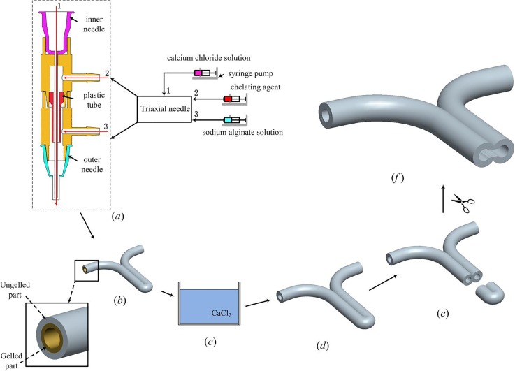
The triaxial nozzle used to fabricate hollow hydrogel fibers consists of two fluid dispensing tips and two different T-junction tubes. The cross sectional view of this nozzle and the feed of materials are demonstrated in Fig. 1(a).
FIG. 1.
Fabrication of ESBM. (a) Triaxial nozzle system for extruding cell-laden hollow hydrogel fibers. (b) Y-shape structure with the ungelled surface. (c) CaCl2 bath. (d) Completely cross-linked Y-shape structure. (e) and (f) Trimming with the microsurgery scissor.
In this triaxial nozzle, a 21 gauge (510 μm inner diameter (I.D.), 800 μm outer diameter (O.D.)) inner needle was inserted into the T-branch pipe, which has a smaller inner diameter, and a 16 gauge (1320 μm I.D.), 1600 μm O.D.) outer needle was equipped with the T-branch pipe, which has a bigger inner diameter. The cell-laden NaAlg was dispensed through the sheath section (inlet 3) of the triaxial nozzle by a syringe pump (RSP01-BDG, RISTRON, China; TJ-3A, LONGER, China), while the CaCl2 solution was dispensed through the core section (inlet 1) of the triaxial nozzle. The chelating agent was dispensed from inlet 2 when the triaxial nozzle clogged by calcium alginate, and the dispensing of cell-laden NaAlg should be ceased at this moment. The plastic tube was used to prevent the upflow of the cell-laden NaAlg.
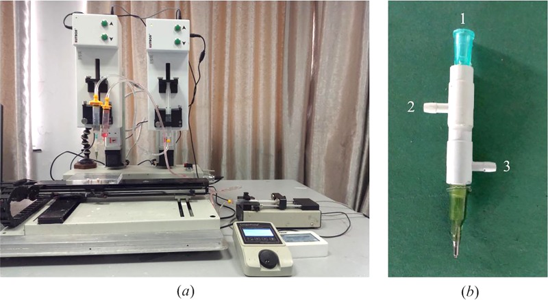
The experimental setup consists of a home-made 3D bioprinter (Rapid Manufacturing Engineering Center, Shanghai University, Shanghai, China) and three syringe pumps where biomaterials can be extruded and printed through the computer-controlled system (Fig. 2(a)). The enlarged view of the triaxial nozzle can be seen from Fig. 2(b). For fabrication of ESBM, as shown in Fig. 1, a Y-shape structure was printed at the room temperature (Fig. 1(b)). The travel speed of X and Y axes was both 10 mm/s. The overlap section was stick together due to the ungelled surface of the hollow fibers. Then, the Y-shape structure was placed into CaCl2 solution which has the same concentration as CaCl2 inside the triaxial nozzle for 1 h for full cross-linking (Fig. 1(c)). An aesthetic surgery scissor (Wenchuang Medical Instrument CO., LTD, Suqian, China) with a sharp cutting head was used to cut the head of the double channel section; two channels were observed in the Y-shape structure (Figs. 1(d) and 1(e)). Finally, the inside joint part of the double channel section was trimmed and turned the two channels into one, so as to form the main vessel part of the branched structures. The trimming depth of the joint part is 3–4 mm and the minimum width of the scissor's cutting head is only 0.1 mm. Thus, the scissor could be inserted into the double channel and an engineered structure with branched micro-channels was obtained smoothly (Fig. 1(f)).
FIG. 2.
3D bioprinter (a) and triaxial nozzle (b) used for the fabrication of ESBM.
C. Characterization
In order to observe the morphology of the ESBM, freshly prepared samples were maintained in a freeze-drier (LGJ-10D, Four-Ring Science Instrument Plant Beijing CO., Ltd, Beijing, China) at −30 °C and 12 Pa for 30 h until the branched structures became stiff. After that, the stiff structures were sputter coated with gold-palladium (E1010, Ion Sputter, Hitachi, Japan) before being observed using a scanning electron microscope (SEM, SU1510, Hitachi, Japan).
NaAlg and CaCl2 solutions at different concentrations could affect the thickness of the ungelled part on the outer surface of hollow fibers. Thus, the tensile strength of the double channel part was tested using a Zwick BZ2.5/TS1S material testing machine (Zwick/Roell Testing Machines Ltd, Germany) to confirm the optimal material concentration for making ESBM. Each end of the freshly prepared samples was rolled on a bolt and the two bolts were gripped with calipers on the testing machine. The distance between the two clamps was 50 mm. The tensile load was applied at a speed of 5 mm/min, at room temperature, until fracture occurred. The tensile strength can be derived from the ultimate strength of the samples. Five groups were tested, with six samples per group.
D. Perfusion test
The perfusion study was conducted with the branched structure to test the connectivity of the inner channel of the Y-shape structure. The perfusion of ESBM was tested via a customized perfusion method. A stainless steel needle and an injection syringe were used to inject cell culture medium into the branched structure and then placed the cell-laden branched structure into PBS.
E. Cell preparation
Mouse fibroblasts from Zhongqiaoxinzhou Biotech CO., Ltd., Shanghai, China, were routinely cultured in DMEM culture medium with 10% (v/v) fetal bovine serum, 100 U/ml of penicillin, and 100 μg/ml streptomycin (Invitrogen). The cells were maintained in an incubator at 37 °C in 5% CO2 in a humid atmosphere. Culture media were replaced every 2 days, and passage 3 cells were used for printing. Cells were trypsinized by 0.25% Trypsin-EDTA (Life Technologies, NY) and detached from cell culture dishes and then collected by centrifugation. Cells were mixed with the NaAlg solution (5% w/v in DMEM-based media) immediately after harvesting and kept at room temperature before the cell experiment. The cell density used in this study was 3 × 10⁶ cells/ml. The cell-laden samples were statically cultured for further research, with the medium changed every day in a CO2 incubator.
F. Viability analysis
Live-Dead Cell Staining Kit (Biovision, Inc., San Francisco, CA) was used to assess the cell viability of the encapsulated fibroblasts. Live cells were stained by a cell-permeable green fluorescent dye Live-Dye™ while the cell non-permeable red fluorescent dye propidium iodide (PI) was used to stain dead cells. These two fluorescent dyes were mixed with staining buffer before staining. After incubating the cell-laden branched structures with the assay at 37 °C for 15 min, the solutions were removed and the stained branched structures were washed three times with PBS and observed under a laser scanning confocal microscope (Olympus FluoViewTM FV1000, Olympus Corporation, Tokyo, Japan) with red and green fluorescence filters on day 0, 3, and 6. ImageJ was used for the automated counting of red- and green-stained fibroblasts, and percentages of viable cells were calculated according to the numbers it counted. The branched sections of the fabricated constructs were used for the calculations of cell viability and the calculations were done on a horizontal cross-section of the constructs.
G. Statistical analysis
Statistical analysis was performed using OriginPro 9 software. Tensile strength and cell viability data were statistically analyzed by one-way Analysis of Variance (ANOVA) followed by Tukey Test to determine which populations were significantly different; statistical significance was accepted when P < 0.05. The results listed here are shown as mean ± standard deviation (SD).
III. RESULTS AND DISCUSSION
A. Fabrication
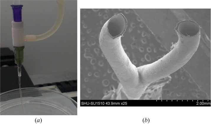
The triaxial nozzle successfully generated a coaxial flow of cell-laden NaAlg and CaCl2, and the hollow hydrogel fibers could also be extruded rapidly (Fig. 3(a)). CaCl2 solution infused through the inner needle and cell-laden NaAlg formed a sheath flow around the CaCl2 flow. Fabrication was performed with cell-laden NaAlg solution at a dispensing rate of 0.4 ml min−1 based on our early experiments, and CaCl2 solution was also dispensed at 0.4 ml min−1 for obtaining ungelled outer surface of hollow fibers. Hollow fibers were widely used to fabricate engineered scaffolds for vascularization in tissue regeneration.1,23 Thus, the ungelled part on the outer surface of fibers is a crucial factor to bond adjacent fibers for printing three-dimensional scaffolds. The ungelled surface could be obtained by adjusting the concentration of NaAlg and CaCl2.24 Therefore, hollow fibers with the ungelled surface can be used in this study. For the fabrication of branched samples, the triaxial nozzle would be easily clogged due to the gelation after a sample was finished. Continuous fibers could not be obtained when the concentration of NaAlg was above 2.5%.25 Therefore, the chelating agent could be dispensed through the inlet 2 to dissolve the solid gel quickly when the blockage was formed. In this process, all the other pumps were ceased. Once the clogged gel was removed, extrusion and fabrication process could resume. In order to obtain the branched structures, the hollow fibers should be deposited in the 3D bioprinter according to a Y-shape path. The motion control programs were developed in-house using G-code commands based on the geometry of the designed Y-shape structure. Fig. 3(b) shows bifurcations of a fabricated Y-shape structure.
FIG. 3.
(a) Extrusion of hollow hydrogel fibers. (b) SEM image of the Y-shape structure.
B. Morphology of the branched structures
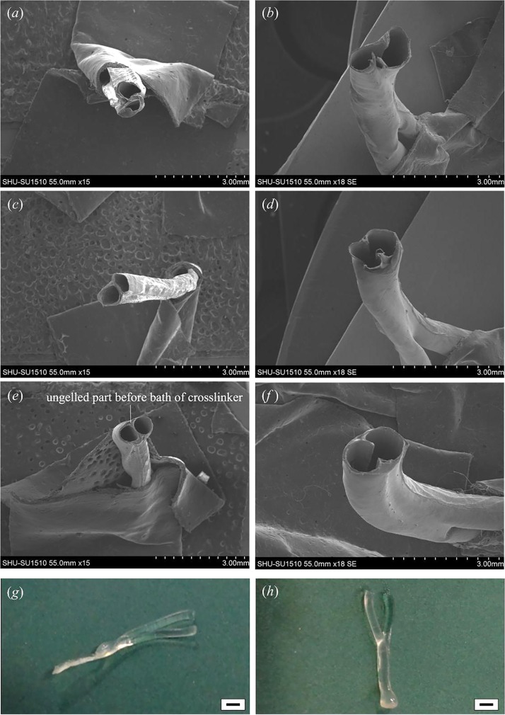
In order to verify the effect of the material concentration on ESBM, branched structures were fabricated at different concentrations, and the morphology of branched structures was observed with SEM. Based on early investigations of hollow hydrogel fibers, this paper noticed that the wall of hollow fibers was not thick enough to fabricate the branched structure when the concentration of NaAlg was below 3%. Thus, the initial concentration of NaAlg was set at 3%. The double channel parts of branched structures were also observed with SEM. The joint part was obscure and serious deformation occurred when the concentration of alginate was 3% (Fig. 4(a)). After trimming the double channel (Fig. 4(b)), the joint part could not maintain its original shape. An obvious leak appeared due to the low strength of the double channel part. For 4% NaAlg, the joint part showed a clear shape but a little deformation still existed in hollow fibers (Fig. 4(c)), and there was almost no ungelled part. Although the geometry was better than 3% NaAlg after trimming (Fig. 4(d)), the lack of shape integrity and strength could not be ignored. Fibers could hold their cylinder shape basically in the double channel part and more ungelled part was observed at 5% NaAlg (Figs. 4(e) and 4(f)). It is noticeable that the columnar hollow fibers in the double channel part kept well.
FIG. 4.
SEM images and samples of Y-shape ESBM fabricated at different concentrations of NaAlg when the CaCl2 concentration was fixed at 270 mM. (a) and (b) Double channel part of the Y-shape structure fabricated at 3% NaAlg and the channel after trimming. (c) and (d) Double channel part of the Y-shape structure fabricated at 4% NaAlg and the channel after trimming. (e) and (f) Double channel part of the Y-shape structure fabricated at 5% NaAlg and the channel after trimming. (g) Y-shape structure fabricated at 4% NaAlg. (h) Y-shape structure fabricated at 5% NaAlg. Scale bar in (g) and (h) is 2 mm.
The shape of ESBM can be seen from Figs. 4(g)–5(h). In Fig. 4(g), the double channel part was flat when the concentration of NaAlg was 4%, and it is obvious that the branched structure deformed. But the shape could keep when 5% NaAlg was used, as shown in Fig. 4(h). Therefore, 4% NaAlg and 270 mM CaCl2 could not be chosen as the optimal material concentration. In this experiment, two single fibers could not even integrate each other when 3% alginate was used with 270 mM CaCl2. Although the shape could keep at 5% and 6% alginate, a higher concentration of alginate could thicken the shell of hollow fibers and thus reduced the core space, which made it not convenient to trim the interlayer in the double channel part. Therefore, 5% alginate and 270 mM CaCl2 were confirmed to be the optimal material concentration. According to Fig. 3(b) and Fig. 4, the inner diameters of the single and double channels were 0.5 mm and 1 mm, respectively. Thus, the accuracy of the printed channel can be controlled in micro scale.
FIG. 5.
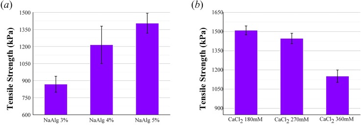
Tensile strength of the double channel part fabricated at different concentrations of NaAlg and CaCl2. (a) The NaAlg concentration levels set at 3%, 4%, and 5% with the CaCl2 concentration fixed at 3%. (b) The CaCl2 concentration levels set at 180 mM, 270 mM, and 360 mM with the NaAlg concentration fixed at 5%. The error bars indicate standard deviations (n = 6).
C. Effect of material concentration on mechanical properties of ungelled parts
Tensile strength of the double channel part for all samples is presented in Fig. 5. From the histogram, the mechanical property of samples fabricated at different concentrations of NaAlg and CaCl2 could be compared. Fig. 5(a) shows that the tensile strength increased significantly when the CaCl2 concentration was fixed at 270 mM and the cell-laden NaAlg concentration levels were set at 3%, 4%, and 5%. The tensile strength increased from 868 ± 70 kPa at 3% NaAlg, 1215 ± 164 kPa at 4% NaAlg, to 1405 ± 87 kPa at 5% NaAlg. The tensile strength decreased from 1510 ± 35 kPa at 180 mM CaCl2, 1447 ± 40 kPa at 270 mM CaCl2, to 1151 ± 48 kPa at 360 mM CaCl2 when the concentration of NaAlg was 5% (Fig. 5(b)).
The results showed that the tensile strength increased when the NaAlg concentration increased. In contrast, the tensile strength decreased when the CaCl2 concentration increased. The obvious change of these mechanical properties could be explained by the material properties of NaAlg. Sodium alginate is composed of blocks of β-D-mannuronic acid residues (MM-blocks), blocks of α-L-guluronic acid residues (GG-blocks), and blocks with alternating M and G residues (MG-blocks).26,27 Due to the blocks in NaAlg, more interactions between polymer chains occurred when the NaAlg concentration increased. Moreover, the gelation process occurred by binding carboxylic groups on G-blocks with divalent calcium ions in CaCl2 solution.28 When the CaCl2 concentration was fixed and NaAlg concentration increased, the content of NaAlg that could be cross-linked by calcium ions was invariable and the ungelled part on the outer surface of hollow hydrogel fibers increased. After cross-linking in the CaCl2 bath, the ungelled part would be stronger when the NaAlg concentration increased. Therefore, the tensile strength increased as the NaAlg concentration increased. As for the other group, the concentration of NaAlg was fixed and the CaCl2 concentration increased, tensile strength of samples fabricated at 270 mM CaCl2 was only 60 kPa smaller than the samples fabricated at 180 mM CaCl2. But another group decreased significantly. This is because the diffusion rate increased as the crosslinker concentration decreased and the exchange between Ca2+ in the crosslinker and Na+ ions of G units of alginate decreased.29 It made the gelation rate decreased. Thus, the tensile strength reduced when the concentration of CaCl2 solution increased. Although the maximum tensile strength was obtained at 5% NaAlg and 180 mM CaCl2, higher concentration of alginate would make the core lumen too narrow and it was not convenient to trim the double channel to a single channel. Moreover, the tensile strength obtained at 5% NaAlg and 270 mM in this study is really close to some native vasculature, such as the abdominal aorta (1.47 MPa) and coronary artery (1.30 MPa).30 Thus, we considered that the optimal parameters should be 5% NaAlg and 270 mM CaCl2.
D. Perfusion study
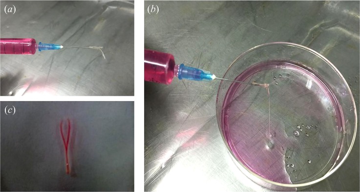
The perfusion test of ESBM (5% NaAlg, 270 mM CaCl2) was conducted using a syringe filled with cell culture medium (Fig. 6(a)). Two jets were obtained from the bifurcations of the branched structure (Fig. 6(b) (Multimedia view)). After placing the branched structure filled with cell culture medium into PBS, the bifurcations of the cell culture medium inside the branched structure were obvious (Fig. 6(c)). Thus, this proved that the inner channel of the branched structure was connected. Not only the Y-shape structure could be fabricated via this method but also structures with complex geometries. A one-to-three structure was fabricated successfully and PBS could be injected from the one-to-three channel smoothly (supplementary material, Fig. S1).
FIG. 6.
E. Viability analysis of encapsulated fibroblasts
Cells were distributed in NaAlg solution evenly before printing and were successfully encapsulated into hollow fibers during the fabrication process. The viability of fibroblasts was evaluated.
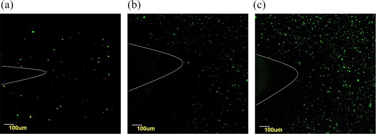
Fig. 7(a) shows a confocal microscopic image of viable fibroblasts on day 0. Observation of the live fibroblasts stained with green confirmed a distribution of cells in the double channel part. Due to the limitation of the amplification factor, the whole branched structure could not be observed, and only part of the Y-shape could be seen. The white curves in Fig. 7 were labeled to indicate the Y-shape structure. On day 3, although a few cells were stained with propidium iodide (red), most of the cells were still viable (Fig. 7(b)). After 6 days, the amount of cells increased, and only a few dead cells were observed (Fig. 7(c)). Cross sectional images of the encapsulated cells surrounding the lumen can be seen from Fig. S2 (supplementary material). The encapsulated fibroblasts distributed uniformly. And the wall thickness of the tested samples was approximately 150 μm.
FIG. 7.
Laser confocal images of viability staining. Fibroblasts labeled with Live-Dye and propidium iodide after encapsulation in the Y-shape structures. Live and dead cells were fluorescent green and fluorescent red, respectively. (a) and (b) Only a few dead cells are observed on day 0 and day 3. And (c) the amount of fibroblasts increased apparent on day 6.
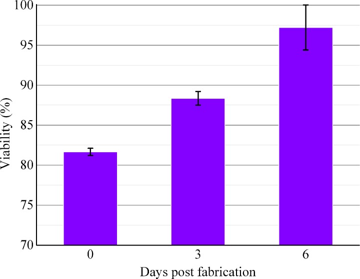
Image J analysis revealed that initial cell viability was around 81.67 ± 0.45% after encapsulation within the Y-shape structure. During in vitro culture, cell viability rose to 88.36 ± 0.86% on day 3 and kept increasing until day 6 (97.21 ± 2.81%) (Fig. 8). Primarily due to the shear stress between cells and nozzle during the extrusion process,29 cell viability was lower than 90% after printing. Besides, the high viscosity of alginate may also cause damage to cells because of the high shear forces to mix the alginate solution31,32 and the nutrients and oxygen could not be transported into cells in the center of fibers wall timely during the initial cross-linking period. Fibroblasts encapsulated in fibers had good proliferation activities, after culturing the branched structures at 37 °C for 3 and 6 days, and the cell viability increased and exceeded 95% finally. These results demonstrated that ESBM and the fabrication process were nontoxic.
FIG. 8.
Time course of fibroblasts' viability. Cell viability was analyzed using Image J. The error bars indicate standard deviations (n = 3).
IV. CONCLUSION
This paper presents a novel method for bio-fabricating ESBM, which shows potential to fabricate complex tissues of living organs in the near future.
The results indicate that it is useful and feasible to use hollow hydrogel fibers to fabricate branched micro-channel structures and realize vascularization in tissue regeneration in further research. Such a method has the following advantages: (1) the cross-linking hollow hydrogel fibers can be obtained easily using NaAlg and CaCl2; (2) materials used in this method are biodegradable, bio-compatible, and nontoxic, and no byproducts are produced after cross-linking; and (3) not only Y-shape branched structures can be made by this method but also the integrated part with multi-branch vessels can be produced by overlapping the hollow fibers.
Since sodium alginate and calcium chloride are widely used for fabricating micro-channels in tissue engineering, in this study the former was used as the cell-laden material and the latter was used as the cross-linker. These two materials were extruded by the syringe pump at a dispensing rate of 0.4 ml min−1 and printed as hollow hydrogel fibers. The chelating agent could be used in this experiment when the blockage was formed at fabrication intervals. The hollow hydrogel fibers fabricated by the triaxial nozzle were used to generate Y-shape or one-to-three structures, which, after properly trimming, could turn into ESBM. The gelation of the Y-shape structure was controlled by modulating the concentration of NaAlg and CaCl2. A mechanical property test of hollow fibers was conducted to confirm the optimal material concentration, and the optimal concentration of NaAlg and CaCl2 was proved to be 5% and 270 mM, respectively. Besides, the connection of the inner channel inside the branched structures was obvious, which could be observed after injecting cell culture media. The results also revealed that there was no blockage or swirling in the internal of the branched structures. Moreover, the application of fibroblasts demonstrated the non-toxic and biocompatibility of the cross-linking and fabrication process. Thus, this method can be used as a practical platform for the fabrication of micro-channels for vascularization.
In this study, trimming was used to convert the double channel or triple channel to one. But for constructs with more bifurcations, other method should be put forward to solve this problem. Instead, a single hollow fiber with a bigger inner diameter can be made to enclose the multichannel, using NaAlg to fill the gap between the outer surface of the multichannel and the inner surface of the bigger hollow fiber. Finally, CaCl2 was used to crosslink the filled NaAlg to integrate the entire structure. Maybe this method can be investigated in our further research for fabricating more complex structures.
SUPPLEMENTARY MATERIAL
See supplementary material for the one-to-three structure and cross sectional image of the encapsulated cells surrounding the lumen.
ACKNOWLEDGMENTS
The authors appreciate the funding support from the National Natural Science Foundations of China (Grant Nos. 51375292 and 51475281) and The National Science Fund for Young Scholars (Grant No. 51105239).
References
- 1. Zhang Y., Yu Y., Chen H., and Ozbolat I. T., Biofabrication (2), 25004 (2013). 10.1088/1758-5082/5/2/025004 [DOI] [PMC free article] [PubMed] [Google Scholar]
- 2. Dolati F., Yu Y., Zhang Y., De Jesus A. M., Sander E. A., and Ozbolat I. T., Nanotechnology (14), 145101 (2014). 10.1088/0957-4484/25/14/145101 [DOI] [PMC free article] [PubMed] [Google Scholar]
- 3. Park K., J. Controlled Release , 79 (2014). 10.1016/j.jconrel.2014.05.007 [DOI] [PubMed] [Google Scholar]
- 4. Jain R. K., Au P., Tam J., Duda D. G., and Fukumura D., Nat. Biotechnol. (7), 821–823 (2005). 10.1038/nbt0705-821 [DOI] [PubMed] [Google Scholar]
- 5. Hanjaya-Putra D., Shen Y. I., Wilson A., Fox-Talbot K., Khetan S., Burdick J. A., Steenbergen C., and Gerecht S., Stem Cells Transl. Med. (4), 297–306 (2013). 10.5966/sctm.2012-0111 [DOI] [PMC free article] [PubMed] [Google Scholar]
- 6. Guillemette M. D., Gauvin R., Perron C., Labbe R., Germain L., and Auger F. A., Tissue Eng., Part A (8), 2617–2626 (2010). 10.1089/ten.tea.2009.0612 [DOI] [PubMed] [Google Scholar]
- 7. Will J., Melcher R., Treul C., Travitzky N., Kneser U., Polykandriotis E., Horch R., and Greil P., J. Mater. Sci.: Mater. Med. (8), 2781–2790 (2008). 10.1007/s10856-007-3346-5 [DOI] [PubMed] [Google Scholar]
- 8. Nishiguchi A., Matsusaki M., Asano Y., Shimoda H., and Akashi M., Biomaterials (17), 4739–4748 (2014). 10.1016/j.biomaterials.2014.01.079 [DOI] [PubMed] [Google Scholar]
- 9. Zieber L., Or S., Ruvinov E., and Cohen S., Biofabrication (2), 24102 (2014). 10.1088/1758-5082/6/2/024102 [DOI] [PubMed] [Google Scholar]
- 10. Oh J., Kim K., Won S. W., Cha C., Gaharwar A. K., Selimovic S., Bae H., Lee K. H., Lee D. H., Lee S. H., and Khademhosseini A., Biomed. Microdevices (3), 465–472 (2013). 10.1007/s10544-013-9746-z [DOI] [PMC free article] [PubMed] [Google Scholar]
- 11. Nguyen L. H., Annabi N., Nikkhah M., Bae H., Binan L., Park S., Kang Y., Yang Y., and Khademhosseini A., Tissue Eng., Part B (5), 363–382 (2012). 10.1089/ten.teb.2012.0012 [DOI] [PMC free article] [PubMed] [Google Scholar]
- 12. Li Y., Liu Y., Jiang C., Li S., Liang G., and Hu Q., Soft Matter (8), 2392–2399 (2016). 10.1039/C5SM02733K [DOI] [PubMed] [Google Scholar]
- 13. Blaeser A., Duarte C. D., Weber M., Neuss S., Theek B., Fischer H., and Jahnen-Dechent W., BioRes. Open Access (5), 374–384 (2013). 10.1089/biores.2013.0031 [DOI] [PMC free article] [PubMed] [Google Scholar]
- 14. Miller J. S., Stevens K. R., Yang M. T., Baker B. M., Nguyen D. H., Cohen D. M., Toro E., Chen A. A., Galie P. A., Yu X., Chaturvedi R., Bhatia S. N., and Chen C. S., Nat. Mater. (9), 768–774 (2012). 10.1038/nmat3357 [DOI] [PMC free article] [PubMed] [Google Scholar]
- 15. He J., Zhu L., Liu Y., Li D., and Jin Z., J. Mater. Sci.: Mater. Med. (11), 2491–2500 (2014). 10.1007/s10856-014-5270-9 [DOI] [PubMed] [Google Scholar]
- 16. Li S., Liu Y., Liu L., and Hu Q., ACS Appl. Mater. Interfaces (38), 25096–25103 (2016). 10.1021/acsami.6b07725 [DOI] [PubMed] [Google Scholar]
- 17. Wu W., DeConinck A., and Lewis J. A., Adv. Mater. (24), H178–H183 (2011). 10.1002/adma.201004625 [DOI] [PubMed] [Google Scholar]
- 18. Huang Y., He K., and Wang X., Mater. Sci. Eng., C (6), 3220–3229 (2013). 10.1016/j.msec.2013.03.048 [DOI] [PubMed] [Google Scholar]
- 19. Jeffries E. M., Nakamura S., Lee K. W., Clampffer J., Ijima H., and Wang Y., Macromol. Biosci. (11), 1514–1520 (2014). 10.1002/mabi.201400306 [DOI] [PubMed] [Google Scholar]
- 20. Kim J., Yang K., Park H., Cho S., Han S., Shin Y., Chung S., and Lee J., Biotechnol. Bioprocess Eng. (3), 379–385 (2014). 10.1007/s12257-014-0021-9 [DOI] [Google Scholar]
- 21. Huang Z., Li X., Martins-Green M., and Liu Y., Biomed. Microdevices (5), 873–883 (2012). 10.1007/s10544-012-9667-2 [DOI] [PubMed] [Google Scholar]
- 22. Srigunapalan S., Lam C., Wheeler A. R., and Simmons C. A., Biomicrofluidics (1), 13409 (2011). 10.1063/1.3530598 [DOI] [PMC free article] [PubMed] [Google Scholar]
- 23. Gao Q., He Y., Fu J., Liu A., and Ma L., Biomaterials , 203–215 (2015). 10.1016/j.biomaterials.2015.05.031 [DOI] [PubMed] [Google Scholar]
- 24. Li Y., Liu Y., Li S., Liang G., Jiang C., and Hu Q., J. Biosci. Bioeng. (1), 111–116 (2016). 10.1016/j.jbiosc.2015.04.020 [DOI] [PubMed] [Google Scholar]
- 25. Cuadros T. R., Skurtys O., and Aguilera J. M., Carbohydr. Polym. (4), 1198–1206 (2012). 10.1016/j.carbpol.2012.03.094 [DOI] [PubMed] [Google Scholar]
- 26. Pereira R., Carvalho A., Vaz D. C., Gil M. H., Mendes A., and Bartolo P., Int. J. Biol. Macromol. , 221–230 (2013). 10.1016/j.ijbiomac.2012.09.031 [DOI] [PubMed] [Google Scholar]
- 27. Blandino A., Macias M., and Cantero D., J. Biosci. Bioeng. (6), 686–689 (1999). 10.1016/S1389-1723(00)87103-0 [DOI] [PubMed] [Google Scholar]
- 28. Li S., Liu Y., Li Y., Zhang Y., and Hu Q., Chem. Eng. Process. , 98–104 (2015). 10.1016/j.cep.2015.05.018 [DOI] [Google Scholar]
- 29. Zhang Y., Yu Y., Akkouch A., Dababneh A., Dolati F., and Ozbolat I. T., Biomater. Sci. (1), 134–143 (2015). 10.1039/C4BM00234B [DOI] [PMC free article] [PubMed] [Google Scholar]
- 30. Liu Y., Jiang C., Li S., and Hu Q., J. Mech. Behav. Biomed. Mater. , 12–25 (2016). 10.1016/j.jmbbm.2016.01.002 [DOI] [PubMed] [Google Scholar]
- 31. Kong H. J., Smith M. K., and Mooney D. J., Biomaterials (22), 4023–4029 (2003). 10.1016/S0142-9612(03)00295-3 [DOI] [PubMed] [Google Scholar]
- 32. Mardikar S. H. and Niranjan K., Biotechnol. Bioeng. (6), 697–704 (2000). [DOI] [PubMed] [Google Scholar]
Associated Data
This section collects any data citations, data availability statements, or supplementary materials included in this article.
Supplementary Materials
See supplementary material for the one-to-three structure and cross sectional image of the encapsulated cells surrounding the lumen.


