Abstract
Neural stem and progenitor cells (NPCs) generate processes that extend from the cell body in a dynamic manner. The NPC nucleus migrates along these processes with patterns believed to be tightly coupled to mechanisms of cell cycle regulation and cell fate determination. Here, we describe a new segmentation and tracking approach that allows NPC processes and nuclei to be reliably tracked across multiple rounds of cell division in phase-contrast microscopy images. Results are presented for mouse adult and embryonic NPCs from hundreds of clones, or lineage trees, containing tens of thousands of cells and millions of segmentations. New visualization approaches allow the NPC nuclear and process features to be effectively visualized for an entire clone. Significant differences in process and nuclear dynamics were found among type A and type C adult NPCs, and also between embryonic NPCs cultured from the anterior and posterior cerebral cortex.
Keywords: Neural stem cells, neural progenitor cells, stem cell processes, segmentation, tracking, lineaging, stem cell process dynamics, in-terkinetic nuclear migration
1 Introduction
Neural progenitor cells (NPCs) play a key role in the generation and maintenance of the nervous system. NPCs are proliferative, undergoing mitosis to generate daughter cells that are genetic copies of the parent. As this process repeats, a family tree, or clone of related cells develops. NPCs are also migratory, with cells moving as needed to form and maintain the functionally, spatially and morphologically distinct components of the nervous system.
Individual NPCs exhibit a complex cellular morphology, with rapidly forming and changing cellular processes or protrusions [1]. These NPC processes may be used to attach to different regional structures such as the apical or basal surface of the neuroepithelium during development [2], and may also be used to explore the environment. During the non-mitotic, or interkinetic portion of the cell cycle, NPC nuclei undergo distinct motion along the processes. This interkinetic nuclear migration (INM) has been observed in a wide variety of vertebrate cell types [3], and has been associated with the cell fate, or type of daughter cells that will be produced post-mitosis [4]. The relationship between INM and mechanisms controlling cell cycle and mitosis is an important open question [5, 6].
Fluorescence microscopy is most commonly used to visualize INM. Because INM generally involves the spatial patterning or organization of a 3-D structure such as the cortex or retina, 3-D fluorescence microscopy, either confocal or multi-photon, is a way to observe not only the INM, but also the resulting divisions and tissue formation. Fluorescence microscopy allows for images to be captured with distinct nuclear and cytoplasmic markers, making the analysis of INM easier for both manual and computational approaches. However, fluorescence imaging of NPCs places a limit on the duration of the imaging experiment because of the increased photo-toxicity. Long-term observation of proliferating NPCs at a temporal frequency sufficient to establish accurate tracking of cells requires the use of transmitted light microscopy [7, 8].
Using phase-contrast microscopy to image live NPCs can capture multiple rounds of cell division over a period of 5-7 days or even longer without the photo-toxic effects of fluorescence. This time duration allows mouse cells to complete as many as 8 or even 10 rounds of cell divisions. In vitro phase contrast imaging is able to capture both the NPC nucleus, or cell body, as well as the processes. The quantification of INM from phase microscopy is more challenging compared to fluorescence imaging. The processes appear and disappear at a high temporal frequency, sometimes over a period of minutes making it difficult to integrate temporal information into the process segmentation. The process intensities vary only slightly from the background, and generally do not exhibit the phase contrast halo artifact that makes it possible to more reliably segment the cell nuclear region. Any clutter in the image sequence can be hard to differentiate from cell processes, with dead cells or other detritus appearing virtually identical to actual processes. Another challenge is the quantity of image data involved in a typical experiment. Stem cell populations often exhibit heterogeneous behaviors, so experiments examining behaviors for clones of cells can require the analysis of hundreds of clones, tens of thousands of cells and millions of individual cell segmentations. Adding process dynamics to such an experiment makes analysis by hand impossible - automated techniques are required.
Analyzing NPC process dynamics from time-lapse microscopy image sequences requires the cell body and processes to be segmented in each frame. The segmentation results are associated temporally by a tracking algorithm. Lineaging identifies mitotic events and establishes parent-daughter relationships. Together, the tracking and lineaging results establish the lineage tree showing the temporal and mitotic relationships among all cells in the clone. Here we present a new technique for segmenting and tracking NPC processes in time-lapse phase contrast microscopy. Our approach first uses an existing open-source software tool known as LEVER (for Lineage Editing and Validation) to segment, track and lineage the cells [7–11]. The LEVER analysis segments and tracks cells throughout the image sequence and is the basis for the subsequent segmentation and tracking of the NPC processes. The phase contrast LEVER segmentation [12] captures the cell soma, and the centroid of this is used as the nuclear location. LEVER can optionally integrate fluorescence markers for identifying the nucleus or process boundaries, but these are not required.
Once the LEVER analysis is complete, each image is thresholded to identify the foreground pixels that may belong to processes. Morphological processing on this threshold image is used to remove any background clutter in the images such as dead cells or detritus. Each of the process foreground pixels are then assigned to the LEVER segmentation result that is closest in the sense of minimizing the geodesic distance, or the distance in traversing only foreground process pixels to the LEVER nuclear segmentation results. Once the process pixels have been assigned to LEVER cell tracks, the process bounding box is computed, and the projection of the nuclear location onto the principal axis of the bounding box is taken. This provides the location of the cell in every image frame, and also the location of the nucleus relative to the processes, the key features for characterizing both cellular and nuclear motion.
Figure 1 illustrates the process segmentation and analysis steps. Starting with the LEVER segmentation and tracking results (panel A), the image is next adaptively thresholded to identify possible process pixels, shown in red (B). Process pixels are assigned to the nearest segmentation using a geodesic distance (C). Finally, the process bounding box is established, and the nuclear location is projected onto the process principal axis, shown as a white dot (D).
Fig. 1. Segmentation and tracking of adult neural progenitor cell (NPC) processes.
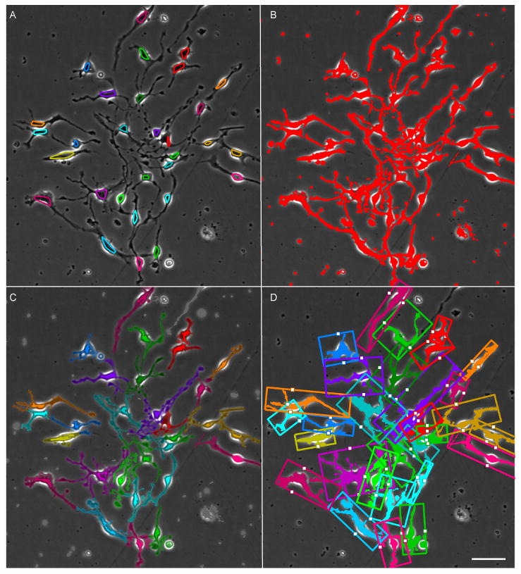
Results are shown for a single image from an 1100 frame time-lapse sequence, with convex hulls showing cell segmentation, colored by tracking assignment (A). A thresholding step identifies pixels that may belong to processes (B). A geodesic distance transform on the thresholded image is used to assign each process pixel to the nearest connected cell segmentation, with unassigned pixels in gray (C). Nuclear location and migration are established by projecting the nucelar centroid onto the principal axis of the bounding box of each cells processes, shown as the white dot (D). Scale bar indicates 50 μm.
2 Related Literature
Examining Figure 1, it can be observed that NPC process segmentation appears similar to the problem of neuron tracing, or neurite segmentation. Neuron tracing is an extremely well studied problem, including in phase contrast images [13]. A broad overview of the neuron tracing problem is given by Meijering [14]. Despite the superficial similarity between neurite segmentation and NPC process segmentation, the two applications are actually very different. Unlike neurons, NPCs are highly motile. The morphology of the cell body and of the processes changes dramatically over short periods of time. Also unlike neurons, NPCs are also proliferative, dividing to produce new cells. Finally, NPCs are more adherant compared to neurons, with cells frequently in close contact. For 2-D in vitro imaging, cells may also crawl on top of each other, causing significant overlap. Separating these touching cells is one of the principle challenges in working with NPC image sequence data.
The first automated computer algorithm for NPC segmentation, tracking and lineaging in phase contrast images was described by Al Kofahi, et al. [15]. More advanced tracking approaches for phase contrast images were descibed by Li et al. [16, 17]. For fluorescency microscopy images, Amat et al. describe an approach used with light-sheet microscopy images [18]. The CellProfiler program also has support for lineage analysis with track editing [19]. Winter et al. developed a tracking approach called Multitemporal Associate Tracking (MAT) that was designed specifically for objects that split and merge [20, 21]. The open-source LEVER program combined the MAT tracking algorithm with an online user-based validation [8]. LEVER works with 2-D+time phase contrast images, 5-D (3-D+multichannel+time) [11] and also with mixed phase and fluoresence microscopy images [9, 10]. LEVER uses an inference approach to incorporating human-provided corrections to the segmentation and tracking results. LEVER also uses contextual information about the cell populations obtained from the lineage tree to reduce the error rates of the automated analysis algorithms by more than 80% [7]. The LEVER program is used here to generate the cell segmentation, tracking and lineaging results.
3 Results
Two different experimental questions involving adult and embryonic mouse NPCs are addressed in this paper. First, differences in process dynamics are compared between type C and type A adult NPCs, two distinct sub-populations of adult NPCs. The second dataset that was analyzed consisted of embryonic NPCs cultured at E12.5 (12.5 days post-fertilization) from either the anterior or the posterior regions of the cerebral cortex. This dataset was previously used to study differences between anterior and posterior NPCs [7], and has been further analyzed here with process segmentation and tracking. The results of the automated segmentation, tracking and lineaging algorithms have been fully validated by human observers using the LEVER program [8]. This validation corrects any errors in the tracking or lineaging results. Validation of the segmentation by the human observer establishes that every cell has a segmentation result in every image frame. Validation of individual pixels assigned to each cell segmentation is detailed in Section 4. All of the automated image analysis results, including lineaging, tracking, nuclear and process segmentation, can be viewed interactively together with the image data using the CloneView program [7] as described in Section 5.
3.1 Type A and type C adult NPCs
The adult NPC dataset contains movies from four different imaging experiments. The data consists of 142 NPC clones, with a total of 1,350 cells or tracks and 361,867 individual cell segmentations. A total of 48 movies were processed. At the end of each experiment, cells were stained using immunohistochemistry to identify the cell types including type C and type A NPCs.
Figure 2 shows NPC process segmentation for a clone of cells that produces both type A and type C NPCs. The LEVER segmentation results are shown with different colors to indicate track IDs (A). Process pixels (half-tone) are assigned to the closest cell segmentation (solid-tone pixels) using a geodesic distance (B). Process pixels colored in gray could not be assigned to any cell track. Bounding boxes for the process pixels are colored according to cell fate commitment, with type A committed NPCs in red and type C committed NPCs in blue (C). Cell fate is established for each cell at the end of the experiment by fixing and staining the cells. Fate commitment is then applied to the tree retrospectively. A cell is considered committed to a fate iff all cells in the subtree rooted at the given cell are of the same fate. The lineage tree is colored by the generation of fate commitment, with subsequent generations having a darker hue. The lineage tree also shows process area (green line) and soma area (yellow line), each normalized per-clone, plotted next to each cell. Showing features on the lineage tree in this manner is a new and effective way to visualize nuclear and process dynamics for an entire clone.
Fig. 2. Segmentation, tracking and lineage results with cell fate commitment and soma and process areas for type A and type C NPCs.
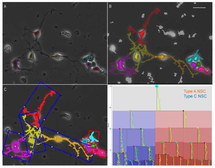
Single image from 1100 frame sequence (A) with cell segmentation and tracking results obtained from the LEVER program (B). Process segmentation and tracking result, with cell pixels shown in solid-tone and process pixels in half-tone (C). Bounding boxes are colored by cell fate commitment, with NPCs producing only type A NPCs in red and NPCs that produce only type C NPCs in blue. Lineage tree colored by fate commitment, with color hue darkening for each mitotic generation and soma and process areas ploted next to each cell cycle line. Process area for each cell is plotted in green normalized to the maximum process area per clone. Soma area for each cell is shown in yellow. Area values are normalized to the largest value on the clone. Scale bar indicates 25 μm.
Figure 3 shows summary statistics for fate-committed type A and C NPCs. Type C cells have significantly larger soma area (p = 10−46) and larger process area (p = 10−62) compared to type A cells. Type C cells exhibit lower nuclear velocity measured along the normalized process principal axis (p = 10−20). Type C cells can also be seen to exhibit different patterns of motion compared to type A cells, with a higher entropy of nuclear migration (p = 10−5). This means that the type C cells are more uniformly distributed along the process principal axis as compared to the type A cells.
Fig. 3. Summary statistics for type A and type C adult neural progenitor cells.
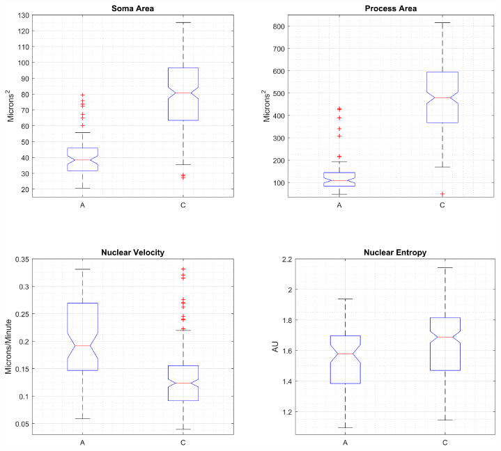
Box plots show median value as red line, blue box extents indicate the 25th-75th percentile of the data, data beyond whiskers are outliers. Notches indicate 95% confidence interval for the median. Type C cells have larger soma and processes, lower nuclear migration velocity and have increased entropy of nuclear location compared to type A cells.
3.2 Anterior and posterior cerebral cortex embryonic NPCs
The embryonic NPC dataset consists of 129 movies imaged in 3 different experiments. A total of 160 clones were analyzed, with 10,644 cells and 1,585,104 segmentations. The same analysis approach as used for adult NPCs was applied to the embyronic NPC data. Embryonic NPC clones are generally larger compared to adult clones. Figure 4 shows an example of the process segmentation and tracking results for an embryonic NPC clone. This clone contains 331 cells or tracks, and 30,229 individual cell segmentations. Starting with an unprocessed image frame (A), the LEVER segmentation and tracking results (B) are shown as the convex hulls of the cell pixels colored by track ID. The process pixels are shown segmented and tracked, colored by track assignment and with process pixels blended and cell pixels colored at full saturation (C). The process bounding box is shown in (D), with the projection of the nuclear centroid onto the process principal axis shown as a white dot. The feature used for analyzing nuclear location and velocity is the position of the nuclear centroid along this principal process axis, with the extents of the process axis normalized per frame to [-1,1].
Fig. 4. Cell and process segmentation and tracking with lineage tree for embryonic neural progenitor cell clone.
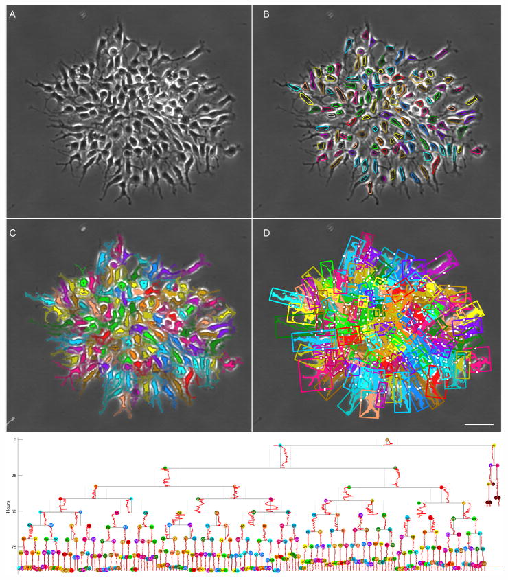
One image from an 1100 frame sequence (A), with LEVER segmentation and tracking results shown as convex hulls colored by track ID (B). After thresholding, processes are assigned to a cell track as indicated by the color (C), with solid tone for the cell segmentation, half tone for the process pixels and unassigned process pixels shown in gray. The centroid of the cell nucleus is projected onto the principal axis of the bounding box enclosing each cell and its processes, shown as a white dot (D). A new rendering combines conventional lineage information with the nuclear location feature (bottom), with the location of the nucleus for each cell along the normalized principal axis of the process bounding box plotted alongside the cell cycle indicator on the tree. Scale bar indicates 50 μm.
The lineage tree from Figure 4 also renders the time sequence of normalized nuclear location for each cell. For cell tracks that occur later in the movie, that lineage tree becomes very difficult to read as the spacing between cells on the lineage becomes quite tight. Figure 5 shows an alternative rendering for the lineage tree based on a radial tranform of cell relationships. The radius in this case corresponds to time, and angular orientation is used to position daughter cells below their parent. This alternative rendering for the lineage tree makes better use of the available space, making it easier to visualize the process features throughout the cell cycle.
Fig. 5. Radial rendering of the lineage tree with process dynamics.
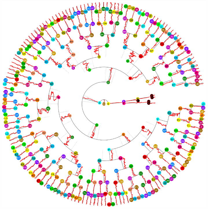
A new visualization for the lineage from Fig. 4 is shown, with time represented by the radius and cells distributed rotationally. Nuclear location along the process principal axis, normalized to [-1,1] is plotted alongside the radial line representing each cell lifespan. This visualization allows features associated with the lineage tree to be more clearly rendered at the distal cells in larger trees.
A statistical summary of cell and process size, as well as nuclear migration features is shown in Figure 6. Posterior cells have larger soma (p = 10−43) and process (p = 10−10) areas as compared to anterior cells. Posterior cells also exhibit signficantly different patterns of motion, with lower nuclear velocity (p = 10−10) and nuclear migration entropy (p = 10−19).
Fig. 6. Summary statistics for anterior and posterior cerebral cortex neural progenitor cells.
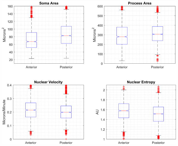
Box plots show median value as red line, blue box extents indicate the 25th-75th percentile of the data, data beyond whiskers are outliers. Notches indicate 95% confidence interval for the median. Anterior cells have smaller soma and process areas compared to posterior cells. Anterior cells also exhibit significantly different patterns in the motion of the nucleus along the processes, with increases to both nuclear velocity and to the entropy of the nuclear location.
One of the advantages of an analysis that follows the cells across multiple rounds of cell division is the ability to analyze cells based on what mitotic generation they were produced in. Figure 7 shows the nuclear and process area, as well as the nuclear velocity and the entropy of nuclear location all separated by generation. Generation 0 refers to the initially plated NPC, generation 1 are the cells created in the first division, etc. Note that anterior and posterior cells exhibit similar patterns of soma and process size, and nuclear migration dynamics (entropy and velocity) across generations. Interestingly, anterior NPCs show a later peak in process and soma area compared to posterior cells. This increase is driven by a small number of anterior clones that are larger, both in the cell and process size, compared even to the generally larger posterior cells.
Fig. 7. Summary statistics for anterior and posterior cerebral cortex neural progenitor cells by generation.
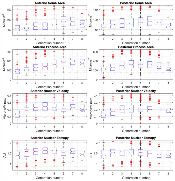
Cells are initially plated at generation zero, with each mitotic event producing a subsequent generation. Box plots show median value as red line, blue box extents indicate the 25th-75th percentile of the data, data beyond whiskers are outliers. Notches indicate 95% confidence interval for the median. Anterior cells and clones are generally smaller compared to posterior cells and clones. A small subset of anterior clones contributes to a late and significant increase in cell and process size.
4 Methods
The cell culture and image acquisition uses the same approaches as described previously [8, 7, 22]. Following image acquistion, the images are segmented, tracked and lineaged using the LEVER program. LEVER uses separate segmentation algorithms for the adult and embryonic cells. LEVER requires two parameters for each – maximum cell size and maximum velocity. The same parameters were applied to all of the embryonic data, and all the adult data.
Validation identifies and corrects errors in the automated algorithms[23]. The LEVER program is designed to make any errors in the segmentation, tracking and lineaging easy to identify and quick to correct [8]. Validation using the LEVER program verifies that tracking assignments and parent-daughter relationships are correct and that every cell has a segmentation in every image frame. Validation of the segmentation algorithms at the individual pixels was presented previously using the tracking algorithm and also using externally measured size differences between different cell populations based on flow cytometry [7].
Process segmentation and tracking consists of denoising, followed by thresholding and then assignment. Starting with a two dimensional image I, we invert the image and compute the morphological opening Iopen = max(min(I)) and then construct the denoised image from the white top-hat transform of I,
| (1) |
A disk shaped kernel with a radius of seven pixels is used for the opening. This removes variations in the phase contrast background across I. This Iwth has negative values at the phase contrast halo pixels – the bright artifacts surrounding thick regions associated with the cell body, and postive values interior to the cells and processes. Negative values are removed,
| (2) |
and the intensities are normalized to [0,1] forming the denoised image.
A dual-thresholding approach reduces the amount of background debris detected as process pixels (false positives). This uses the Otsu transform, TOtsu, weighted by [αL, αH] = [0.3, 0.6],
| (3) |
Any connected components with area smaller than ten pixels are removed from this image, and then a morphological reconstruction uses this first thresholded image to identify high-intensity regions in Idenoise,
| (4) |
Finally, the second threshold is applied to form the final thresholded image,
| (5) |
Following thresholding, each pixel is assigned the tracking ID as the nearest nuclear segmentation using a geodesic distance across BWfinal.
Once all foreground pixels from BWfinal have been assigned a tracking ID from the nearest segmentation result, the process bounding box is computed from the process pixel locations for track ID i, (x, y)i. The process pixels are centered, subtracting the mean value of the process pixel location,
| (6) |
The bounding box is computed using the singular value decomposition (SVD) of the spatial locations of the process pixels,
| (7) |
where the vectors V form an orthonormal basis that gives the principal axis directions for the process pixels [24]. The process pixels are projected into the V coordinate system, (x′, y′) = (x, y) ∗ V. The bounding box in the orthogonal space is computed and projected to the original space,
| (8) |
The projection of the nuclear centroid on the first coordinate in the V space, or the principal axis, is used as the nuclear location feature for velocity and entropy calculations. For entropy calculations, the principal axis is divided into ten bins.
Finally, all statistical tests were done with the non-parametric Wilcoxon Rank-Sum test for difference of medians [25].
5 Open Source Software and Data Availability
The LEVER program is available under the GNU Public License (GPL v2 or later). Details on obtaining source code or compiled executables are available from http://n2t.net/ark:/87918/d9rp4t. All of the image analysis results described here, together with the image data, are available interactively on the CloneView website: http://n2t.net/ark:/87918/d9wc73.
6 Conclusions
This paper describes new a new segmentation and tracking approach for NPC processes. One key challenge is to reject debris including dead cells while still capturing fine processes in cluttered images. New visualization techniques for the lineage tree enhance the ability to show nuclear and process dynamics for entire clones. Analyzing hundreds of clones found previously unknown significant differences in nuclear and process dynamics among functionally different populations of NPCs.
Acknowledgments
Portions of this research were supported by the NIH NINDS (R01NS076709), and by the NIH NIA (R01AG041861).
References
- 1.Ayala R, Shu T, Tsai L. Trekking across the brain: The journey of neuronal migration. Cell. 2007;128(1):29–43. doi: 10.1016/j.cell.2006.12.021. [DOI] [PubMed] [Google Scholar]
- 2.Strzyz JP, Lee OH, Sidhaye Jaydeep, Weber PI, Leung CL, Norden Caren. Interkinetic nuclear migration is centrosome independent and ensures apical cell division to maintain tissue integrity. Developmental Cell. 2015;32(2):203–219. doi: 10.1016/j.devcel.2014.12.001. [DOI] [PubMed] [Google Scholar]
- 3.Kosodo Y. Interkinetic nuclear migration: beyond a hallmark of neurogenesis. Cellular and Molecular Life Sciences. 2012;69(16):2727–2738. doi: 10.1007/s00018-012-0952-2. [DOI] [PMC free article] [PubMed] [Google Scholar]
- 4.Baye ML, Link AB. Interkinetic nuclear migration and the selection of neurogenic cell divisions during vertebrate retinogenesis. J Neurosci. 2007;27(38):10143–52. doi: 10.1523/JNEUROSCI.2754-07.2007. [DOI] [PMC free article] [PubMed] [Google Scholar]
- 5.Meyer JE, Ikmi Aissam, Gibson CM. Interkinetic nuclear migration is a broadly conserved feature of cell division in pseudostratified epithelia. Current Biology. 2011;21(6):485–491. doi: 10.1016/j.cub.2011.02.002. [DOI] [PubMed] [Google Scholar]
- 6.Spear CP, Erickson AC. Interkinetic nuclear migration: A mysterious process in search of a function. Development, Growth and Differentiation. 2012;54(3):306–316. doi: 10.1111/j.1440-169X.2012.01342.x. [DOI] [PMC free article] [PubMed] [Google Scholar]
- 7.Winter M, Liu M, Monteleone D, Melunis J, Hershberg U, Goderie S, Temple S, Cohen XR. Computational image analysis reveals intrinsic multigenera-tional differences between anterior and posterior cerebral cortex neural progenitor cells. Stem Cell Reports. 2015;5(4):609–620. doi: 10.1016/j.stemcr.2015.08.002. [DOI] [PMC free article] [PubMed] [Google Scholar]
- 8.Winter M, Wait E, Roysam B, Goderie S, Kokovay E, Temple S, Cohen AR. Vertebrate neural stem cell segmentation, tracking and lineaging with validation and editing. Nature Protocols. 2011;6(12):1942–52. doi: 10.1038/nprot.2011.422. [DOI] [PMC free article] [PubMed] [Google Scholar]
- 9.Mankowski WC, Winter MR, Wait E, Lodder M, Schumacher T, Naik SH, Cohen AR. Segmentation of occluded hematopoietic stem cells from tracking. Conf Proc IEEE Eng Med Biol Soc. 2014:5510–3. doi: 10.1109/EMBC.2014.6944874. [DOI] [PMC free article] [PubMed] [Google Scholar]
- 10.Mankowski WC, Konica G, Winter MR, Chen F, Maus C, Merkle R, Klingmüller U, Höfer T, Kan A, Heinzel S, Oostindie S, Hodgkin P, Cohen AR. Multi-modal segmentation for quantifying fluorescent cell cycle indicators throughout clonal development. Bioimage Informatics Conference. 2015 [Google Scholar]
- 11.Wait E, Winter M, Bjornsson C, Kokovay E, Wang Y, Goderie S, Temple S, Cohen AR. Visualization and correction of automated segmentation, tracking and lineaging from 5-d stem cell image sequences. BMC Bioinformatics. 2014;15(1):328. doi: 10.1186/1471-2105-15-328. [DOI] [PMC free article] [PubMed] [Google Scholar]
- 12.Cohen AR, Gomes F, Roysam B, Cayouette M. Computational prediction of neural progenitor cell fates. Nat Methods. 2010;7(3):213–218. doi: 10.1038/nmeth.1424. [DOI] [PubMed] [Google Scholar]
- 13.Al-Kofahi O, Radke JR, Roysam B, Banker G. Automated semantic analysis of changes in image sequences of neurons in culture. Biomedical Engineering, IEEE Transactions on. 2006;53(6):1109–1123. doi: 10.1109/TBME.2006.873565. [DOI] [PubMed] [Google Scholar]
- 14.Meijering E. Neuron tracing in perspective. Cytometry Part A. 2010;77A(7):693–704. doi: 10.1002/cyto.a.20895. [DOI] [PubMed] [Google Scholar]
- 15.Al-Kofahi O, Radke RJ, Goderie SK, Shen Q, Temple S, Roysam B. Automated cell lineage tracing: a high-throughput method to analyze cell proliferative behavior developed using mouse neural stem cells. Cell Cycle. 2006;5(3):327–335. doi: 10.4161/cc.5.3.2426. [DOI] [PubMed] [Google Scholar]
- 16.Li K, Miller DE, Weiss EL, Campbell GP, Kanade T. Online tracking of migrating and proliferating cells imaged with phase-contrast microscopy. Computer Vision and Pattern Recognition Workshop, 2006 Conference on. :65–65. [Google Scholar]
- 17.Li K, Miller ED, Chen M, Kanade T, Weiss LE, Campbell PG. Cell population tracking and lineage construction with spatiotemporal context. Medical Image Analysis. 2008;12(008):546–566. doi: 10.1016/j.media.2008.06.001. [DOI] [PMC free article] [PubMed] [Google Scholar]
- 18.Amat F, L W, P MD, McDole K, Wan Y, Branson K, Myers EW, Keller PJ. Fast, accurate reconstruction of cell lineages from large-scale fluorescence microscopy data. Nat Meth. 2014;11(9):951–958. doi: 10.1038/nmeth.3036. [DOI] [PubMed] [Google Scholar]
- 19.Bray M, Carpenter AE. Cellprofiler tracer: exploring and validating high-throughput, time-lapse microscopy image data. BMC Bioinformatics. 2015;16(1):1–7. doi: 10.1186/s12859-015-0759-x. [DOI] [PMC free article] [PubMed] [Google Scholar]
- 20.Winter RM, Fang C, Banker G, Roysam B, Cohen AR. Axonal transport analysis using multitemporal association tracking. Int J Comput Biol Drug Des. 2012;5(1):35–48. doi: 10.1504/IJCBDD.2012.045950. [DOI] [PMC free article] [PubMed] [Google Scholar]
- 21.Chenouard N, Smal I, Chaumont dF, Maska M, Sbalzarini FI, Gong Y, Cardinale J, Carthel C, Coraluppi S, Winter M, Cohen AR, Godinez JW, Rohr K, Kalaidzidis Y, Liang L, Duncan J, Shen H, Xu Y, Magnusson EK, Jalden J, Blau MH, Paul-Gilloteaux P, Roudot P, Kervrann C, Waharte F, Tinevez YJ, Shorte LS, Willemse J, Celler K, Wezel vPG, Dan WH, Tsai SY, Solorzano dOC, Olivo-Marin CJ, Meijering E. Objective comparison of particle tracking methods. Nat Methods. 2014;11(3):281–9. doi: 10.1038/nmeth.2808. [DOI] [PMC free article] [PubMed] [Google Scholar]
- 22.Kokovay E, Wang Y, Kusek G, Wurster R, Lederman P, Lowry N, Shen Q, Temple S. Vcam1 is essential to maintain the structure of the svz niche and acts as an environmental sensor to regulate svz lineage progression. Cell Stem Cell. 2012;11(2):220–230. doi: 10.1016/j.stem.2012.06.016. [DOI] [PubMed] [Google Scholar]
- 23.Cohen AR, Bjornsson C, Temple S, Banker G, Roysam B. Automatic summarization of changes in biological image sequences using algorithmic information theory. IEEE Trans Pattern Anal Mach Intell. 2009;31(8):1386–1403. doi: 10.1109/TPAMI.2008.162. [DOI] [PubMed] [Google Scholar]
- 24.Theodoridis S, Koutroumbas K. Pattern recognition. 4. Academic Press; San Diego, CA: 2009. [Google Scholar]
- 25.Bain LJ, Engelhardt M. Introduction to probability and mathematical statistics. Duxbury: 1992. [Google Scholar]


