Abstract
Multiplexing many SiPMs to a single readout channel is an attractive option to reduce the readout complexity of high performance time of flight (TOF) PET systems. However, the additional dark counts and shaping from each SiPM cause significant baseline fluctuations in the output waveform, degrading timing measurements using a leading edge threshold. This work proposes the use of a simple analog filtering network to reduce the baseline fluctuations in highly multiplexed SiPM readouts. With 16 SiPMs multiplexed, the FWHM coincident timing resolution for single 3mm × 3mm × 20mm LYSO crystals was improved from 401±4 ps without filtering to 248±5 ps with filtering. With 4 SiPMs multiplexed, using an array of 3mm × 3mm × 20mm LFS crystals the mean time resolution was improved from 436±6 ps to 249±2 ps. Position information was acquired with a novel binary positioning network. All experiments were performed at room temperature with no active temperature regulation. These results show a promising technique for the construction of high performance multiplexed TOF PET readout systems using analog leading edge timing pickoff.
1. Introduction
The signal to noise ratio of positron emission tomography (PET) images can be significantly improved using time of flight (TOF) with precise coincidence timing resolution (Budinger et al. 1983). Silicon photomultipliers (SiPM) are a promising visible light sensor for TOF PET systems. SiPMs are arrays of avalanche photodiode micro-pixels operated in Geiger mode (Buzhan et al. 2003) (Piatek et al. 2014) (Otte et al. 2005). SiPMs are ideal for fast timing measurements, but require a high number of high bandwidth analog readout channels, making scaling to a system level difficult.
To reduce the number of high bandwidth analog channels, SiPM timing channels can be multiplexed together. Multiplexing SiPMs together degrades the SiPM signal by adding dark counts. Each SiPM also has a capacitance. Additional capacitance added to the output channel by multiplexing SiPMs filters the output signal, increasing the decay constant of SiPM singals. Additional dark pulses with longer decay times contribute to fluctuations in the baseline of the SiPM signal, degrading the time resolution from simple leading edge threshold timing measurements. To reduce the effects of baseline fluctuations seen at high multiplexing ratios, a baseline correction algorithm that requires waveform sampling of the SiPM can be used (Vinke et al. 2009) (Bieniosek et al. 2016). However, a simple analog solution that does not require waveform sampling or digital signal processing on each SiPM waveform would be preferable to limit power consumption and data acquisition system complexity.
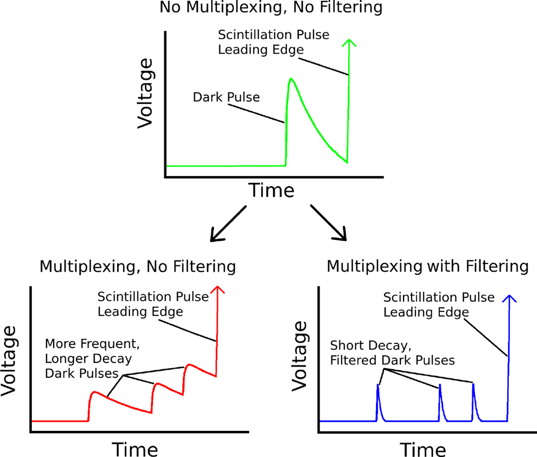
An analog filtering scheme could create very short SiPM dark count pulses that would have a lower probability of shifting the baseline for the measurement signals in the PET detector (see Figure 1). Previous works with non-multiplexed SiPMs have shown that filtering SiPM waveforms can indeed create much shorter SiPM micro-pixel waveforms while maintaining good timing performance (Gola et al. 2013) (Dolinsky et al. 2013). The aim of this work is to demonstrate that analog filtering techniques can be applied to multiplexed analog SiPM timing signals, allowing them to achieve fast timing performance without digital baseline correction algorithms or waveform sampling readout electronics. Such a scheme could greatly simplify the readout of multiplexed SiPM timing channels. In this work a simple passive analog filter is proposed, simulated and tested in single crystal and array measurements.
Figure 1.
Without multiplexing (top) dark pulses can affect the baseline of an SiPM readout signal before a scintillation pulse. Multiplexed SiPM readouts (bottom left) have more dark counts with longer decays that have a stronger effect on the signal baseline. Filtering multiplexed SiPM readouts (bottom right) can reduce the baseline fluctuations of multiplexed SiPM readouts.
2. Methods
2.1. Filtering Topology
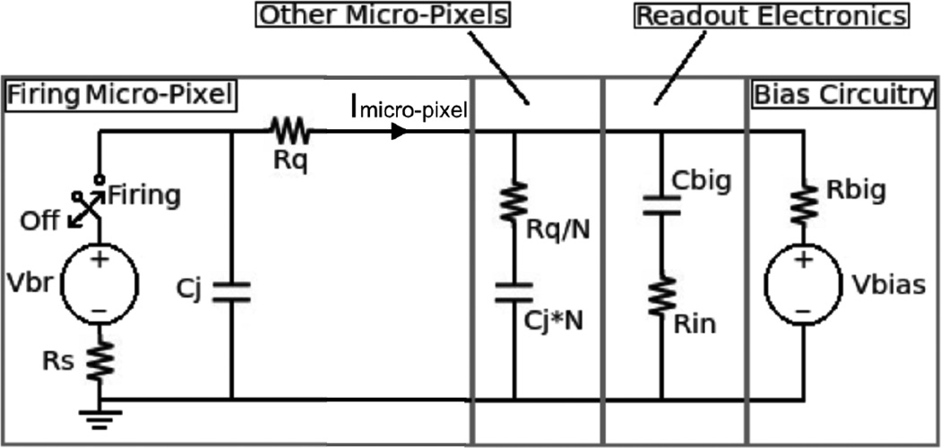
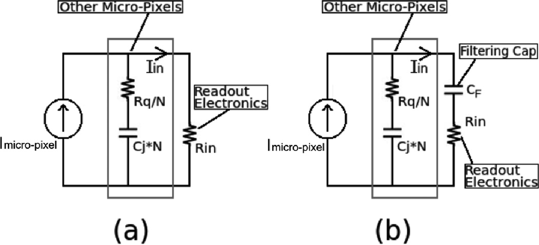
A filtering strategy was developed based on the circuit model of an SiPM micro-pixel seen in Figure 2 (Piatek et al. 2014). This model can be simplified at high frequencies as seen in Figure 3a given that the impedance to the bias voltage is high, the coupling impedance to the readout electronics is low and the SiPM quenching resistance is high compared to the impedance of the readout electronics. These assumptions all hold in typical conditions, such as those shown in Figure 2. Given this model the current through the readout electronics is given by a simple current divider:
| (1) |
To push the pole out to higher frequencies the large coupling capacitor Cbig in Figure 2 can be replaced with a smaller filtering capacitor (see Figure 3b). With this change, the contribution of the coupling capacitor at high frequencies can no longer be ignored and the transfer function now becomes:
| (2) |
Reducing the magnitude of the filtering capacitor should make the SiPM pulse decay faster similar to what is seen in Figure 1, as well as reduce the overall magnitude of the SiPM pulse.
Figure 2.
Circuit model of an SiPM micro-pixel is shown where Vbr is the breakdown voltage, Rs (IkΩ) is the depletion region resistance, Rq (150kΩ) is the quenching resistance, Cj (90 fF) is the junction capacitance, N (3584 per SiPM) is the number of connected micro-pixels, Cbig (100nF) and Rin (100Ω) model AC coupled output electronics, and Vbias (Vbr + 3.9V) and Rbig (2kΩ) model DC coupled bias circuitry.
Figure 3.
(a) Simplified high frequency SiPM micro-pixel model assuming Rq, Cbig and Rbig are large relative to other impedances in the model, (b) SiPM high frequency model with filtering capacitor.
2.2. Single Micro-Pixel Experiments
To confirm that the SiPM pulse is indeed shaped as predicted by Equation 2, simulations and measurements of single micro-pixel SiPM dark counts with different filtering capacitor values were performed. In Equation 2 each of the variables are known constants except for the current source, Imicro−pixel. Imicro−pixel was determined by measuring the dark count output waveforms of a single 3mm × 3mm Hamamatsu S12642-0404PA-50 SiPM. The dark counts were amplified with a Minicircuits ZX60-4016E+ 4GHz 20dB gain preamplifier (Minicircuits, Brooklyn, USA), and digitized with an Agilent 2.5 GHz 20GSa/s DSO90254A oscilloscope (Agilent, Santa Clara, USA). Many single micro-pixel dark count waveforms were averaged to determine the average micro-pixel pulse shape (Imeasured). Using the inverse of Equation 1, Imicro−pixel was calculated:
| (3) |
This waveform was then filtered using Equation 2 to simulate the output with different capacitor values from 100nF to 10pF. The simulations were compared to measurements of averaged micro-pixel waveforms with the different capacitor values to validate our model.
2.3. Single Crystal Timing Experiments
To find the optimal filtering capacitor for SiPM timing, coincidence timing experiments were performed while sweeping the filtering capacitor value, and the number of SiPMs multiplexed.Timing measurements of single 3mm × 3mm × 20mm lutetium-yttrium oxyorthosilicate (LYSO) crystals were made coupled to Hamamatsu S12642-0404PA-50 SiPMs biased at 3.9V above the breakdown voltage as seen in Figure 4. The timing channels were amplified with Minicircuits ZX60-4016E+ 4GHz preamplifiers, and digitized with an Agilent 2.5 GHz 20GSa/s DSO90254A oscilloscope. Energy channels were digitized directly with the scope. For small filtering capacitors the energy resolution of the module may be degraded. This can be rectified with a parallel low frequency energy channel (see Section 4 or (Bieniosek et al. 2015)). In this setup the number of SiPMs multiplexed was varied from 1 to 16 by simply connecting additional SiPMs in parallel, henceforth referred to as a 'short circuit' multiplexing configuration. Only one LYSO crystal was used, therefore each additional SiPM was not coupled to any crystal. In this way the effects of dark counts, noise, and shaping from multiplexed SiPMs are seen, independent of the effects of additional crystals or schemes to determine crystal position. The filtering capacitor value was swept from 100nF to 10pF for each number of multiplexed SiPMs.
Figure 4.
Circuit diagram with variable numbers of short circuit multiplexed (simply connected in parallel) SiPMs (left) and crystal setup (right) for single crystal multiplexing experiments.
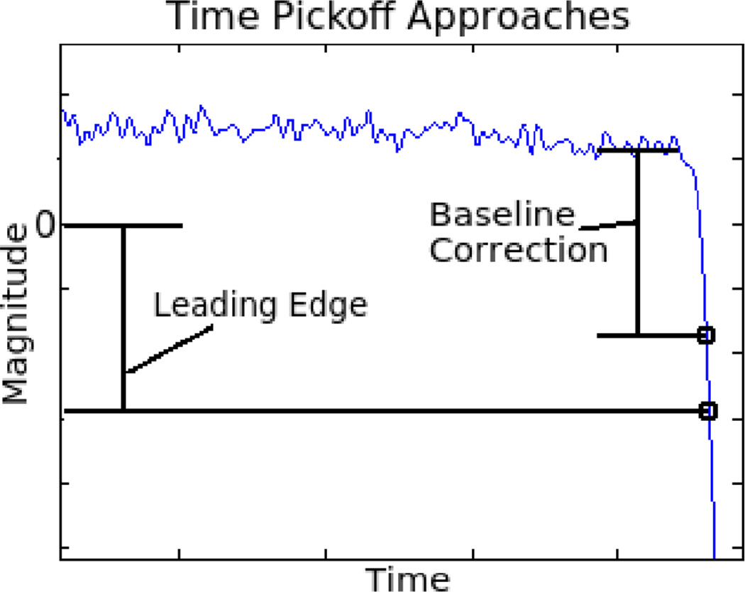
Time stamps were generated in two different ways, leading edge threshold without baseline correction, and leading edge threshold with baseline correction. Leading edge threshold without baseline correction is simply a measure of when a waveform crosses a threshold voltage. This is a simple timing system that is used in typical PET system designs. Leading edge threshold with baseline correction measures when the waveform crosses a voltage threshold relative to its baseline, which we defined to be the average voltage of the waveform for 500ps before the scintillation pulse (see Figure 5). Baseline correction was used to create a gold standard timing resolution that would be observed without baseline variations. However, this algorithm requires fast digitization of each scintillation waveform, which may be too resource intensive to implement on many PET systems. For all measurements the threshold voltages were swept to find the optimal threshold voltage in each timing measurement.
Figure 5.
To mitigate the effects of baseline fluctuations on time resolution, baseline corrected leading edge time pickoff can be used where the timing threshold is referenced to the signal baseline instead of 0V. This approach requires capture of a high quality digitized waveform for time pickoff. The analog method proposed in this paper does not require a digitized waveform. Instead, analog filtering is used to reduce baseline fluctuations.
2.4. Crystal Array Timing Experiments
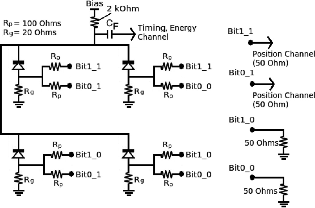
Finally, timing measurements were made with 2×2 arrays of 3mm × 3mm × 20mm lutetium fine silicate (LFS) crystals. The crystal arrays were coupled to a 2×2 array of Hamamatsu S12642-0404PA-50 SiPMs connected with a binary multiplexing network as seen in Figure 6. The 4 multiplexed SiPMs are read out by a single timing channel and 2 position channels. The binary multiplexing network gives each SiPM a binary code corresponding to its connections to two position channels. The magnitudes of the SiPM pulses seen on each position channel is unique for each SiPM. To produce a flood map events are simply placed on a two dimensional histogram, where the x coordinate corresponds to the magnitude of the first position channel (integrated for 60ns), and the y coordinate corresponds to the magnitude of the second position channel (integrated for 60ns). All SiPMs in the scheme see the same impedance, reducing distortion in the flood map.
Figure 6.
Circuit implementation of the binary multiplexing scheme. Each anode has a low impedance path to ground and two split channels. Codes that are ‘1’ are connected to output readouts, codes that are ‘0’ are connected to dummy 50Ω resistors
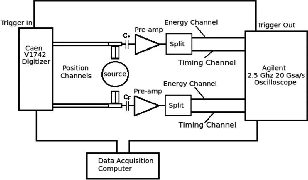
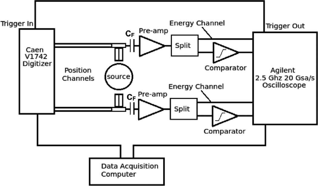
Timing channels were amplified by a Minicircuits ZX60-4016E+ 4GHz preamplifier (Minicircuits, Brooklyn, USA) and read out by an Agilent 2.5 GHz 20GSa/s DSO90254A oscilloscope (Agilent, Santa Clara, USA). Time stamps were generated according to the leading edge threshold with no additional signal processing steps. The leading edge thresholds were swept to find the optimal threshold voltage in each timing measurement. Position channels were read out with a CAEN V1742 digitizer, and position information was obtained from the integral of the position waveform (see Figure 7). Timing measurements were also made with timing pickoff performed by a discrete analog ADCMP572 comparator after pre-amplification (see Figure 8). All experiments were performed at room temperature with no active temperature regulation.
Figure 7.
Block diagram of crystal array timing experiments (without comparator). Each 2×2 array of SiPMs has 2 position channels digitized by a CAEN V1742 digitizer and a timing/energy channel digitized by a high speed oscilloscope.
Figure 8.
Block diagram of crystal array timing experiments (with comparator). Each 2×2 array of SiPMs has 2 position channels digitized by a CAEN V1742 digitizer and a timing/energy channel digitized by a high speed oscilloscope. In this setup a comparator performs the leading edge time pickoff of the scintillation signal before digitization.
3. Results
3.1. Single Micro-Pixels
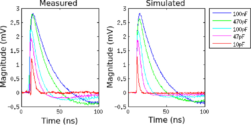
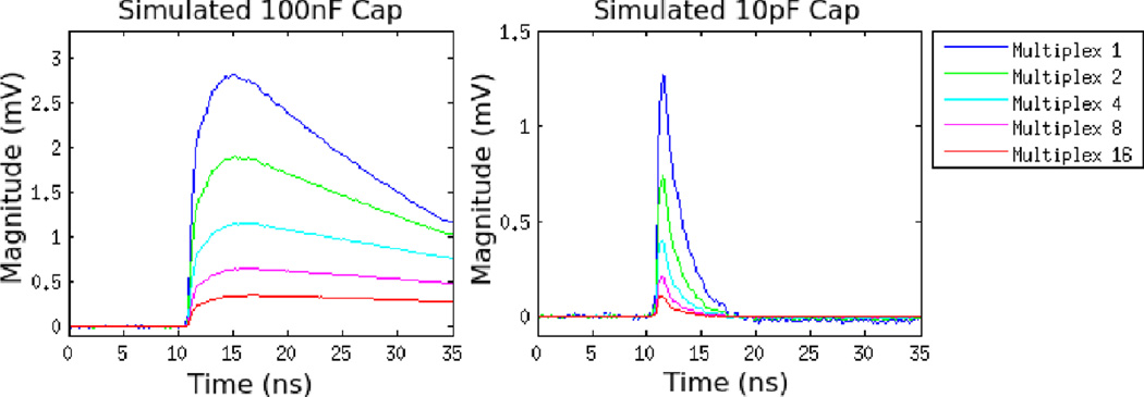
Simulated and measured single micro-pixel pulse shapes are seen in Figure 9. Both show that the use of a smaller filtering capacitor can drastically reduce the time for the SiPM signal to return to its original baseline to under 20ns. Pulse heights were also reduced by smaller filtering caps. The pulse heights of the simulations matched the measurement results to within 7% SiPM micro-pixel waveforms were also simulated with different multiplexing ratios as seen in Figure 10. As additional SiPMs are multiplexed, the magnitude of the single micro-pixel pulses is reduced. The reduction from 1 to 16 SiPMs is a factor of ~8 with a 100nF filtering capacitor and a factor of ~12 with a 10pF filtering capacitor.
Figure 9.
Average measured (left) and simulated (right) single micro-pixel waveforms from a single SiPM with the filtering capacitor swept from 100nF to 10pF
Figure 10.
Simulated single micro-pixel waveforms with multiplexing ratio varying from 1 to 16 in the setup described in Figure 4. Waveforms are shown with a 100nF filtering capacitor (left), and with a 10pF filtering capacitor (right).
3.2. Single Crystal Timing
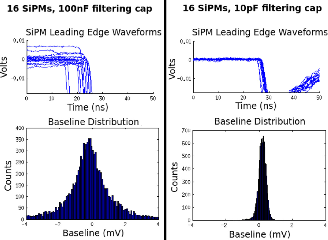
Filtering the SiPM waveform was successful in reducing the baseline variation as seen in Figure 11. A single SiPM with a 100nF filtering capacitor has a baseline standard deviation of 0.32mV. With 16 SiPMs multiplex the baseline standard deviation rises to 1.5mV. With a 10pF filtering capacitor, however, 16 SiPM baseline standard deviation falls to 0.24mV.
Figure 11.
Magnified leading edge waveforms from 511keV photo-peak events (top) and baseline distributions (bottom) for the timing channels of 16 SiPMs multiplexed with a 100nF filtering capacitor (left) and with a 10pF filtering capacitor (right).
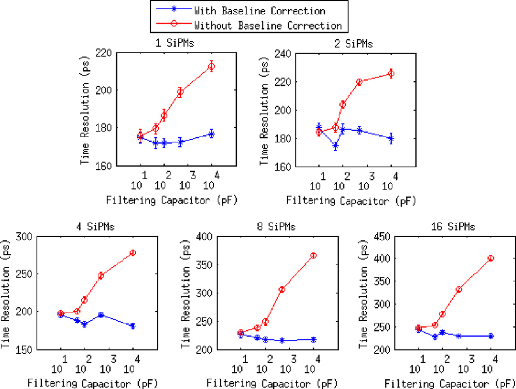
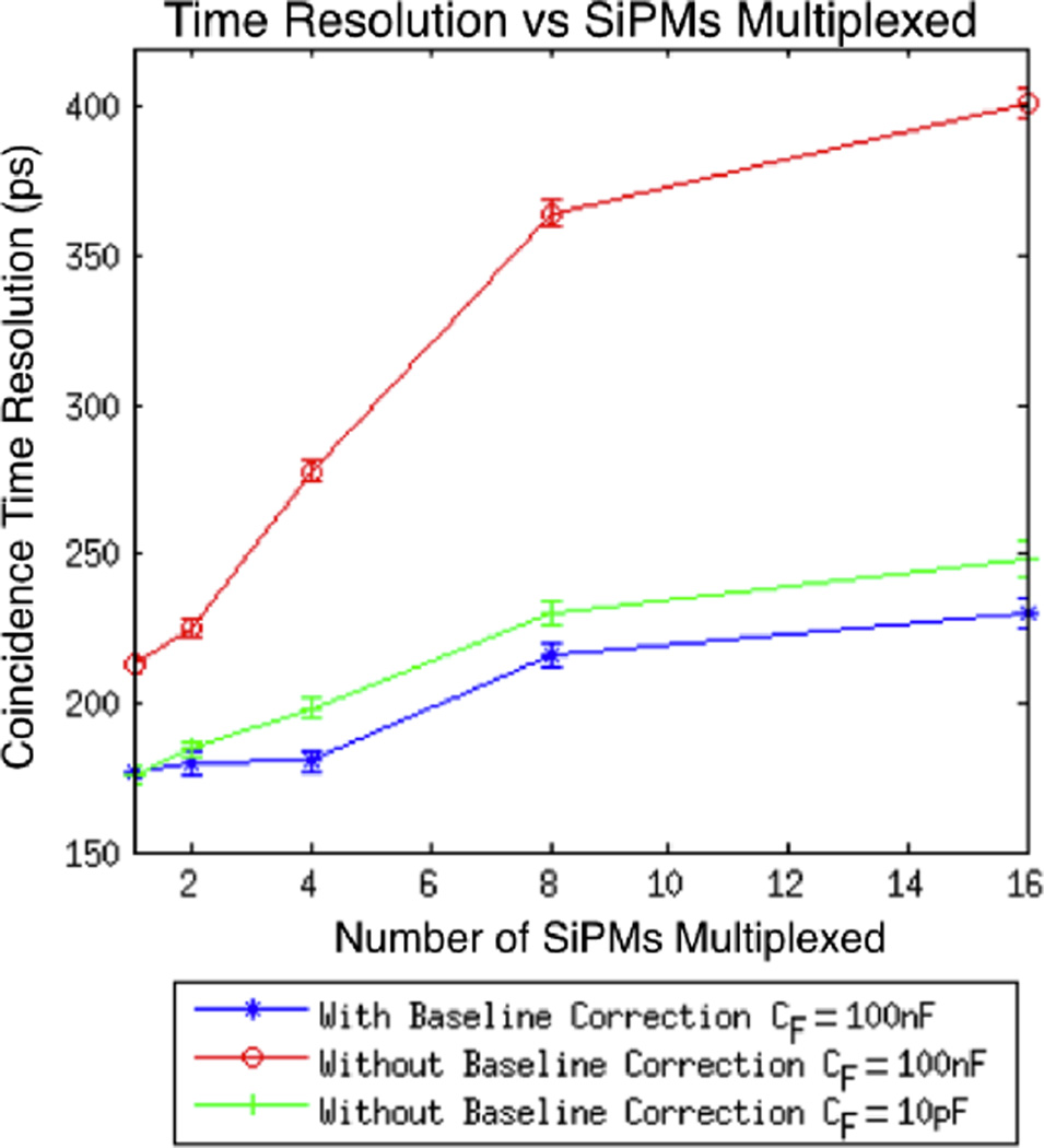
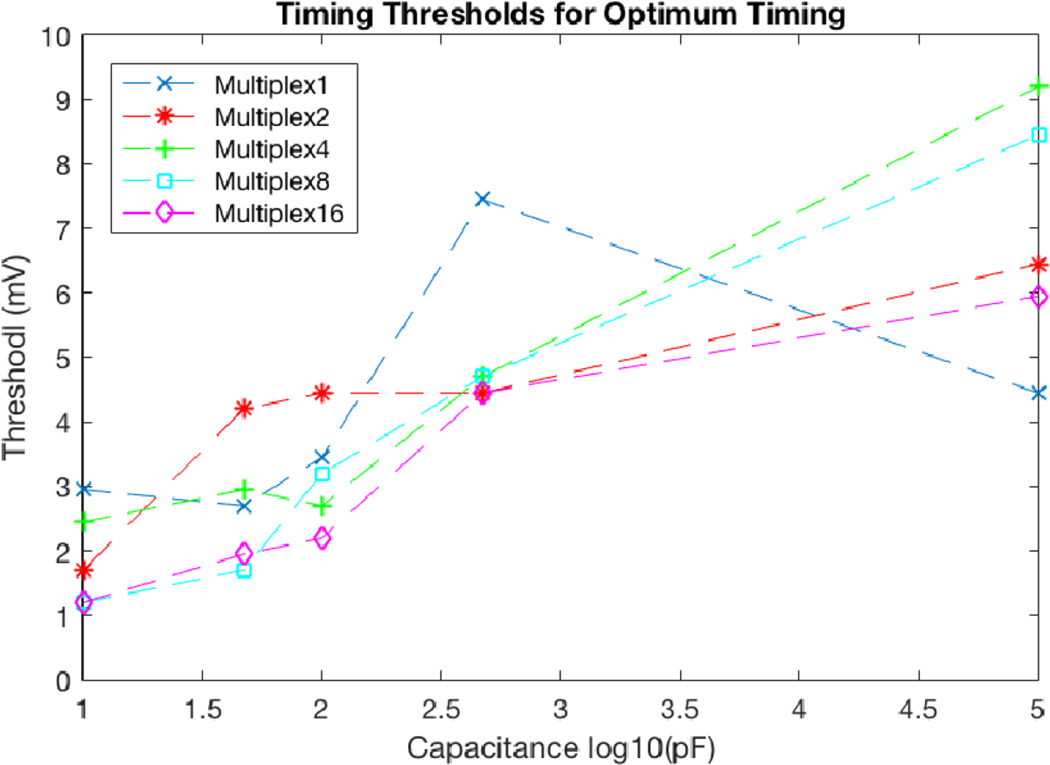
Results of short circuit multiplexing timing experiments with single 3mm × 3mm × 20mm LYSO crystals are shown in Figures 12 and 14. Smaller filtering capacitors improve time resolution without baseline correction down to 10pF, at which point baseline corrected and non-baseline corrected measurements have very similar timing resolutions. With 16 SiPMs multiplexed the FWHM coincident timing resolution was improved from 401 ± 4ps using a 100nF filtering capacitor to 248 ± 5ps using a 10pF filtering capacitor. All error bars are one sigma Gaussian fitting errors. The timing thresholds for optimum timing resolution are shown in Figure 13
Figure 12.
FWHM coincident timing resolutions of single 3mm × 3mm × 20mm LSYO crystals vs filtering capacitor value for 1, 2, 4, 8 and 16 SiPMs multiplexed.
Figure 14.
FWHM coincident timing resolutions of single 3mm × 3mm × 20mm LSYO crystals vs number of SiPMs multiplexed. Decreasing the filtering capacitor 10pF greatly reduces timing degradation without baseline correction.
Figure 13.
Optimum timing threshold levels for each point seen in Figure 12.
3.3. Crystal Array Timing
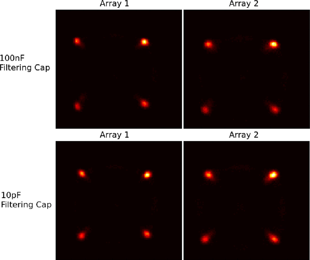
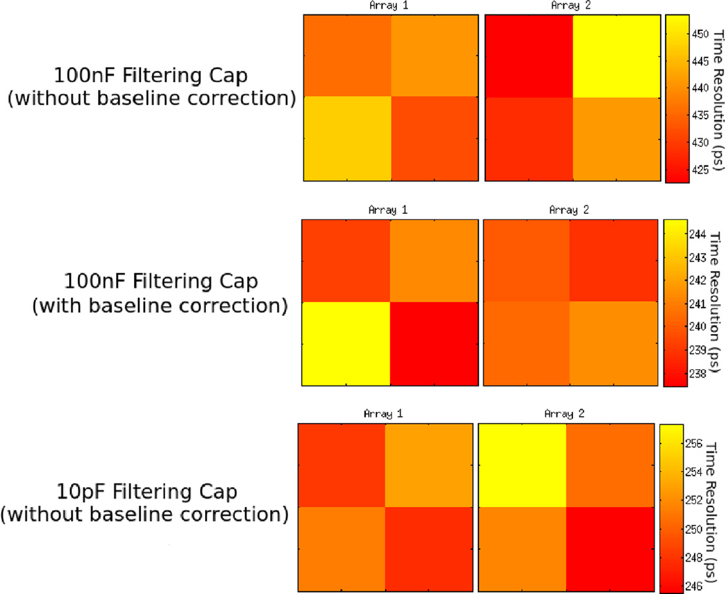
Coincident time resolution measurements were taken with two multiplexed 2×2 SiPM array coupled to 2×2 arrays of LFS crystals with a 100nF filtering capacitor and a 10pF filtering capacitor. With each of the filtering capacitors the crystals were well separated as seen in Figure 15. Average time resolution without baseline correction was 436 ± 6ps full width half maximum (FWHM). With baseline correction time resolution improved to 240 ± 2ps FWHM. Time resolutions for each individual crystal can be seen in Figure 16. With 10pF filtering capacitors average time resolution without baseline correction was 249 ± 2ps full width half maximum (FWHM). With the discrete ADCMP572 comparator time pickoff and 10pF filtering capacitors the time resolution was 247 ± 2ps FWHM. All error bars are one sigma Gaussian fitting errors.
Figure 15.
Flood map of the 2×2 arrays of multiplexed SiPMs coupled to 2×2 arrays of 3mm × 3mm × 20mm LFS crystals. The X and Y axes are the magnitudes of the position signal integrals. Four discrete clusters in each flood map show that each of the 4 LFS crystals in the array can be clearly identified.
Figure 16.
FWHM coincident time resolution for each crystal of two 2×2 arrays of 3mm × 3mm × 20mm LFS crystals coupled to 2×2 arrays of multiplexed SiPMs.
4. Discussion
The filtering topology used in this work was developed based on the simplified SiPM models seen in Figures 2 and 3. Simulations of single micro-pixel waveforms based on this model matched measurements as seen in Figure 9. This validates the use of the simplified SiPM model for filter development. SiPM filtering methods can be developed with a very simple and easily understood circuit model.
The filtering method achieved its goal of reducing baseline fluctuations. The simulations and measured single micro-pixel responses in Figures 9 and 10 show that the simple filtering technique reduces the time for the SiPM signal to return to its original baseline to under 20ns. Shorter dark counts lead to a more stable baseline as illustrated in Figure 1 and measured in Figure 11. However, the magnitude of the signal is also reduced by a factor of 2.3 using a 10pF filtering capacitor instead of a 100nF capacitor. This attenuation is in addition to a large attenuation due to multiplexing. Thus we would expect a trade off between a stable baseline from a very small filtering capacitor and a large signal magnitude from a large filtering capacitor.
Multiplexed timing resolution with analog filtering was first tested with a simple short circuit multiplexing scheme and a single LYSO crystal (see Figure 4). This scheme, while impractical for a PET system due to its lack of position information, shows the effects of the filtering with the minimum confounding factors. Timing resolution without baseline correction improves with smaller capacitors down to 10pF, where it is within 10% of the non-filtered baseline correction timing see Figures 12 and 14. While the time resolution with and without baseline correction are very similar using a 10pF filtering capacitor, the time resolution is still not as good as time resolution with baseline correction and a 100nF filtering capacitor. This degradation may be due to the smaller signal magnitude. Filtering capacitors smaller than 10pF would further attenuate the SiPM signal, likely degrading time resolution.
Figure 13 shows the threshold level for optimum timing resolution at each multiplexing and filtering level. There are several competing factors that determine the optimum timing threshold. As the single micro-pixel pulse gets smaller (due to multiplexing or filtering) the optimum timing threshold will fall to continue to trigger at the same photon level. However, as noise sources are added (due to multiplexing) the optimum threshold will rise to stay above the noise level. In general the timing thresholds are lower for heavily filtered waveforms, but do not have a strong trend due to multiplexing.
To show that this method can be implemented on a more practical system that has a crystal coupled to every SiPM, and position sensitivity, array timing measurements were made. An excellent average coincidence time resolution of 249 ± 2ps was measured, while maintaining a well separated flood map (see Figures 16 15). Timing pickoff was also performed with a discrete ADCMP572 comparator to make the readout electronics similar to a typical PET data acquisition system. The comparator timing measurements were within the measurement error from the waveform sampling oscilloscope data, showing that the strategy is practical for scaled PET systems.
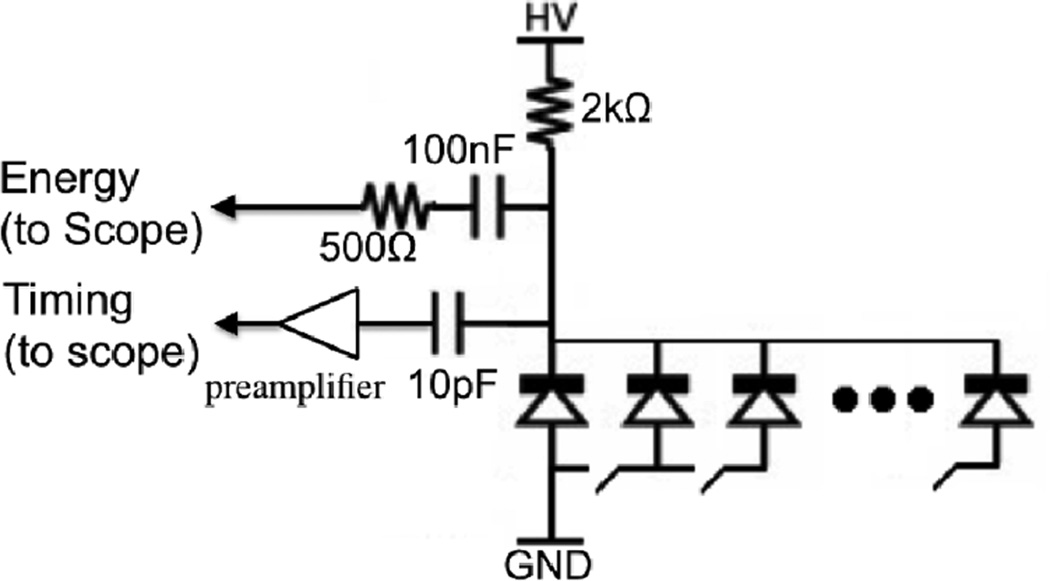
In addition to timing and position resolution PET detectors require energy resolution. Small filtering capacitors attenuate the SiPM signal and can degrade energy resolution, especially at high multiplexing ratios. To maintain good energy resolution a parallel energy channel with a large capacitance should be used as seen in Figure 17 and described in (Bieniosek et al. 2015). The energy channel has a resistor in series to maintain an impedance much higher than 50 Ohms. At high frequencies (where the filtering capacitor has a low impedance) the resistor will block the output signal, preventing the energy channel from affecting the timing channel. Lower frequency signals will be blocked by the filtering capacitor and be sensed by the energy readout.
Figure 17.
With a parallel high impedance energy channel, the lower frequency energy signal can be measured without affecting the high frequency timing signal.
The results shown in this work can be used to greatly simplify the readout of PET systems. Multiplexing is extremely important in TOF PET. While new TOF PET ASICs are making SiPM-based TOF PET systems possible (Choong et al. 2013) (Fischer et al. 2006) (Rolo et al. 2013), multiplexing will allow PET systems to use far fewer ASICs to reduce their power, cost, area and complexity. Alternatively more power hungry, higher performance ASICs can be used because fewer channels need to be read out.
5. Conclusions
Multiplexing SiPMs can greatly reduce the number of PET readout channels to make a simpler data acquisition system. The analog filtering technique characterized in this work shows significant time resolution improvements for multiplexed SiPM readout using a simple leading edge time stamp without digitization or further signal processing. This result was confirmed both on single crystals with short circuit multiplexing (connecting SiPMs in parallel), and arrays of crystals with position sensitive multiplexing. This approach could lead to the construction of high performance, highly multiplexed TOF PET readout systems that do not require waveform sampling or digital signal processing algorithms to correct for baseline fluctuations.
Acknowledgments
The authors would like to thank Zecotek Photonics Inc. for LFS crystal samples. This work was supported in part by NIH research grants R01EB011552 and R21EB014405, and NIH training grant F31CA171573.
References
- Bieniosek MF, Cates JW, Levin CS. Nuclear Science Symposium Conference Record (NSS/MIC), 20015 IEEE. IEEE; 2015. A light sharing, charge multiplexed time-of-flight depth-of-interaction pet detector; pp. M4D1–M4D4. [Google Scholar]
- Bieniosek MF, Cates JW, Levin CS. Achieving fast timing performance with multiplexed SiPMs. Physics in Medicine and Biology. 2016;61.7:2879. doi: 10.1088/0031-9155/61/7/2879. [DOI] [PubMed] [Google Scholar]
- Budinger TF. Time-of-flight positron emission tomography-status relative to conventional PET. J. Nucl. Med. 1983;24:73–78. [PubMed] [Google Scholar]
- Buzhan P, et al. Silicon photomultiplier and its possible applications. Nuclear Instruments and Methods in Physics Research Section A: Accelerators, Spectrometers, Detectors and Associated Equipment. 2003;504.1:48–52. [Google Scholar]
- Choong W-S, et al. High-performance electronics for time-of-flight PET systems. Journal of Instrumentation. 2013;8.01:T01006. doi: 10.1088/1748-0221/8/01/T01006. [DOI] [PMC free article] [PubMed] [Google Scholar]
- Fischer, Peter, et al. Nuclear Science Symposium Conference Record, 2006. IEEE. Vol. 4. IEEE; 2006. Multi-channel readout ASIC for TOF-PET. [Google Scholar]
- Gola A, Piemonte C, Tarolli A. Analog Circuit for Timing Measurements With Large Area SiPMs Coupled to LYSO Crystals. Nuclear Science, IEEE Transactions on. 2013 Apr;60(2):1296–1302. [Google Scholar]
- Dolinsky S, Geng Fu, Ivan A. Timing resolution performance comparison for fast and standard outputs of SensL SiPM; Nuclear Science Symposium and Medical Imaging Conference (NSS/MIC), 2013 IEEE; [Oct. 27 2013-Nov. 2 2013]. p. 1.p. 6. [Google Scholar]
- Otte AN, et al. A test of silicon photomultipliers as readout for PET. Nuclear Instruments and Methods in Physics Research Section A: Accelerators, Spectrometers, Detectors and Associated Equipment. 2005;545.3:705–715. [Google Scholar]
- Piatek SS. Physics and Operation of an MPPC. [Accessed: Jan. 20, 2015];Hamamatsu Tutorial. 2014 [Online] Available: http://www.hamamatsu.com/us/en/community/opticalsensors/tutorials/physicsofmppc/index.html. [Google Scholar]
- Rolo MD, et al. Journal of Instrumentation. Vol. 8.02. APA; 2013. TOFPET ASIC for PET applications; p. C02050. [Google Scholar]
- Vinke R, et al. Optimization of digital time pickoff methods for LaBr3-SiPM TOF-PET detectors; Nuclear Science Symposium Conference Record (NSS/MIC), 2009 IEEE; [Oct. 24 2009-Nov. 1 2009]. p. 2962.p. 2968. [Google Scholar]


