

Abstract
Objective
Individual carbon fiber microelectrodes can record unit activity in both acute and semi-chronic (∼1 month) implants. Additionally, new methods have been developed to insert a 16 channel array of carbon fiber microelectrodes. Before assessing the in vivo long-term viability of these arrays, accelerated soak tests were carried out to determine the most stable site coating material. Next, a multi-animal, multi-month, chronic implantation study was carried out with carbon fiber microelectrode arrays and silicon electrodes.
Approach
Carbon fibers were first functionalized with one of two different formulations of PEDOT and subjected to accelerated aging in a heated water bath. After determining the best PEDOT formula to use, carbon fiber arrays were chronically implanted in rat motor cortex. Some rodents were also implanted with a single silicon electrode, while others received both. At the end of the study a subset of animals were perfused and the brain tissue sliced. Tissue sections were stained for astrocytes, microglia, and neurons. The local reactive responses were assessed using qualitative and quantitative methods.
Main results
Electrophysiology recordings showed the carbon fibers detecting unit activity for at least 3 months with average amplitudes of ∼200 μV. Histology analysis showed the carbon fiber arrays with a minimal to non-existent glial scarring response with no adverse effects on neuronal density. Silicon electrodes showed large glial scarring that impacted neuronal counts.
Significance
This study has validated the use of carbon fiber microelectrode arrays as a chronic neural recording technology. These electrodes have demonstrated the ability to detect single units with high amplitude over 3 months, and show the potential to record for even longer periods. In addition, the minimal reactive response should hold stable indefinitely, as any response by the immune system may reach a steady state after 12 weeks.
Keywords: Flexible electrodes, Minimal injury, High density array, Neural electrodes
1. Introduction
Recording stable, low-noise, high-amplitude unit activity in the motor cortex is crucial for the long-term stability of any brain machine interface (BMI) system [1–9] and can be equally important in many neuroscience studies [10–13]. To accomplish this goal, a system of electrodes should ideally elicit little to no immune response, have the capacity to concurrently record from a large population of neurons to either access more information content or to better understand local population dynamics, and demonstrate the ability to chronically record neural activity.
The initial insertion of any electrode is a traumatic event to the local cellular network and vasculature and is greatly influenced by insertion speed [14,15], location [16], and technique [17,18]. If the electrode is removed soon after insertion, the local area will heal [19,20]. Permanent implantation of the electrode leads to the eventual formation of a localized glial scar comprised chiefly of astrocytes and microglia [20–32]. Accompanying the scar is a varying degree of neuronal cell death within the immediate vicinity of the electrode [20,21,25,30]. The persistence of the scar can be attributed to multiple factors including the continual release of inflammatory factors by the locally activated glial cells [27,28,33] and a breached blood brain barrier that cannot completely heal, therefore allowing the infiltration of pro-inflammatory cells and chemokines [19,34,35]. The impact that these chemokines have on the local environment has been shown through the use of genetic knockouts. The removal of monocyte chemoattractant protein 1 led to improved neuronal density [36] while caspase-1 knockout mice demonstrated significantly better recording quality as compared to wild type mice [37].
One way to mitigate the inflammatory response is through a reduced probe footprint. The reduction in probe size has been shown to reduce the mechanical strain on nearby neurons [37], lessen the long-term glial response, and improve the survival rates of the local neuronal population [38–40]. It should be noted that these studies demonstrating an improved tissue response made use of hard materials, such as silicon [39,40], and softer materials, such as SU-8 and parylene [38]. While an electrode's material properties may play an important role in bridging the mechanical mismatch between an implant and the brain, the previous studies on electrode dimensions point to probe size as being a more critical factor.
We have recently proposed a multi-electrode array design using carbon fibers as the basis for the recording electrode [41,42]. Carbon fiber electrodes are small (d = 6.8 μm), and with the addition of a parylene-c insulating coating (t = 800 nm), the overall diameter is only increased to 8.4 μm. In addition, this electrode material is extremely amenable to creating high density arrays and with a site coating of poly(3,4-ethylenedioxythiophene) (PEDOT) has been shown to record high quality unit activity [41,43,44].
This work evaluates the longevity of these arrays, by first testing two different formulations of the site coating material, PEDOT, using an accelerated aging test. Carbon fiber arrays functionalized with parylene-c and PEDOT were further evaluated by chronically implanting them into rat motor cortex. Additionally, some animals were implanted with a commercially available planar silicon electrode in the contralateral hemisphere's motor cortex. Impedance and electrophysiology recordings were taken on a regular basis and analyzed to demonstrate the carbon fiber's viability as a chronic electrode technology. Lastly, a subset of animals were perfused and stained to quantitatively analyze the glial response and neuronal density surrounding both electrode types.
2. Materials & Methods
2.1 Soak Test
2.1.1 Probe Assembly
Printed circuit boards (PCBs) for accelerated soak testing were first roughened in the non-trace and non-bond pad areas with a Dremel tool, to allow for better adherence of the final epoxy coating (figure 1(a)). Once roughened, eight individual carbon fibers (T-650/35 3K, Cytec Thornel, Woodland Park, NJ), with length of approximately 1 cm, were placed on the individual bond pads using conductive silver epoxy (H20E, Epoxy Technology, Billerica, MA) (figure 1(b)). The conductive epoxy was then oven cured using the manufacturer's recommended settings. The silver epoxy bond was then covered with insulating epoxy (353NDT, Epoxy Technology, Billerica, MA) and oven cured using the manufacturer's recommended settings (figure 1(c)).
Figure 1. Soak test probe assembly and setup.
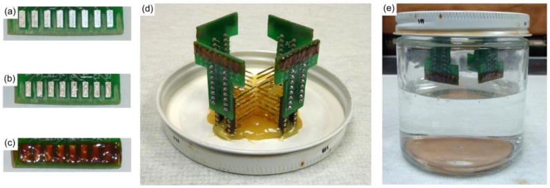
(a) Areas between and surrounding the bond pads have been roughened. (b) Silver epoxy on each bond pad for the carbon fibers. (c) Exposed bond pads with carbon fibers are covered with insulating epoxy. (d) Four PCBs with functionalized fibers are secured to the underside of the soak jar's lid. (e) Lids are secured to jars containing 1× PBS. Jars are then placed in a heated water bath.
Probes were then insulated with a conformal coating of parylene-c (t=800 nm) using a Parylene Deposition System 2010 (SCS Coatings, Indianapolis, IN). After insulation, the tips of each probe were cut to re-expose a bare carbon fiber site. At this site, one of two solutions was electrodeposited. The first was a solution of 0.01 M 3,4-ethylenedioxythiophene (483028, Sigma-Aldrich, St. Louis, MO):0.1 M sodium p-toluenesulfonate (152536, Sigma-Aldrich, St. Louis, MO). The second solution was composed of 0.01 M 3,4-ethylenedioxythiophene (483028, Sigma-Aldrich, St. Louis, MO):0.1 M polystyrene sulfonate (m.w. 70.000, 222271000, Acros, NJ). For each solution the electrodeposition was carried out by applying 100 pA/channel for 600 seconds to form a layer of poly(3,4-ethylenedioxythiophene):sodium p-toluenesulfonate (PEDOT:pTS) or poly(3,4-ethylenedioxythiophene):polystyrene sulfonate (PEDOT:PSS). All channels to be coated with a given solution were shorted together during the electrodeposition step and the current delivered was scaled accordingly.
2.1.2 Accelerated Soak Test Setup
Boards with parylene-c and PEDOT:pTS or PEDOT:PSS coated carbon fibers were mounted to the underside of a jar lid (figure 1(d)). The lids were then secured to jars that contained 1× phosphate buffered saline (PBS) solution (BP3994, Fisher, Waltham, MA) (figure 1(e)). The 1× PBS was at a level such that only the fibers were submerged and not the entire printed circuit board. The jars were then lowered into a water bath maintained at 60 °C. At each time point the fibers were removed from the heated 1× PBS and rinsed once with deionized water. Next, the fibers' impedances were recorded. Once recordings were complete the assembly was returned to the heated 1× PBS.
According to works by Green et al. [45] and Hukins et al. [46], equation (1) can be used to determine the aging time that the fibers have undergone:
| (1) |
Where t37 is the simulated aging time at 37 °C, tT is the amount of real time that the samples have been kept at the elevated temperature, T, and Q10 is an aging factor that is equal to 2, according to ASTM guidelines for polymer aging [47]. Calculating the simulated time for tT = 1 and T = 60 °C results in t37 = 4.92. This value of 4.92 is the acceleration factor and all real time measurements are scaled by this amount to obtain the simulated time.
2.1.3 Electrochemical Impedance Spectroscopy (EIS)
EIS measurements were taken with a PGSTAT12 Autolab (EcoChemie, Utrecht, Netherlands), controlled by vendor-supplied NOVA software. Measurements were obtained by applying a 10 mVRMS signal from 10 Hz to 31 kHz. Custom Matlab (Mathworks, Natick, MA) scripts were used to determine frequency specific impedance values. All reported values are mean ± standard error of the mean.
2.2 Chronic Electrode Implantation
2.2.1 Carbon Fiber Array Preparation
Carbon fiber arrays were fabricated as previously described [42]. Briefly, individual fibers were secured to bare traces (152.4 μm pitch) of a custom made PCB with silver epoxy that was then heat cured. This exposed contact was then coated with a heat cured insulating epoxy to protect the connection between the fiber and trace. Once fully assembled, all carbon fiber arrays for neural recordings were coated with an 800 nm thick insulating layer of parylene-c using a Parylene Deposition System 2010 (SCS Coatings, Indianapolis, IN). Probe tips also received a site coating of PEDOT:pTS with the same formula and deposition parameters used on the fibers that underwent soak testing. The final preparation step was a coating of poly(ethylene glycol) (PEG) as described in [42].
2.2.2 Surgery for Chronic Implantation of Carbon Fibers and Silicon Probes
Chronic implantation of carbon fiber arrays (figure 2(a)) and silicon probes (figure 2(b)) used adult male Long Evans rats (n=3 rats with only carbon fibers, 3 with both electrodes, and 2 with only silicon probes) weighing 300 – 350 g. Rats were first anesthetized using 5% isoflurane (v/v) for induction and then 1 – 3% isoflurane (v/v) for maintenance. The head was then shaved and triple swabbed using alternating applications of betadine and 70% ethanol. Ointment was applied to the eyes to keep them from drying during surgery. Once mounted in the stereotax, the shaved area was swabbed one more time with betadine and 70% ethanol. A subcutaneous injection of lidocaine (4 mg/mL) was given at the incision site at a maximum dosage of 4 mg lidocaine per 1 kg of body weight. After incision, the skin flaps were pulled away using hemostats and the skull surface cleaned. A burr bit (19008-07, Fine Science Tools, Foster City, CA) was used to drill seven holes around the periphery of the skull for seven bone screws (19010-00, Fine Science Tools, Foster City, CA). Next, 2 mm × 3 mm craniotomies were made over the left and right motor cortex using coordinates from a reference atlas [48]. Before resecting the dura, a layer of Kwik-Sil (World Precision Instruments, Sarasota, FL) was applied to the skull at the posterior, anterior, and leftmost sides.
Figure 2. Images of implanted electrodes.
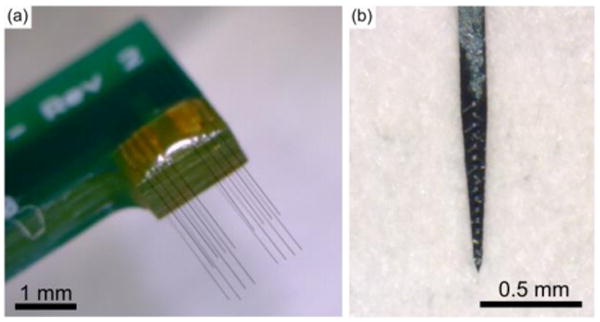
(a) Carbon fiber array used in implants. (b) Silicon probe, NeuroNexus A1×16-3mm-50-177-HZ16_21mm, with sixteen 177 μm2 iridium sites spaced 50 μm apart, used in implants.
Following the resection of the dura on the rightmost craniotomy, the PEG coated carbon fiber array was brought to the surface of the brain. The exposed fibers were implanted according to methods previously described [42]. The silicon probes (A1×16-3mm-50-177-HZ16_21mm, NeuroNexus Technologies, Ann Arbor, MI) were 3 mm in length with sixteen 177 μm2 iridium sites spaced 50μm apart, starting from the tip. To implant the silicon probe, a small metal rod was attached to the stereotactic manipulator and positioned above the rat's skull. A drop of melted PEG was applied to the very tip of the rod. The base of the silicon probe was then positioned to rest in the still liquid PEG, which secured the probe as it solidified. The dura over the leftmost craniotomy was resected and the probe was implanted to the desired depth. The polyimide cable connecting the probe to the PCB was secured to the nearest bone screws using Kwil-Sil. After the Kwil-Sil had cured, the PEG was dissolved away using sterile Lactated Ringer's.
Additional Kwik-Sil was then applied to the skull at the lateral side of the rightmost craniotomy, forming a complete barrier around both craniotomies. The Kwik-Sil barrier was flooded with either Kwik-Cast (World Precision Instruments, Sarasota, FL), petroleum jelly, or alginate [49]. Reference and ground wires from both PCBs were attached to the posterior most bone screw. The PCBs were then anchored to all of the skull's bone screws using dental acrylic. The skin flaps were brought up over the dental acrylic headcap on each side and sutured together at the anterior and posterior ends. Triple antibiotic ointment was liberally applied around the headcap. Animals were then removed from the stereotax and allowed to recover on a heated pad placed under their cage. During surgery, animal vitals were monitored using a pulse-oximeter and rectal temperature probe. All procedures and post-operative care complied with the University of Michigan's University Committee on Use and Care of Animals.
A detailed breakdown of each animal's implant(s) and implant depth can be found in table 1.
Table 1. Animal implant information.
Probe implant depth and duration for each animal.
| Animal Name | Carbon Fiber Depth | Silicon Probe Depth | Days in study |
|---|---|---|---|
| ZCR16 | 1.56 mm | No Implant | 154 |
| ZCR17 | 1.505 mm | No Implant | 154 |
| ZCR18 | 1.505 mm | No Implant | 91 |
| ZCR19 | 1.495 mm | 1.45 mm | 91 |
| ZCR22 | 1.45 mm | 1.45 mm | 73 |
| ZCR28 | 1.5 mm | 1.5 mm | 91 |
| ZCR29 | No Implant | 1.5 mm | 91 |
| ZCR30 | No Implant | 1.5 mm | 91 |
2.2.3 Electrophysiology Recordings and Spike Sorting
Electrophysiology recordings using chronic implants of carbon fiber arrays and silicon probes were done while the rats were awake and moving about freely in their cage. All acquisition of electrophysiology recordings were taken using a ZC16 headstage, RA16PA preamplifier, and RX5 Pentusa base station (Tucker-Davis Technologies, Alachua, FL). During data acquisition, the pre-amplifier high pass filtered at 2.2 Hz, anti-aliased filtered at 7.5 kHz, and sampled at a rate of ∼25 kHz. Each recording session lasted 5 or 10 minutes.
Recording sessions were imported into Offline Sorter (Plexon, Dallas, TX) and first high-pass filtered (250 Hz corner, 4th order Butterworth). Each channel was manually thresholded and the resultant waveforms sorted by a trained operator. Sorted waveforms belonging to the same neuronal unit were averaged together to obtain a peak-to-peak amplitude for that unit, which was averaged with all other unit peak-to-peak amplitude values to obtain the mean value for each recording day for each probe type. All reported values are mean ± standard error of the mean.
2.2.4 Noise Floor and Signal-to-Noise Ratio Calculations
To determine the noise floor for each recording channel, a trained operator picked out five 100 ms snippets of filtered electrophysiology recording data that did not contain sorted units and did not display amplifier saturation indicative of a motion artifact. The snippets of data, best characterized as non-spiking neural activity, were then joined together in a single 500 ms block which was used to calculate VRMS-Channel. The signal-to-noise ratio (SNR) of each sorted unit was calculated by dividing the peak-to-peak voltage of the waveform by 3·VRMS-Channel. All reported noise and SNR values are mean ± standard error of the mean.
2.2.5 Channel Exclusion and Count
It was discovered throughout the study that certain datasets were corrupted by either the use of a broken headstage or from fibers themselves that showed signs of breakage. A full explanation of these types of problems and how they were mitigated can be found in the supplementary section. The primary goal in removing corrupted datasets or channels was to avoid skewing the analysis in any one direction.
The number of channels used for impedance analysis at each time point can be seen in figure S1. The number of channels used for calculating the percentage of channels with units and the noise levels at each time point can be seen in figure S2. The number of units detected used for amplitude analysis at each time point can be seen in figure S3.
2.3 SEM Imaging
A FEI Nova 200 Nanolab Focused Ion Beam Workstation and Scanning Electron Microscope (FEI, Hillsboro, OR) was used for SEM imaging. Prior to imaging, samples were gold sputter coated with a SPI-Module Sputter Coater (SPI Supplies, West Chester, PA).
2.4 Histology
2.4.1 Perfusion and Tissue Staining
At day 91, 2 animals were transcardially perfused with 250 – 300 mL of 1× phosphate buffered saline (PBS) (BP3994, Fisher Scientific, Waltham, MA) followed by 250 – 300 mL of 4% (w/v) paraformaldehyde (P6148, Sigma Aldrich, St. Louis, MO) in 1× PBS. Extracted brains were then soaked in 4% (w/v) paraformaldehyde for an additional 24 hours. Once fixed, the tissue was cryoprotected by successive 24 hour long soaks in 10%, 20%, and finally 30% (w/v) sucrose (BP220, Fisher Scientific, Waltham, MA) in 1× PBS. If the tissue sample had not sunk to the bottom of the solution after 24 hours, additional time was given before moving to the next higher concentration of sucrose. Next, tissue was embedded in Optimal Cutting Tissue Compound (4583, Sakura, Netherlands) and frozen to -20 °C. The frozen sample was sectioned into 20 μm slices using a Microm 550 Cryostat (Fisher Scientific, Waltham, MA) and mounted directly onto slides. A hydrophobic barrier using a PAP pen (22312, Ted Pella, Redding, CA) was drawn around each slice and allowed to dry.
To stain the slices they were first rinsed with 1× PBS for 10 minutes. Next, slices were blocked with 10% goat serum (S-1000, Vector Labs, Burlingame, CA) in 1× PBS for one hour at room temperature. Slices were then incubated in a primary antibody solution containing one or more of the following: Rabbit anti-Iba1 (1:500 dilution) (019-19741, Wako, Richmond, VA), Rabbit anti-GFAP (1:500 dilution) (Z033429-2, Dako, Carpinteria, CA), or Mouse anti-Neun (1:500 dilution) (MAB377, Millipore, Billercia, MA), mixed with 0.3% Triton X-100 (T8787, Sigma Aldrich, St. Louis, MO) and 3% goat serum in 1× PBS, overnight in a covered chamber. The next day, slices were triple rinsed with 1× PBS, with each wash allowed to sit for 10 minutes. Slices were then incubated in a solution of Alexa 488 Goat anti-Rabbit IgG (1:200 dilution) (A-11034, Invitrogen, Grand Island, NY), Alexa 555 Goat anti-Mouse IgG (1:200 dilution) (A-11031, Invitrogen, Grand Island, NY), 0.2% Triton X-100, and 5% goat serum in 1× PBS at room temperature for two hours. The slices were then rinsed twice with 1× PBS with each rinse lasting 10 minutes. Slides were then cover slipped using Prolong Gold (P36930, Invitrogen, Grand Island, NY) and allowed to dry overnight before imaging.
2.4.2 Confocal Imaging & Processing
A LSM 510-META Laser Scanning Confocal Microscope (Zeiss, Oberkochen, Germany) was used to image the stained slices. Pixel-based image intensity analytics was performed using previously published custom MATLAB script I.N.T.E.N.S.I.T.Y. v1.1 [50]. Laser, imaging, and PMT settings were constant between contralateral hemispheres in each slice. Gain and contrast settings were altered during image processing.
Briefly, to prevent holes in the tissue (such as major blood vessels and shuttle tracts) from artificially reducing the average activity-dependent fluorescence, background noise intensity threshold was calculated from 5% of the corners of each image. To calculate the background noise intensity threshold, pixels with intensity greater than one standard deviation dimmer than mean pixel intensity were considered “signal” and removed from the threshold calculation. The threshold was then determined by calculating the pixel intensity of one standard deviation below the mean of the remaining pixel intensities. Bins with intensity values dimmer than average intensities of the control images were considered tissue “holes”. Using MATLAB, the center of the silicon or carbon fiber track (15 μm × 123 μm or 8.4 μm diameter, respectively) was identified on each image, after which the script generated masks every 25 μm of rounded rectangles or concentric rings, respectively (see I.N.T.E.N.S.I.T.Y. v1.1 readme). Carbon fiber probe tracks were identified as holes in the tissue surrounded by an increased intensity “cloud” of anti-mouse secondary antibody label over non-cellular features. Weak cross-talk between anti-mouse secondary antibodies and rat primary antibodies likely indicate implant sites where rat IgG entered the brain parenchyma from insertion injury related to blood brain barrier leakage. The tissue reactions to single fibers have been previously characterized [41], and the summation of the tissue response from multiple shanks influence the overall tissue health and recording performance. Therefore, the tissue reaction was quantified as a summation of neighboring shanks similar to electrophysiology performance metrics, instead of disentangling overlapping bins.
The average intensity for all pixels above the background noise intensity threshold in each bin was calculated and then normalized against the background to calculate the Signal-to-Noise Intensity Ratio (SNIR) in each bin as follows;
| (2) |
where AvgI>T is the mean intensity of all pixels above the noise threshold (>T) in each bin, and AvgN is the mean noise floor intensity. This means, SNIR=1 represents the noise floor. Therefore, it is expected that the SNIR does not asymptote to 1 unless there is no staining signal in the corresponding bin. Data were averaged for each implant type and time point, and then reported as mean and standard error.
Neurons were counted on I.N.T.E.N.S.I.T.Y. v1.1 binned images using the built in cell counting function in ImageJ. NeuN density was calculated by counting NeuN positive cells in each bin divided by the total area of the tissue in each bin after the area of the holes were removed.
3. Results
3.1 Accelerated Soak Test
Previous work has shown that parylene-c coated carbon fibers with only an exposed carbon tip site are unable to record unit activity due to the high site impedance [41]. To alleviate this issue, PEDOT:PSS was electrodeposited at the tip of each site which greatly reduced the site impedance [41,51]. Recent studies by Green et al. have demonstrated that other formulations of PEDOT are more stable over time when compared to PEDOT:PSS [45,52]. To determine the best site coating for the carbon fiber electrodes, an accelerated soak test was carried out between the original PEDOT:PSS (n=8 fibers) formulation and a different formulation, PEDOT:pTS (n=23 fibers) [45]. In addition to determining the best site coating, the values from this study will establish a baseline that can be compared to later chronic animal implants.
Prior to PEDOT deposition the impedance values at 1 kHz were 3809.0 ± 426.7 kΩ and 6781.8 ± 655.3 kΩ, respectively, for the PEDOT:pSS and PEDOT:pTS coated fibers. The large difference in pre-deposition impedances is likely attributable to the uneven surface of the exposed fibers, which results from the manual cutting process used to re-expose the tips after parylene-c coating. At day 0, when the initial PEDOT depositions took place, both sets of impedance values at 1 kHz (PEDOT:PSS 142.8 ± 23.2 kΩ and PEDOT:pTS 117.9 ± 28.4 kΩ) were similar (figure 3), mitigating any differences in the pre-deposition impedances. As time progressed, the average impedance of the PEDOT:PSS coated fibers increased faster than those coated with PEDOT:pTS. On the final day of testing (35 days in real time, 172.2 days in simulated time) the fibers coated with PEDOT:PSS had an average impedance (1921.4 ± 344.5 kΩ) double that of the PEDOT:pTS coated fibers (840.5 ± 117.7 kΩ). During the repeated measurements carried out over the course of 35 days, one PEDOT:PSS coated fiber and three PEDOT:pTS coated fibers were accidentally broken off of the test boards, which resulted in lower sample sizes over the duration of the study.
Figure 3. PEDOT soak test.
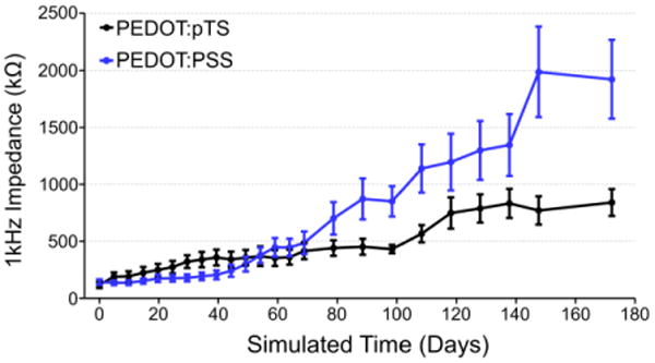
Impedance values (mean ± standard error of the mean) at 1 kHz for PEDOT:PSS and PEDOT:pTS coated carbon fiber electrodes over the simulated time from the accelerated soak test.
SEM images (figures 4(a) and 4(b)) show good adherence of both PEDOT formulations to the carbon fiber tip's outer edges. A visible void of PEDOT can be seen in the center of both PEDOT formulations, which may help to explain the steady increases in impedance.
Figure 4. SEM images of PEDOT coated and soak tested fibers.
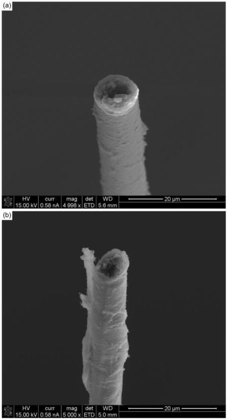
(a) SEM image of a PEDOT:pTS coated carbon fiber aged to simulated day 172.2 showing PEDOT still at the tip, but with a possible void or loss of PEDOT:pTS in the center. (b) SEM image of a PEDOT:PSS coated carbon fiber aged to simulated day 172.2 showing similar properties to that of the PEDOT:pTS coated fiber.
Based on the impedance results, all chronic implants of carbon fibers received a site coating of PEDOT:pTS.
3.2 Chronic Implant Impedance
To assess the longevity and viability of the carbon fiber arrays, 5 Long Evans rats were implanted chronically with carbon fiber arrays (n=75 fibers) in the right motor cortex. Two of those rats were also implanted with silicon electrodes (n=2 electrodes with 16 sites each) in the left motor cortex. In addition, 3 more rats were implanted with only silicon electrodes (n=2 electrodes with 16 sites each and 1 with 15 sites.). A detailed breakdown of each animal's implant type, duration, and depth, can be found in table 1. For all performance metrics, no differences were noted between animals that received one or both probe types.
Impedance measurements were taken every day for the first 13 days, every other day from days 13 to 31, and then every third day from days 31 to 91. For the two animals continued out to day 154, measurements were taken once a week after day 91. One animal, ZCR22, was sacrificed at day 73 for histological and surgical technique evaluations.
The pre-implant 1 kHz impedances (figure 5(a)) at day 0 for the carbon fibers was 128.1 ± 12.0 kΩ while those of the silicon probes were 1118.5 ± 17.4 kΩ. At day 1, post-implantation impedances for carbon fibers increased to 621.9 ± 14.8 kΩ while the silicon sites also increased to 2018.3 ± 17.6 kΩ. The impedance for both sets of probes continued upward until day 12 for the carbon fibers and day 15 for the silicon probes. At these time points the impedance values were 2044.2 ± 171.1 kΩ for the carbon fibers and 3493.7 ± 90.5 kΩ for the silicon probes.
Figure 5. Chronic implant impedances.
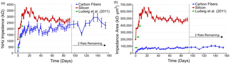
(a) Impedance values (mean ± standard error of the mean) for each probe type across time. Both electrode types saw an approximately 2 MΩ increase in impedance within the first two weeks. Values for the carbon fibers then leveled off while the silicon electrode values dropped before leveling off. Impedance values for 177 um2 silicon sites coated with PEDOT are shown in green [53]. The number of channels used for impedance analysis at each time point can be seen in figure S1. (b) Impedance values scaled by geometric surface area (mean ± standard error of the mean) for each probe type across time. Carbon fibers increased to approximately 80,000 kΩ·μm2 before leveling off, while the silicon electrode values peaked at about 650,000 kΩ·μm2 before steadying at approximately 500,000 kΩ·μm2. Similar to (a), values for 177 um2 silicon sites coated with PEDOT are shown in green [53].
Following the initial increases in impedance, the carbon fiber electrodes saw a leveling off in the impedance values which fluctuated between 1500 – 2500 kΩ from days 11 to 91. The silicon probes saw greater changes after day 9 with average impedance values ranging from approximately 2000 kΩ to just below 4000 kΩ. The large variation in average impedance for the silicon probes before and after day 31 is likely due to the drop in electrode sample size after day 31. On the final days of recording, the carbon fiber electrodes had a mean 1 kHz impedance of 2268.3 ± 253.7 kΩ at day 154 while the silicon probes had a mean 1 kHz impedance of 2742.5 ± 126.5 kΩ at day 91.
The differences in recording site sizes between the carbon fibers (36.3 μm2) and silicon probes (177 μm2) can potentially skew the impedance results as a larger site size typically results in lower impedance. When scaled for area (figure 5(b)), carbon fibers at 40 days onwards average approximately 80,000 kΩ μm2, outperforming the silicon probes which averaged 500,000 kΩ μm2. While the silicon probes used here were not functionalized with PEDOT, other studies using the same site size coated with PEDOT found chronic 1 kHz impedance reaching an average of 2210 kΩ (figure 5(a), green) or 391,170 kΩ μm2 (figure 5(b), green) between days 6 & 8 [53].
Two animals, ZCR16 and ZCR17, were not sacrificed at day 91 and were recorded from for an additional two months. Recordings were taken at one week intervals during this extended period. The carbon fiber electrode impedance values rose slightly during this period and fluctuated between 2000 – 3000 kΩ.
3.3 Chronic Unit Activity
Electrophysiology recordings followed the same points as those used for the impedance measurements. On day 1 post-implant, 65.3% of the implanted carbon fiber electrodes detected unit activity with a mean peak-to-peak amplitude of 142.1 ± 10.4 μV (figures 6(a) and 6(b)). At the same time point, the silicon electrodes detected unit activity on 3.2% of the electrodes sites with an average peak-to-peak amplitude of 59.8 ± 9.8 μV. By day 6, mean unit amplitude on the 40.3% of carbon fiber electrodes with activity continued to climb to 186.4 ± 17.1 μV while the silicon electrodes showed a small climb in activity with 6.4% of electrode sites detecting units with an average peak-to-peak amplitude of 150.2 ± 20.4 μV. At day 13, the number of carbon fiber electrodes with detectable units had slightly increased to 41.3% with an average detected peak-to-peak amplitude that was maintained at 208.1 ± 22.1 μV. During this same period, the silicon electrode detection rate remained in the single percentage range and at day 13, 3.17% of electrode sites showed an average peak-to-peak amplitude of 103.8 ± 27.0 μV.
Figure 6. Chronic unit amplitudes and percentage of channels with units.
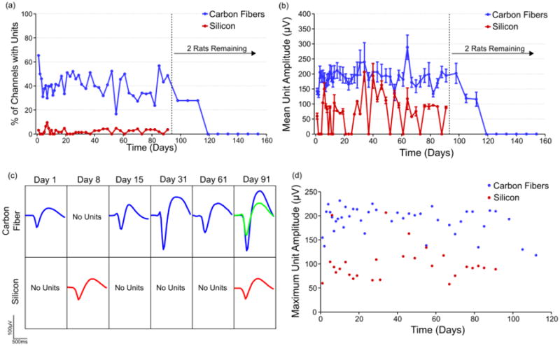
(a) On average 20% to 40% of viable carbon fiber electrodes detected unit activity across time, while silicon electrodes did so with a peak of 9.5% at day 10 and most other days detecting no unit activity. After day 91 only two rats remained in the study and the loss of their unit activity is likely explained by brain tissue swelling into the craniotomy which was discovered post mortem. The exact number of channels used for calculating the percentage of channels with units at each time point can be seen in figure S2. (b) Carbon fiber electrodes detected an average unit amplitude of 200 μV across three months. Units detected on silicon electrodes had a mean amplitude of 50 – 100 μV. All values are mean ± standard error of the mean. The exact number of units detected and used for amplitude analysis at each time point can be seen in figure S3. (c) Representative time course of detected unit activity on two different channels, one for each electrode type. (d) The mean of the largest unit detected on each carbon fiber or silicon electrode was calculated for each time point.
Following this initial spike during the first two weeks post-implant, the carbon fiber electrodes demonstrated mean peak-to-peak unit activity that stayed within the range of 150 – 250 μV through day 91. During this same period, the silicon electrodes had a very low detection rate of < 5%. When single units were detected, the mean peak-to-peak amplitude was typically between 50 – 150 μV. At day 91, 48.7% of the remaining carbon fiber implanted sites were still able to detect units with a mean peak-to-peak amplitude of 194.7 ± 21.5 μV, while 5.7% of silicon sites detected average peak-to-peak amplitude of 89.0 ± 3.6 μV. Waveforms representative of the unit activity detected for each electrode type can be seen in figure 6(c).
The two animals that were carried out to day 154 showed some continued unit activity until day 112, with 27.8% of the sites detecting a mean peak-to-peak unit amplitude of 115.8 ± 23.5 μV. After this time point, no units were detected across the remaining carbon fiber electrodes. The loss of detectable unit activity is likely due to brain tissue swelling into the craniotomy, which was discovered post-mortem.
Amplitude values obtained by averaging the largest unit on each carbon fiber channel across time (figure 6(d)) compare favorably to those seen in chronic implants of Utah arrays in primates [4].
3.4 Baseline Activity and Signal-to-Noise Ratio
In addition to unit activity, the baseline activity level (figure 7(a)) was quantified for both implant types. This was in turn was used to calculate the signal-to-noise ratio (SNR) (figure 7(b)) for both electrode styles.
Figure 7. Chronic baseline activity and SNR.
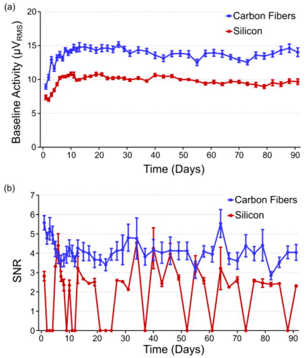
(a) Recorded baseline activity levels (mean ± standard error of the mean) for both carbon fiber and silicon electrodes for the first 91 days. Both baseline trends rise during the first two weeks of recording and then level off to steady state values. Carbon fibers demonstrate a higher overall recorded baseline level than silicon, which can be explained by a larger biological background contribution as evidenced by the high amplitude recordings reported in previous sections. (b) The SNR (mean ± standard error of the mean) for all units detected on the carbon fiber electrodes for the first 91 days. After an initial drop-off within the first week, values level off and hold between 3.5 and 5. The exact number of channels used for calculating the noise levels and SNR at each time point can be seen in figure S2.
Baseline activity levels for both the carbon fiber electrodes and silicon electrodes rose for roughly the first 11 days. The initial levels for the carbon fiber electrodes (8.9 ± 0.4 μVRMS) and silicon electrodes (6.9 ± 0.2 μVRMS) were similar at day 1 and initially peaked at days 11 (15.9 ± 0.8 μVRMS) and 10 (10.8 ± 0.2 μVRMS), respectively. After this time, both sets of baseline activity stayed remarkably consistent with the carbon fibers displaying a noise level around 15 μVRMS and the silicon electrodes around 10 μVRMS, with some slight day-to-day variations.
SNR levels for the carbon fiber electrodes initially started at 5.5 ± 0.4 and decreased to 3.3 ± 0.3 at day 6. After this time the average SNR increased and was largely maintained between 3.5 and 5 with some days deviating from this pattern. At day 91, when 4 animals remained in the study, average SNR was still 3.8 ± 0.4. After this time point SNR values rapidly dropped off (figure S4) as the remaining animals (n=2) showed decreased unit activity amplitude as seen in figure 6(b).
3.5 Histological Analysis of Implants
The microglial response to the silicon electrode is punctuated by a higher density of cells immediately surrounding the implant site (figure 8(a)). This result is typical of that seen by other groups [20,26,28,54] and agrees with previous results [41]. The global response to the carbon fiber array (figure 8(b)) is markedly different from the silicon implant. While some variability and Iba1 activity can be observed across the array implant region, such as the lower right region of the array showing signs of elevated activity, the standard error on the silicon intensity shows substantially greater variability. Analysis of all microglia images (n=2 images/electrode type) from the silicon electrodes show a consistently elevated, and at times significant (p<0.05), level of activity when compared to the microglial response surrounding the carbon fibers (figure 8(g)).
Figure 8. Chronic histology images and analysis.
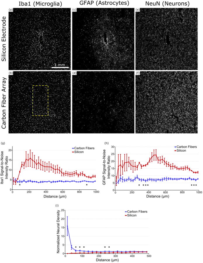
(a) & (b) Iba1 (microglia) staining around the implanted carbon fiber array and silicon electrode in ZCR19. Formation of a scar is well defined around the silicon electrode but no so around the carbon fiber array. Yellow rectangles show location and approximate size of implanted electrodes. (c) & (d) GFAP (astrocyte) staining around the implanted carbon fiber array and silicon electrode in ZCR19. Increased glial activity can be observed surrounding the silicon electrode with no obvious uptick in activity around the carbon fiber array. (e) & (f) NeuN (neuron) staining around the implanted carbon fiber array and silicon electrode in ZCR19. Neural density appears much more diminished around the silicon electrode as compared to the carbon fiber array. (g) Signal-to-noise intensity ratio of Iba1 staining around each electrode type (n=2 images/electrode type). Compared to the carbon fiber arrays the silicon electrodes maintain a more elevated level of Iba1 activity for almost all distances. (h) Signal intensity analysis of GFAP staining around each electrode type (n=2 images/electrode type). Similar to (g), the silicon electrodes show more GFAP activity as far out as 1000 μm from the implant site. (i) Normalized neural density around each electrode type (n=2 images/electrode type), illustrating the healthy neuronal population surrounding the carbon fiber arrays and a lack of neurons around the silicon electrodes. *indicates significance at p<0.05.
The difference between silicon and carbon fiber is more dramatic when examining GFAP astrocyte activity. A representative image of astrocytic activity shows the formation of a tight scar in the immediate vicinity of the silicon electrode site, with elevated activity that extends outward by as much 1000 μm (figure 8(c)). In contrast, the implant site of the carbon fiber array (figure 8(d)) shows no visible scarring regions and limited fluctuation in GFAP intensity from baseline levels. This is further corroborated by intensity analysis of all astrocyte histology images (n=2 images/electrode type), where the silicon electrodes show a sustained astrocytic response that continues out to 1000 μm from the implant site (figure 8(h)). Closer examination revealed that around the silicon implant, one animal showed a compact microglial sheath surrounded by a large activated astrocyte ring (figures S5(i) & S5(k)), while the other exhibited a more evenly distributed elevated GFAP activity. Despite this large variability in tissue reaction, elevated GFAP activity was commonly observed at the 300-400 μm radius and showed significant difference (p<0.05) compared to carbon fiber response profile, which remained steady around baseline at all distances (figure 8(h)).
Neuronal signal intensity shows a marked decrease in the area surrounding the silicon electrode (figure 8(e)). In contrast, the neuronal population surrounding the carbon fibers are well distributed and healthy with no immediately obvious declines in signal intensity (figure 8(f)). Measured normalized neural density (n=4 images/electrode type) confirm these observations with the neural density of the silicon electrodes climbing upwards as distance increases (figure 8(i)). The carbon fibers do start with a high neuronal density. This is in part due to the small tissue area in the inner bin and the relatively large tissue hole from the probe track (relative to the bin area). While the inner bins show large error bars, this data shows that neurons trend closer to the probe track of carbon fibers than the silicon shanks. At further distances, the normalized density levels off to approximately 1 and the standard errors decrease leading to significant differences (p<0.05) (figure 8(i)).
All histology images can be found in figure S5.
3.6 SEM Imaging of Explanted Carbon Fiber Electrodes
Carbon fiber electrodes from chronic implants were explanted at the end of each animal's time point and imaged (figures 9(a) – 9(d)) to better understand any physical changes the electrodes underwent.
Figure 9. SEM images of chronically implanted carbon fibers.
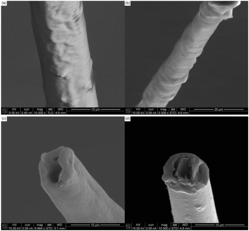
(a) & (b) SEM images of chronically implanted carbon fibers that may be experiencing parylene-c delamination. (c) & (d) SEM images of chronically implanted carbon fiber with a loss of surface roughness at the electrode tip indicating a loss of PEDOT in the center, the attachment of a thin adherence layer, or a combination of both.
Figures 9(a) and 9(b) highlight possible parylene-c delamination along the shank of the carbon fiber electrodes. This delamination, especially near the tip site can affect the probes ability to detect local activity. Figure 9(c) shows what may be a thin coating of biological material that could affect the PEDOT:pTS coating. In addition, the center of the electrode tip demonstrates a void similar to that seen with the soak test fibers (figure 4). This void may initially be caused by an uneven PEDOT:pTS electrodeposition, where more PEDOT:pTS is deposited around the edges [51]. As the PEDOT degrades, the center shows the most pronounced change as it likely has the thinnest coating [51]. This center voiding phenomenon is also seen in figure 9(d).
4. Discussion
4.1 Accelerated Aging Evaluation
This work first sought to validate a new site tip coating for the carbon fiber arrays. Accelerated soak tests were implemented to rapidly assess the viability of PEDOT:pTS as compared to PEDOT:PSS. For the first 70 simulated days, the impedances of both sets of fibers remained similar. After this time point the PEDOT:PSS fibers saw a more rapid increase in impedance as compared to the PEDOT:pTS coated fibers. The overall increase in impedance can be attributed to the slow degradation of both PEDOT formulations [45,55]. This is corroborated by SEM images which show a lack of PEDOT in the center of the electrodes. The greater stability of the PEDOT:pTS coating agrees well with results seen by others [45] and led to the decision to switch to a different formulation of PEDOT for the site coating. Using even more stable formulations of PEDOT such as those that use carbon nanotubes [56] will be explored in future studies. In addition, the use of electroplated metals such as platinum [57–60], gold [61], or iridium [62], may also serve as a more stable coating.
4.2 In Vivo Assessment of Carbon Fibers and Silicon Electrodes
Impedance levels for both probe types increased dramatically over the course of the first three weeks. These results are typical for chronically implanted electrodes [43,55,63–66]. Historically, this increase in impedance has been largely attributed to the glial scar creating a resistive layer around the probe [28,65,67]. Unfortunately, the lack of a macroscopic scar seen in previous carbon fiber work [41] and confirmed here, makes it difficult to account for the impedance increase seen with the carbon fibers. We propose a more nuanced model, which argues that even the largest of glial scars cannot fully account for the impedance rise seen in implanted Utah arrays [68], which are made of stable materials [69], have similar impedance values to the carbon fiber arrays, and in our own case where the carbon fibers do not create a traditional macroscopic scarring response [41]. Instead, dramatic increases in impedance can best be accounted for by an extremely thin resistive layer (∼0.5 μm) made up of biological material, such as cells or proteins, that is directly adhering to the recording site's surface [68].
Determining a first order approximation of this hypothesized thin layer's resistivity can be accomplished using the following equation:
| (3) |
where R = impedance at 1 kHz, ρ = resistivity, L = length or thickness, and A = area of the probe interface. It can be assumed that the probes' own internal resistances are unchanging in the first three weeks, which is a reasonable approximation for implanted metal electrodes and for the carbon fiber site coatings given the results from the soak test. Therefore, any change in resistance can be attributed to the thin adherence layer. The area of the carbon fiber electrodes was scaled by a factor of 10 to conservatively account for the PEDOT:pTS coating's increase on effective surface area [70]. This may be particularly true for porous electrode materials such as PEDOT, where its increased electrochemical surface area can be decreased by biofouling, which clogs the porous matrix [71]. Calculating the resistivity from our own results [68], leads to the values seen in table 2.
Table 2. Adherence layer resistivity.
Calculated resistivity values for adherence layers on each probe type are shown to be on the same order of magnitude and similar in value.
| Probe Type | RPre-Implant (MΩ) | RWeek 3 (MΩ) | ΔR (MΩ) | Area (μm2) | Length (μm) | ρ (Ω-cm) |
|---|---|---|---|---|---|---|
| Carbon Fiber | 0.136 | 1.75 | 1.614 | 363.1 | 0.5 | 23,435 |
| Silicon | 1.126 | 3.061 | 1.935 | 177 | 0.5 | 13,708 |
| Utah Array | 0.3787 | 0.8441 | 0.2315 | 1,100 | 0.5 | 20,476 |
Across all probe types the resistivity of the adherence layer is within the same order of magnitude and similar in value. The leveling off of all impedance values after approximately the 3rd week is likely due to the adherence layer reaching a steady state in thickness and coverage. The large unit amplitudes seen immediately and well after week 3 on the carbon fiber electrodes indicate that this thin adhesion layer is not severely affecting the ability of the fibers to record activity.
Baseline activity levels rose in a similar time course to that of the 1 kHz impedance values for both probe types, though the increase was more pronounced for the carbon fibers, which is counterintuitive given the lower impedance of the carbon fibers over time. This however, can be explained by separating the elements that contribute to overall background activity. Baseline activity is a combination of thermal and biological sources [72,73]. The lower overall impedance of the carbon fiber electrodes should lead to a lower thermal noise level; however, the overall baseline level for the fibers is larger than that of the silicon electrodes. This indicates the presence of a biological component that is larger for the carbon fiber electrodes which also points to a greater survival rate of neurons around the carbon fibers as compared to the silicon electrodes. This is also reflected by the carbon fibers' consistent ability to detect unit activity. The greater number of neurons around the carbon fiber electrodes may not always be detected as individual units, but can still contribute to the overall baseline activity, indicating a healthier local tissue environment. This is also supported by the sparse number of units detected on the silicon probes, which may possibly be suffering from mechanical failures [74]. Additionally, the silicon probes used here had small site sizes of 177 μm2, which other works have also demonstrated as having limited ability to detect unit activity [53]. This is in contrast to previous studies which used 703 μm2 [43] or 1250 μm2 [41] site sizes that were able to chronically detect unit activity. Nevertheless, on average, the amplitude of single units detected on the silicon probes was stable, albeit smaller than those detected on the carbon fibers during the 90 day implantation period.
The high unit amplitudes and relatively low baseline activity levels also contribute to a high SNR on the carbon fiber electrodes. This SNR remained stable for the first three months after an initial drop off. This drop off was caused by an increasing baseline activity level (figure 7(a)) and not decreasing unit amplitude, which was rising during the same period (figure 6(b)). Overall, the carbon fiber arrays were able to detect unit activity until day 112, or week 16, after which no more activity was detected. This can be partially attributed to the low number of animals (n=2) at the later time point. In addition, explanted brains from many of the animals showed swelling of the cortex into the craniotomy which likely caused the electrodes to move and not record from their target layer. Unfortunately, this swelling also made it difficult to separate the headcap from the brain without damaging the tissue, which ultimately led to a much lower number of animals that were available for histology.
It is important to note however, that the large unit amplitudes detected on the carbon fiber electrodes point to a minimal if not non-existent scar around the electrode. This is further corroborated by histology analysis in figure 8. These images show the formation of a scar around the silicon electrodes coupled with some decreased neuronal density and no evident scar around the carbon fiber arrays coupled with a healthy neuronal population. It is possible that the neuronal density in the bin immediately adjacent to the carbon fiber probe is slightly elevated due to the volumetric displacement of the tissue caused by the carbon fiber probes (figure 8(i)). In this case, large standard deviations in the 0-25 μm bin around the carbon fiber probes suggests that this only occurs in a percentage of probe tracks when the probe displaced the neuron. The decreases in the error bars in subsequent bins suggest that the tissue strain around the carbon fiber probes dramatically decreases by the 25-50 μm bin, and is indistinguishable by a 50 μm radius. Similar results can be observed in previous in vivo neurons around carbon fiber implants [37]. This reduced strain in the tissue and neurons may contribute to the improved recording performance, since it is understood that tissue strain adversely impacts neuronal health [35]. While previous studies show that histology can be a poor predictor of electrophysiological performance [37], these histology results correlate well with the electrophysiology results seen in this study.
5. Conclusions
This work has demonstrated the ability of carbon fiber electrodes to chronically record unit activity in the rat motor cortex up to 16 weeks. The units detected were of large amplitude and showed a high SNR. The carbon fibers greatly outperformed silicon electrodes with comparable site sizes and were also shown to detect a larger level of biological noise, indicating a healthier local tissue environment. This is also corroborated by the quality of detected unit activity. It is important to note that the stability of detected unit activity was not tracked across time as this was beyond the scope of the current study, but more analysis will be needed in this area to assess the viability of these electrodes for BMI applications. In addition, while both electrode types were implanted directly in the motor cortex no specific muscle group or region was targeted. This in turn may have led to a lower yield as this study relied on spontaneous awake activity and not activity associated with a specific task, which may have resulted in a higher electrode yield.
Further work will seek to improve the performance of the PEDOT and parylene-c coatings. Methods to reduce brain swelling and shield the carbon fibers from mechanical damage are being explored with improved array packaging and fabrication. Improvements in all of these areas could lead to high density recording arrays that cause minimal damage to the surrounding tissue and record high quality unit activity for many years.
Supplementary Material
Figure S1. Number of channels used for impedance results. For the silicon electrodes, the jump in channel count from day 23 to 25 was due to eight channels from ZCR22 being incorporated after a headstage had been repaired. The brief dip at day 55 was due to a missed time point. The decline at day 73 was due to another animal being removed from the study with four remaining until day 91. For the carbon fibers all dips and immediate recoveries, except at day 55 which was a missed time point, were due to impedance values that indicated a poor connection. Drops that occur without an immediate recovery are from channels being removed from the study due to breakage. The drop-off at day 91 is from the sacrificing of all remaining animals except for two that continued to day 154.
Figure S2. Number of channels used for electrophysiology and noise results. For the silicon electrodes, the jump in channel count from day 23 to 25 was due to eight channels from ZCR22 being incorporated after a headstage had been repaired. The brief dip at day 55 was due to a missed time point. The decline at day 73 was due to another animal being removed from the study with four remaining until day 91. For the carbon fibers, the continual decline in channel count was due to channels being removed as their 10 Hz impedance magnitudes matched those of known broken channels. The two exceptions to this were day 55, which was a missed time point, and after day 91 when only two animals remained.
Figure S3. Number of units detected for each probe type. For each probe type, the number of units detected on the valid electrophysiology channels from figure S2, is plotted over time.
Figure S4. Chronic baseline activity and SNR to day 154. (a) Recorded baseline activity levels (mean ± standard error of the mean) for both carbon fiber and silicon electrodes for all 154 days. (b) The SNR (mean ± standard error of the mean) for all units detected on the carbon fiber electrodes for all 154 days.
Figure S5. Chronic histology from carbon fiber arrays and silicon electrodes. The yellow reactangle depicted in the silicon electrode images show the approximate size and position of the electrode. In the images for the carbon fiber array the outlined yellow profile depicts the footprint of the array. (a), (b), (i), & (j) Microglia staining around implanted electrodes. More elevated responses can be seen around the silicon electrodes. (e), (f), (k), & (l) Astrocyte staining around implanted electrodes. More elevated responses can be seen around the silicon electrodes. (c), (d), (g), & (h) Neuron staining around implanted electrodes. Decreased intensity can be seen around the silicon electrodes and no obvious decreases in the carbon fiber array images.
Acknowledgments
This work was financially supported by the National Institute of Neurological Disorders and Stroke (1RC1NS068396-01, 1U01NS094375-01, & 1R01NS094396) and the McKnight Foundation.
The authors would like to thank Daryl Kipke for contributions to the experimental design. The authors would also like to thank Karen Schroeder for paper comments and assistance with statistical analysis & Kip Ludwig for assistance with recording and impedance analysis. Additional thanks to Peter Caintic for assistance with data analysis.
References
- 1.Carmena JM, Lebedev MA, Crist RE, O'Doherty JE, Santucci DM, Dimitrov DF, Patil PG, Henriquez CS, Nicolelis MAL. Learning to control a brain-machine interface for reaching and grasping by primates. PLoS Biol. 2003;1:193–208. doi: 10.1371/journal.pbio.0000042. [DOI] [PMC free article] [PubMed] [Google Scholar]
- 2.Simeral JD, Kim SP, Black MJ, Donoghue JP, Hochberg LR. Neural control of cursor trajectory and click by a human with tetraplegia 1000 days after implant of an intracortical microelectrode array. J Neural Eng. 2011;8:25027. doi: 10.1088/1741-2560/8/2/025027. [DOI] [PMC free article] [PubMed] [Google Scholar]
- 3.Hochberg LR, Serruya MD, Friehs GM, Mukand JA, Saleh M, Caplan AH, Branner A, Chen D, Penn RD, Donoghue JP. Neuronal ensemble control of prosthetic devices by a human with tetraplegia. Nature. 2006;442:164–71. doi: 10.1038/nature04970. [DOI] [PubMed] [Google Scholar]
- 4.Chestek CA, Gilja V, Nuyujukian P, Foster JD, Fan JM, Kaufman MT, Churchland MM, Rivera-Alvidrez Z, Cunningham JP, Ryu SI, Shenoy K. Long-term stability of neural prosthetic control signals from silicon cortical arrays in rhesus macaque motor cortex. J Neural Eng. 2011;8:45005. doi: 10.1088/1741-2560/8/4/045005. [DOI] [PMC free article] [PubMed] [Google Scholar]
- 5.Collinger JL, Wodlinger B, Downey JE, Wang W, Tyler-Kabara EC, Weber DJ, McMorland AJC, Velliste M, Boninger ML, Schwartz AB. High-performance neuroprosthetic control by an individual with tetraplegia. Lancet. 2013;381:557–64. doi: 10.1016/S0140-6736(12)61816-9. [DOI] [PMC free article] [PubMed] [Google Scholar]
- 6.Velliste M, Perel S, Spalding MC, Whitford AS, Schwartz AB. Cortical control of a prosthetic arm for self-feeding. Nature. 2008;453:1098–101. doi: 10.1038/nature06996. [DOI] [PubMed] [Google Scholar]
- 7.Hochberg LR, Bacher D, Jarosiewicz B, Masse NY, Simeral JD, Vogel J, Haddadin S, Liu J, Cash SS, van der Smagt P, Donoghue JP. Reach and grasp by people with tetraplegia using a neurally controlled robotic arm. Nature. 2012;485:372–5. doi: 10.1038/nature11076. [DOI] [PMC free article] [PubMed] [Google Scholar]
- 8.Taylor DM, Tillery SIH, Schwartz AB. Information conveyed through brain-control: cursor versus robot. IEEE Trans Neural Syst Rehabil Eng. 2003;11:195–9. doi: 10.1109/TNSRE.2003.814451. [DOI] [PubMed] [Google Scholar]
- 9.Schwartz AB, Cui XT, Weber DJ, Moran DW. Brain-Controlled Interfaces: Movement Restoration with Neural Prosthetics. Neuron. 2006;52:205–20. doi: 10.1016/j.neuron.2006.09.019. [DOI] [PubMed] [Google Scholar]
- 10.Davidson TJ, Kloosterman F, Wilson MA. Hippocampal Replay of Extended Experience. Neuron. 2009;63:497–507. doi: 10.1016/j.neuron.2009.07.027. [DOI] [PMC free article] [PubMed] [Google Scholar]
- 11.Cohen JY, Haesler S, Vong L, Lowell BB, Uchida N. Neuron-type-specific signals for reward and punishment in the ventral tegmental area. Nature. 2012;482:85–8. doi: 10.1038/nature10754. [DOI] [PMC free article] [PubMed] [Google Scholar]
- 12.Berke JD, Breck JT, Eichenbaum H. Striatal Versus Hippocampal Representations During Win-Stay Maze Performance. J Neurophysiol. 2009;101:1575–87. doi: 10.1152/jn.91106.2008. [DOI] [PMC free article] [PubMed] [Google Scholar]
- 13.Royer S, Sirota A, Patel J, Buzsaki G. Distinct Representations and Theta Dynamics in Dorsal and Ventral Hippocampus. J Neurosci. 2010;30:1777–87. doi: 10.1523/JNEUROSCI.4681-09.2010. [DOI] [PMC free article] [PubMed] [Google Scholar]
- 14.Bjornsson CS, Oh SJ, Al-Kofahi YA, Lim YJ, Smith KL, Turner JN, De S, Roysam B, Shain W, Kim SJ. Effects of insertion conditions on tissue strain and vascular damage during neuroprosthetic device insertion. J Neural Eng. 2006;3:196–207. doi: 10.1088/1741-2560/3/3/002. [DOI] [PubMed] [Google Scholar]
- 15.Johnson MD, Kao OE, Kipke DR. Spatiotemporal pH dynamics following insertion of neural microelectrode arrays. J Neurosci Methods. 2007;160:276–87. doi: 10.1016/j.jneumeth.2006.09.023. [DOI] [PubMed] [Google Scholar]
- 16.Kozai TDY, Marzullo TC, Hooi F, Langhals NB, Majewska AK, Brown EB, Kipke DR. Reduction of neurovascular damage resulting from microelectrode insertion into the cerebral cortex using in vivo two-photon mapping. J Neural Eng. 2010;7:46011. doi: 10.1088/1741-2560/7/4/046011. [DOI] [PMC free article] [PubMed] [Google Scholar]
- 17.Rennaker RL, Street S, Ruyle AM, Sloan AM. A comparison of chronic multi-channel cortical implantation techniques: manual versus mechanical insertion. J Neurosci Methods. 2005;142:169–76. doi: 10.1016/j.jneumeth.2004.08.009. [DOI] [PubMed] [Google Scholar]
- 18.Rousche P, Normann R. A method for pneumatically inserting an array of penetrating electrodes into cortical tissue. Ann Biomed Eng. 1992;20:413–22. doi: 10.1007/BF02368133. [DOI] [PubMed] [Google Scholar]
- 19.Potter KA, Buck AC, Self WK, Capadona JR. Stab injury and device implantation within the brain results in inversely multiphasic neuroinflammatory and neurodegenerative responses. J Neural Eng. 2012;9:46020. doi: 10.1088/1741-2560/9/4/046020. [DOI] [PubMed] [Google Scholar]
- 20.Biran R, Martin DC, Tresco PA. Neuronal cell loss accompanies the brain tissue response to chronically implanted silicon microelectrode arrays. Exp Neurol. 2005;195:115–26. doi: 10.1016/j.expneurol.2005.04.020. [DOI] [PubMed] [Google Scholar]
- 21.Edell DJ, Toi VV, McNeil VM, Clark LD. Factors influencing the biocompatibility of insertable silicon microshafts in cerebral cortex. IEEE Trans Biomed Eng. 1992;39:635–43. doi: 10.1109/10.141202. [DOI] [PubMed] [Google Scholar]
- 22.Carter RR, Houk JC. Multiple single-unit recordings from the CNS using thin-film electrode arrays. IEEE Trans Rehabil Eng. 1993;1:175–84. [Google Scholar]
- 23.Schmidt S, Horch K, Normann R. Biocompatibility of Silicon-based Electrode Arrays Implanted In Feline Cortical Tissue. J Biomed Mater Res. 1993;27:1393–9. doi: 10.1002/jbm.820271106. [DOI] [PubMed] [Google Scholar]
- 24.Turner JN, Shain W, Szarowski DH, Andersen M, Martins S, Isaacson M, Craighead H. Cerebral Astrocyte Response to Micromachined Silicon Implants. Exp Neurol. 1999;156:33–49. doi: 10.1006/exnr.1998.6983. [DOI] [PubMed] [Google Scholar]
- 25.Liu X, McCreery DB, Carter RR, Bullara LA, Yuen TGH, Agnew WF. Stability of the interface between neural tissue and chronically implanted intracortical microelectrodes. IEEE Trans Rehabil Eng. 1999;7:315–26. doi: 10.1109/86.788468. [DOI] [PubMed] [Google Scholar]
- 26.Szarowski DH, Andersen MD, Retterer S, Spence AJ, Isaacson M, Craighead HG, Turner JN, Shain W. Brain responses to micro-machined silicon devices. Brain Res. 2003;983:23–35. doi: 10.1016/s0006-8993(03)03023-3. [DOI] [PubMed] [Google Scholar]
- 27.Polikov VS, Tresco PA, Reichert WM. Response of brain tissue to chronically implanted neural electrodes. J Neurosci Methods. 2005;148:1–18. doi: 10.1016/j.jneumeth.2005.08.015. [DOI] [PubMed] [Google Scholar]
- 28.McConnell GC, Rees HD, Levey AI, Gutekunst CA, Gross RE, Bellamkonda R. Implanted neural electrodes cause chronic, local inflammation that is correlated with local neurodegeneration. J Neural Eng. 2009;6:56003. doi: 10.1088/1741-2560/6/5/056003. [DOI] [PubMed] [Google Scholar]
- 29.Grand L, Wittner L, Herwik S, Göthelid E, Ruther P, Oscarsson S, Neves H, Dombovári B, Csercsa R, Karmos G, Ulbert I. Short and long term biocompatibility of NeuroProbes silicon probes. J Neurosci Methods. 2010;189:216–29. doi: 10.1016/j.jneumeth.2010.04.009. [DOI] [PubMed] [Google Scholar]
- 30.Winslow BD, Tresco PA. Quantitative analysis of the tissue response to chronically implanted microwire electrodes in rat cortex. Biomaterials. 2010;31:1558–67. doi: 10.1016/j.biomaterials.2009.11.049. [DOI] [PubMed] [Google Scholar]
- 31.Kozai TDY, Vazquez AL, Weaver CL, Kim SG, Cui XT. In vivo two-photon microscopy reveals immediate microglial reaction to implantation of microelectrode through extension of processes. J Neural Eng. 2012;9:66001. doi: 10.1088/1741-2560/9/6/066001. [DOI] [PMC free article] [PubMed] [Google Scholar]
- 32.Ersen A, Elkabes S, Freedman DS, Sahin M. Chronic tissue response to untethered microelectrode implants in the rat brain and spinal cord. J Neural Eng. 2015;12:16019. doi: 10.1088/1741-2560/12/1/016019. [DOI] [PMC free article] [PubMed] [Google Scholar]
- 33.Guilian D, Corpuz M, Chapman S, Mansouri M, Robertson C. Reactive Mononuclear Phagocytes Release Neurotoxins After Ischemic and Traumatic Injury To the Central-nervous-system. J Neurosci Res. 1993;36:681–93. doi: 10.1002/jnr.490360609. [DOI] [PubMed] [Google Scholar]
- 34.Saxena T, Karumbaiah L, Gaupp EA, Patkar R, Patil K, Betancur M, Stanley GB, Bellamkonda R. The impact of chronic blood-brain barrier breach on intracortical electrode function. Biomater. 2013;34:4703–13. doi: 10.1016/j.biomaterials.2013.03.007. [DOI] [PubMed] [Google Scholar]
- 35.Kozai TDY, Jaquins-Gerstl AS, Vazquez AL, Michael AC, Cui XT. Brain Tissue Responses to Neural Implants Impact Signal Sensitivity and Intervention Strategies. ACS Chem Neurosci. 2015;6:48–67. doi: 10.1021/cn500256e. [DOI] [PMC free article] [PubMed] [Google Scholar]
- 36.Sawyer AJ, Tian W, Saucier-Sawyer JK, Rizk PJ, Saltzman WM, Bellamkonda RV, Kyriakides TR. The effect of inflammatory cell-derived MCP-1 loss on neuronal survival during chronic neuroinflammation. Biomater. 2014;35:6698–706. doi: 10.1016/j.biomaterials.2014.05.008. [DOI] [PMC free article] [PubMed] [Google Scholar]
- 37.Kozai TDY, Li X, Bodily LM, Caparosa EM, Zenonos GA, Carlisle DL, Friedlander RM, Cui XT. Effects of caspase-1 knockout on chronic neural recording quality and longevity: Insight into cellular and molecular mechanisms of the reactive tissue response. Biomaterials. 2014;35:9255–68. doi: 10.1016/j.biomaterials.2014.08.006. [DOI] [PMC free article] [PubMed] [Google Scholar]
- 38.Seymour JP, Kipke DR. Neural probe design for reduced tissue encapsulation in CNS. Biomaterials. 2007;28:3594–607. doi: 10.1016/j.biomaterials.2007.03.024. [DOI] [PubMed] [Google Scholar]
- 39.Stice P, Gilletti A, Panitch A, Muthuswamy J. Thin microelectrodes reduce GFAP expression in the implant site in rodent somatosensory cortex. J Neural Eng. 2007;4:42. doi: 10.1088/1741-2560/4/2/005. [DOI] [PubMed] [Google Scholar]
- 40.Skousen JL, Merriam SME, Srivannavit O, Perlin G, Wise KD, Tresco PA. Reducing surface area while maintaining implant penetrating profile lowers the brain foreign body response to chronically implanted planar silicon microelectrode arrays. Prog Brain Res. 2011;194:167–80. doi: 10.1016/B978-0-444-53815-4.00009-1. [DOI] [PubMed] [Google Scholar]
- 41.Kozai TDY, Langhals NB, Patel PR, Deng X, Zhang H, Smith KL, Lahann J, Kotov NA, Kipke DR. Ultrasmall implantable composite microelectrodes with bioactive surfaces for chronic neural interfaces. Nat Mater. 2012;11:1065–73. doi: 10.1038/nmat3468. [DOI] [PMC free article] [PubMed] [Google Scholar]
- 42.Patel PR, Na K, Zhang H, Kozai TDY, Kotov NA, Yoon E, Chestek CA. Insertion of linear 8.4 μm diameter 16 channel carbon fiber electrode arrays for single unit recordings. J Neural Eng. 2015 doi: 10.1088/1741-2560/12/4/046009. [DOI] [PMC free article] [PubMed] [Google Scholar]
- 43.Ludwig KA, Uram JD, Yang J, Martin DC, Kipke DR. Chronic neural recordings using silicon microelectrode arrays electrochemically deposited with a poly(3,4-ethylenedioxythiophene) (PEDOT) film. J Neural Eng. 2006;3:59–70. doi: 10.1088/1741-2560/3/1/007. [DOI] [PubMed] [Google Scholar]
- 44.Venkatraman S, Hendricks J, King ZA, Sereno AJ, Richardson-Burns S, Martin D, Carmena JM. In Vitro and In Vivo Evaluation of PEDOT Microelectrodes for Neural Stimulation and Recording. IEEE Trans Neural Syst Rehabil Eng. 2011;19:307–16. doi: 10.1109/TNSRE.2011.2109399. [DOI] [PubMed] [Google Scholar]
- 45.Green RA, Hassarati RT, Bouchinet L, Lee CS, Cheong GLM, Yu JF, Dodds CW, Suaning GJ, Poole-Warren LA, Lovell NH. Substrate dependent stability of conducting polymer coatings on medical electrodes. Biomaterials. 2012;33:5875–86. doi: 10.1016/j.biomaterials.2012.05.017. [DOI] [PubMed] [Google Scholar]
- 46.Hukins DWL, Mahomed A, Kukureka S. Accelerated aging for testing polymeric biomaterials and medical devices. Med Eng Phys. 2008;30:1270–4. doi: 10.1016/j.medengphy.2008.06.001. [DOI] [PubMed] [Google Scholar]
- 47.ASTM F-07 2011 Standard Guide for Accelerated Aging of Sterile Barrier Systems for Medical Devices
- 48.Paxinos G, Watson C. The Rat Brain in Stereotaxic Coordinates. Academic Press; 2007. [DOI] [PubMed] [Google Scholar]
- 49.Nunamaker EA, Kipke DR. An alginate hydrogel dura mater replacement for use with intracortical electrodes. J Biomed Mater Res Part B Appl Biomater. 2010;95B:421–9. doi: 10.1002/jbm.b.31733. [DOI] [PubMed] [Google Scholar]
- 50.Kozai TDY, Gugel Z, Li X, Gilgunn PJ, Khilwani R, Ozdoganlar OB, Fedder GK, Weber DJ, Cui XT. Chronic tissue response to carboxymethyl cellulose based dissolvable insertion needle for ultra-small neural probes. Biomaterials. 2014;35:9255–68. doi: 10.1016/j.biomaterials.2014.07.039. [DOI] [PubMed] [Google Scholar]
- 51.Cui X, Martin DC. Electrochemical deposition and characterization of poly(3,4- ethylenedioxythiophene) on neural microelectrode arrays. Sensors Actuators B Chem. 2003;89:92–102. [Google Scholar]
- 52.Harris AR, Morgan SJ, Chen J, Kapsa RMI, Wallace GG, Paolini AG. Conducting polymer coated neural recording electrodes. J Neural Eng. 2013;10:16004. doi: 10.1088/1741-2560/10/1/016004. [DOI] [PubMed] [Google Scholar]
- 53.Ludwig KA, Langhals NB, Joseph MD, Richardson-Burns SM, Hendricks JL, Kipke DR. Poly(3,4-ethylenedioxythiophene) (PEDOT) polymer coatings facilitate smaller neural recording electrodes. J Neural Eng. 2011;8:14001. doi: 10.1088/1741-2560/8/1/014001. [DOI] [PMC free article] [PubMed] [Google Scholar]
- 54.Biran R, Martin DC, Tresco PA. The brain tissue response to implanted silicon microelectrode arrays is increased when the device is tethered to the skull. J Biomed Mater Res Part A. 2007;82:169–78. doi: 10.1002/jbm.a.31138. [DOI] [PubMed] [Google Scholar]
- 55.Mandal HS, Knaack GL, Charkhkar H, McHail DG, Kastee JS, Dumas TC, Peixoto N, Rubinson JF, Pancrazio JJ. Improving the performance of poly(3,4-ethylenedioxythiophene) for brain-machine interface applications. Acta Biomater. 2014;10:2446–54. doi: 10.1016/j.actbio.2014.02.029. [DOI] [PubMed] [Google Scholar]
- 56.Kozai TDY, Catt K, Du Z, Na K, Srivannavit O, Haque RM, Seymour J, Wise KD, Yoon E, Cui XT. Chronic In Vivo Evaluation of PEDOT/CNT for Stable Neural Recordings. IEEE Trans Biomed Eng. 2016;63:111–9. doi: 10.1109/TBME.2015.2445713. [DOI] [PMC free article] [PubMed] [Google Scholar]
- 57.Arcot Desai S, Rolston JD, Guo L, Potter SM. Improving impedance of implantable microwire multi-electrode arrays by ultrasonic electroplating of durable platinum black. Front Neuroeng. 2010;3:1–5. doi: 10.3389/fneng.2010.00005. [DOI] [PMC free article] [PubMed] [Google Scholar]
- 58.Ilic B, Czaplewski D, Neuzil P, Stanczyk T, Blough J, Maclay GJ. Preparation and characterization of platinum black electrodes. J Mater Sci. 2000;35:3447–57. [Google Scholar]
- 59.Whalen JJ, III, Young J, Weiland JD, Searson PC. Electrochemical Characterization of Charge Injection at Electrodeposited Platinum Electrodes in Phosphate Buffered Saline. J Electrochem Soc. 2006;153:C834–9. [Google Scholar]
- 60.Whalen JJ, Weiland JD, Searson PC. Electrochemical Deposition of Platinum from Aqueous Ammonium Hexachloroplatinate Solution. J Electrochem Soc. 2005;152:C738–43. [Google Scholar]
- 61.Hermans A, Wightman RM. Conical Tungsten Tips as Substrates for the Preparation of Ultramicroelectrodes. Langmuir. 2006;22:10348–53. doi: 10.1021/la061209e. [DOI] [PMC free article] [PubMed] [Google Scholar]
- 62.Meyer RD, Cogan SF, Nguyen TH, Rauh RD. Electrodeposited iridium oxide for neural stimulation and recording electrodes. IEEE Trans Neural Syst Rehabil Eng. 2001;9:2–11. doi: 10.1109/7333.918271. [DOI] [PubMed] [Google Scholar]
- 63.Vetter RJ, Williams JC, Hetke JF, Nunamaker EA, Kipke DR. Chronic neural recording using silicon-substrate microelectrode arrays implanted in cerebral cortex. IEEE Trans Biomed Eng. 2004;51:896–904. doi: 10.1109/TBME.2004.826680. [DOI] [PubMed] [Google Scholar]
- 64.Prasad A, Sanchez JC. Quantifying long-term microelectrode array functionality using chronic in vivo impedance testing. J Neural Eng. 2012;9:26028. doi: 10.1088/1741-2560/9/2/026028. [DOI] [PubMed] [Google Scholar]
- 65.Williams JC, Hippensteel JA, Dilgen J, Shain W, Kipke DR. Complex impedance spectroscopy for monitoring tissue responses to inserted neural implants. J Neural Eng. 2007;4:410–23. doi: 10.1088/1741-2560/4/4/007. [DOI] [PubMed] [Google Scholar]
- 66.Kozai TDY, Du Z, Gugel ZV, Smith MA, Chase SM, Bodily LM, Caparosa EM, Friedlander RM, Cui XT. Comprehensive chronic laminar single-unit, multi-unit, and local field potential recording performance with planar single shank electrode arrays. J Neurosci Methods. 2015;242:15–40. doi: 10.1016/j.jneumeth.2014.12.010. [DOI] [PMC free article] [PubMed] [Google Scholar]
- 67.Sankar V, Patrick E, Dieme R, Sanchez JC, Prasad A, Nishida T. Electrode impedance analysis of chronic tungsten microwire neural implants: understanding abiotic vs. biotic contributions. Front Neuroeng. 2014;7:1–12. doi: 10.3389/fneng.2014.00013. [DOI] [PMC free article] [PubMed] [Google Scholar]
- 68.Malaga KA, Schroeder KE, Patel PR, Irwin ZT, Thompson DE, Bentley JN, Lempka SF, Chestek CA, Patil PG. Data-driven model comparing the effects of glial scarring and interface interactions on chronic neural recordings in non-human primates. J Neural Eng. 2016;13:16010. doi: 10.1088/1741-2560/13/1/016010. [DOI] [PubMed] [Google Scholar]
- 69.Negi S, Bhandari R, Rieth L, Solzbacher F. In vitro comparison of sputtered iridium oxide and platinum-coated neural implantable microelectrode arrays. Biomed Mater. 2010;5:15007. doi: 10.1088/1748-6041/5/1/015007. [DOI] [PubMed] [Google Scholar]
- 70.Cui X, Hetke JF, Wiler JA, Anderson DJ, Martin DC. Electrochemical deposition and characterization of conducting polymer polypyrrole/PSS on multichannel neural probes. Sensors Actuators A Phys. 2001;93:8–18. [Google Scholar]
- 71.Kozai TDY, Alba NA, Zhang H, Kotov NA, Gaunt RA, Cui XT. Nanostructured Coatings for Improved Charge Delivery to Neurons. In: De Vittorio M, Martiradonna L, Assad J, editors. Nanotechnology and Neuroscience: Nano-electronic, Photonic and Mechanical Neuronal Interfacing. Springer; New York: 2014. pp. 71–134. [Google Scholar]
- 72.Lempka SF, Johnson MD, Moffitt MA, Otto KJ, Kipke DR, McIntyre CC. Theoretical analysis of intracortical microelectrode recordings. J Neural Eng. 2011;8:45006. doi: 10.1088/1741-2560/8/4/045006. [DOI] [PMC free article] [PubMed] [Google Scholar]
- 73.Lempka SF, Johnson MD, Barnett DW, Moffitt MA, Otto KJ, Kipke DR, McIntyre CC. Optimization of Microelectrode Design for Cortical Recording Based on Thermal Noise Considerations. 2006 Annu Int Conf IEEE Eng Med Biol Soc. 2006:3361–4. doi: 10.1109/IEMBS.2006.259432. [DOI] [PubMed] [Google Scholar]
- 74.Kozai TDY, Catt K, Li X, Gugel ZV, Olafsson VT, Vazquez AL, Cui XT. Mechanical failure modes of chronically implanted planar silicon-based neural probes for laminar recording. Biomaterials. 2015;37:25–39. doi: 10.1016/j.biomaterials.2014.10.040. [DOI] [PMC free article] [PubMed] [Google Scholar]
Associated Data
This section collects any data citations, data availability statements, or supplementary materials included in this article.
Supplementary Materials
Figure S1. Number of channels used for impedance results. For the silicon electrodes, the jump in channel count from day 23 to 25 was due to eight channels from ZCR22 being incorporated after a headstage had been repaired. The brief dip at day 55 was due to a missed time point. The decline at day 73 was due to another animal being removed from the study with four remaining until day 91. For the carbon fibers all dips and immediate recoveries, except at day 55 which was a missed time point, were due to impedance values that indicated a poor connection. Drops that occur without an immediate recovery are from channels being removed from the study due to breakage. The drop-off at day 91 is from the sacrificing of all remaining animals except for two that continued to day 154.
Figure S2. Number of channels used for electrophysiology and noise results. For the silicon electrodes, the jump in channel count from day 23 to 25 was due to eight channels from ZCR22 being incorporated after a headstage had been repaired. The brief dip at day 55 was due to a missed time point. The decline at day 73 was due to another animal being removed from the study with four remaining until day 91. For the carbon fibers, the continual decline in channel count was due to channels being removed as their 10 Hz impedance magnitudes matched those of known broken channels. The two exceptions to this were day 55, which was a missed time point, and after day 91 when only two animals remained.
Figure S3. Number of units detected for each probe type. For each probe type, the number of units detected on the valid electrophysiology channels from figure S2, is plotted over time.
Figure S4. Chronic baseline activity and SNR to day 154. (a) Recorded baseline activity levels (mean ± standard error of the mean) for both carbon fiber and silicon electrodes for all 154 days. (b) The SNR (mean ± standard error of the mean) for all units detected on the carbon fiber electrodes for all 154 days.
Figure S5. Chronic histology from carbon fiber arrays and silicon electrodes. The yellow reactangle depicted in the silicon electrode images show the approximate size and position of the electrode. In the images for the carbon fiber array the outlined yellow profile depicts the footprint of the array. (a), (b), (i), & (j) Microglia staining around implanted electrodes. More elevated responses can be seen around the silicon electrodes. (e), (f), (k), & (l) Astrocyte staining around implanted electrodes. More elevated responses can be seen around the silicon electrodes. (c), (d), (g), & (h) Neuron staining around implanted electrodes. Decreased intensity can be seen around the silicon electrodes and no obvious decreases in the carbon fiber array images.