Abstract
We present a multiphoton microscope designed for mesoscale imaging of human skin. The system is based on two-photon excited fluorescence and second-harmonic generation, and images areas of ~0.8x0.8 mm2 at speeds of 0.8 fps (800x800 pixels; 12 frame averages) for high signal-to-noise ratio, with lateral and axial resolutions of 0.5µm and 3.3µm, respectively. The main novelty of this instrument is the design of the scan head, which includes a fast galvanometric scanner, optimized relay optics, a beam expander and high NA objective lens. Computed aberrations in focus are below the Marechal criterion of 0.07λ rms for diffraction-limited performance. We demonstrate the practical utility of this microscope by ex-vivo imaging of wide areas in normal human skin.
OCIS codes: (180.4315) Nonlinear microscopy, (180.0180) Microscopy, (170.2520) Fluorescence microscopy
1. Introduction
In vivo multiphoton microscopy (MPM) holds promise as an important research and clinical tool for label-free imaging in human skin. The clinical applications of in vivo label-free MPM span from skin cancer detection and diagnosis [1–4], to characterizing and understanding keratinocyte metabolism [5], skin aging [6, 7], pigment biology [8–10], and cosmetic treatments [11–13]. MPM is based on laser-scanning microscopy, a technique that utilizes a focused laser beam that is raster-scanned across the sample to create high-resolution images. A 3D-view of the skin can be reconstructed by scanning at multiple depths. Importantly, high-resolution imaging is combined with a label-free contrast mechanism. MPM contrast in skin is mainly derived from second harmonic generation (SHG) of collagen and two-photon excited fluorescence (TPEF) of tissue components such as the co-factors NADH and FAD + , elastin, keratin, and melanin.
Clinical examination crucially relies on the ability to quickly examine large tissue areas and rapidly zoom in to regions of interest. Skin lesions often show irregularity in color and appearance, especially when they start to progress towards malignancy. Examination of the entire lesion is essential to avoid false negative diagnostic assessments. Therefore, imaging of large field of views (FOVs) and automatic translation of the inspected area are practical requirements for reliable clinical imaging. Commercial clinical microscopes based on MPM and reflectance confocal microscopy (RCM) have implemented automatic translation of the imaging area [2, 14]. However, the initial FOV is typically limited to less than 0.5x0.5 mm2 and thus, assessing large areas of several mm2 at different depths may be time consuming and impractical for clinical use. In an ideal system, large FOV and automatic translation of the imaging area is complemented by fast image acquisition with high detection sensitivity in order for such a system to be of clinical use for rapid assessment of skin lesions.
In recent years, several advances in nonlinear optical microscopy (NLOM) have led to imaging systems with appreciable FOVs [15, 16]. P.S. Tsai et al. reported on the development of an NLOM system capable of imaging up to 80 mm2 at a maximum speed of 5mm/ms at the expense of lateral resolution (between 1.2 μm and 2 μm across the entire FOV) [16]. This microscope was applied for imaging resting-state vasomotion across both hemispheres of a murine brain through a transcranial window without the need to stich adjacent imaging areas. Negrean and Mansvelder presented an in-depth optimization study of scan and tube lens designs for minimizing optical aberrations associated with large angle scanning [17]. Both aforementioned studies used conventional galvanometer scanners. Higher scan speeds provided by rotating polygon mirrors or resonant galvanometric scanners have been previously implemented in NLOM-based systems for several applications [18–21], including human skin [19] imaging. The study reported in Ref [21]. presents NLOM images with FOV of 800x600 μm2 acquired in vivo in mouse skin, with high theoretical spatial resolution, at fast scan rates. This work did not include an evaluation of the optical performance of the system. Mostly, all other studies advanced the NLOM systems to improve either the scanning speed or the field of view as required by the application of interest. Optimization of both parameters was achieved at the expense of spatial resolution [16].
In this work, we describe a systematic analysis of MPM system designed for rapidly generating images with large FOVs without compromising resolution. This system is designed specifically for clinical imaging of human skin, and features a large FOV of 800x800 μm2 acquired at a maximum frame rate of 10 frames/s, while maintaining sub-micron spatial resolution. A field of view of 1.2x1.2 mm2 can be obtained at the expense of increased field curvature. We discuss the performance of the system in detail, both theoretically and experimentally, and demonstrate its practical utility by ex-vivo imaging of wide areas in normal human skin at fast scan rates. A brief summary of this work was previously reported in Ref [22].
2. Basic description of the MPM instrument and main optical design considerations
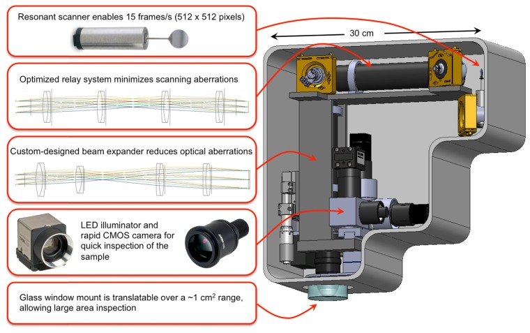
The main elements of the scan head and imaging optics design are shown in Fig. 1. The system includes a fast galvanometric scanner, relay optics, a beam expander and a high NA objective lens. The selection of the objective determines the main optical design considerations of the microscope. We have chosen to optimize the system based on the 25x, 1.05 NA water immersion lens from Olympus (XLPL25XWMP), one of the premier tissue imaging objectives that features a long working distance of 2 mm. This objective has a focal distance of 7.2 mm (based on a tube lens focal length of 180 mm) and an entrance pupil diameter of approximately 15 mm. We describe below in detail the main components of the system.
Fig. 1.
Schematic and overview of the main elements of the scan head.
2.1 Implementation of fast imaging acquisition
Our design is based on a resonant scanner (Cambridge Technology), which operates at 4 kHz and supports a frame rate of ~10 frames/s for an image of 800 x 800 pixels. Once relevant areas have been identified, it is possible to take high-density pixel maps of 1600 x 1600 pixels at a rate of 0.2 seconds per frame. However, high signal-to-noise ratio (SNR) images require averaging of several frames. We found that averaging 4 frames is sufficient for the fast scanning mode, which we use for fast visualization of features in the sample, while average of 8 to 12 frames is necessary for the slow scanning mode, employed for recording images with SNR values higher than 20. Therefore, the fast scanning mode used has a rate of 0.4 seconds per frame (average of 4 frames of 800x800 pixels), while the slow scanning mode has a rate of 1.6 to 2.4 seconds per frame (average of 8 to 12 frames of 1600x1600 pixels).
Along with the fast mechanical scanner, high-speed acquisition electronics is needed to capture the data. We use a high-speed 4 channel 14-bit analog-to-digital (A/D) converter to process the data. The A/D card features a sampling rate of 120 MS/s and a 1GS memory, more than sufficient to acquire imaging data at 8 frames/s. The card is controlled through a C + + based software and a GUI for the final user-friendly version of scanning software (SlideBook, Intelligent Imaging Innovations, Denver, CO).
The useful aperture for the resonant scanner is 12 mm x 9.25 mm (X-axis), and 10 mm for the slow axis Y mirror.
2.2 Implementation of a wide field of view (FOV)
2.2.1 Optical design considerations
In a laser-scanning microscope, the FOV is determined by the objective focal length (fobj) and the scanning angle at the back aperture of the objective (Φ):
| (1) |
where Φ is measured relative to the optical axis, corresponding to half of the full scanning angle at the corner of the FOV. A large FOV is achieved for long objective focal lengths and large scanning angles. Both of these parameters result in limited spatial resolution, as long focal lengths correspond to low magnification and low NA objectives, while large scanning angles lead to optical aberrations such as coma and astigmatism. Once the focal length is determined based on the selection of the objective, the FOV is limited by the scanning angle. The scanning angle of the mirrors depends on the magnification of the system. Low magnification is required to minimize the scanning angle and optical aberrations such as coma and astigmatism. The objective entrance pupil diameter determines the beam size before objective. Overfilling of the back aperture is needed to utilize the full NA of the objective lens, a task performed by the beam expander, which consists of scan and tube lens elements. The beam expander of our system has a 1.8x magnification, determined by the maximum beam diameter of 9 mm allowed by the scanning mirror and the objective entrance pupil diameter, 15 mm. A common limitation of the FOV in conventional laser-scanning microscopes, where the scanning mirrors are placed in proximity, is related to the lateral motion of the laser beam at the back aperture of the objective. This is due to the beam displacement by the first mirror on the second mirror, which for large angles can lead to vignetting and reduction of the FOV [23, 24]. To address this limitation, we employed a relay lens system between the scanning mirrors.
A FOV of 0.8 x 0.8 mm2 requires an angle Φ of 4.5° Eq. (1) at the back aperture of the objective. The corresponding scanning angles before the beam expander and the relay lens system are 8.1 o and 5.7 o, respectively.
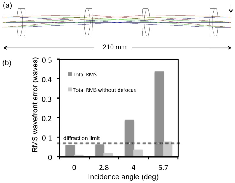
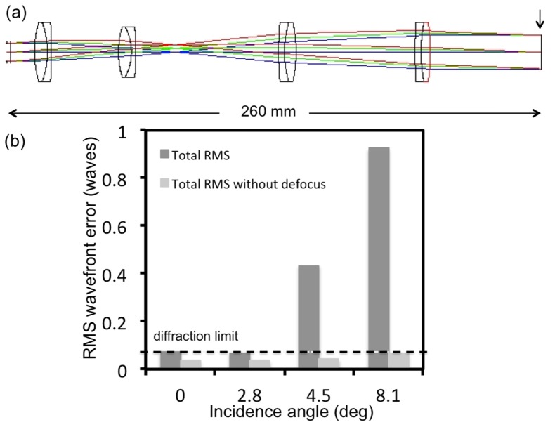
Simulation and optimization of both the beam expander and the relay imaging systems were carried out using a computer-aided design software (ZEMAX, Radiant ZEMAX LLC). The design was based on the availability of off-the-shelf lenses for a cost-effective final solution. The optical systems were designed and optimized such that the root mean square (RMS) wavefront error was not larger than 0.07 λ, a criterion associated with diffraction-limited performance (Maréchal criterion). We performed the optimization for maximum scanning angles of 8.1° and 5.7° before the beam expander and the relay lens system, respectively, a Gaussian beam diameter of 9 mm (FW1/e2M) and a beam expander magnification of 1.8. These parameters give rise to a beam diameter of 16.2 mm after the expander, overfilling the back aperture of the objective (XLPL25XWMP, Olympus) and to a FOV of 800x800 μm2. The primary optimization wavelength was 800 nm, the wavelength of interest for our skin imaging application. We evaluate the performance of the beam expander and the relay lens system by evaluating the corresponding RMS wavefront distribution with respect to the incidence angle. The wavefront error of defocus, caused by field curvature with respect to the focal plane, is the main optical aberration that affects the total RMS wavefront of both systems. However, since the system presented in this manuscript was developed mainly for applications related to thick tissue imaging, such as human skin, defocus does not play a critical role in the overall quality of the image. Therefore the RMS wavefront distribution excluding the defocus term is the relevant figure of merit for the optical system used in our application. We describe below in detail the components and the overall performance of the relay lens system and the beam expander.
2.2.2 Optical design of the relay lens system
The 1:1 relay lens imaging system (Fig. 2(a)) consists of four doublet achromatic lenses (026-1130, Optosigma and PAC046, Newport – 2 pairs of each). The RMS wavefront error at 0-degree incidence angle corresponding to 800 nm excluding the defocus term is 0.01λ. The RMS wavefront distribution with respect to the incidence angle indicates a diffraction-limited performance for almost the entire FOV when the defocus term is excluded (Fig. 2(b)).
Fig. 2.
Relay system-layout and RMS wavefront error. a) optical layout; arrow indicates the image surface at which the aberrations were calculated b) The RMS wavefront error as a function of incidence angle with respect to the diffraction limited value (horizontal line)
2.2.3 Optical design of the beam expander
The beam expander imaging system (Fig. 3(a)) consists of four doublet achromatic lenses (AC300-080-B Thorlabs; PAC046, Newport; 026-1180 and 026-1220 Optosigma). The RMS wavefront error at 0-degree incidence angle corresponding to 800 nm excluding the defocus term is 0.04λ. The RMS wavefront distribution with respect to the incidence angle indicates a diffraction-limited performance for the entire FOV when the defocus term is excluded (Fig. 3(b)).
Fig. 3.
Beam expander-layout and RMS wavefront error. a) optical layout with the vertical line indicating the surface at which the aberrations are reported b) The RMS wavefront error as a function of incidence angle with respect to the diffraction limited value (horizontal line)
The optical aberration that has the most significant contribution to the total RMS wavefront error for both systems, is the defocus, caused by field curvature with respect to the focal plane. The Zemax simulation estimates a total field curvature of 13 μm, considering the objective used in our experiments and 800 nm excitation wavelength. We measured a field curvature of 9 μm introduced by the objective alone. Hence, we expect an overall field curvature of 22 μm. In principle, both the relay and the beam expander configurations can be further optimized when allowing for longer optical pathlengths. However, the compactness of the system was an important criterion considered in the design.
2.3 Optimization of signal detection
Fast image acquisition requires an efficient and high sensitivity signal detection system. We achieve this in two ways. First, we have designed signal collection optics that capture the maximum amount of radiation emitted in the epi-direction. Using ZEMAX simulations, we optimized the optics components for collection efficiency, as shown in Fig. 4. We use a first dichroic mirror to separate the excitation and the emission signals (FF705-Di01, Semrock, Inc.) and a second dichroic mirror (FF506-Di03, Semrock, Inc.) to split the TPEF and SHG detection channels defined by the emissions filters: FF01-720/SP and FF01-535/150 (Semrock, Inc.) for TPEF; and FF01-375/110 for SHG. Second, we selected high sensitivity photodetectors (Hamamatsu R9880-20 and R9880-210), chosen for their high detection sensitivities in the visible range of the spectrum.
Fig. 4.
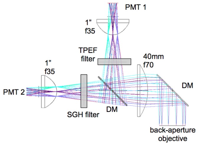
Schematic for efficient collection of signals in the epi-direction. Diameter and focal length of the lenses were optimized in ZEMAX for maximum collection of photons. Dichroic mirrors (DM) separate the signal into TPEF and SHG components. Sensitive photomuliplier tubes (PMT) are used.
The basic imaging properties of the scan head are summarized in Table 1.
Table 1. Basic imaging properties of the scan head.
| Property | Specification | Comment |
|---|---|---|
| Frame rate | 800 x 800 pixels: 10 fps-single frame to 0.8 fps-12 frames averaged for SNR>20 1600 x 1600 pixels: 5 fps-single frame to 0.4 fps- 12 frames averaged for SNR>20 |
High frame rate for rapid browsing of tissue |
| Frame dimension | 800x800 to1600x1600 | Image dimension controllable by software |
| FOV | 0.8 x 0.8 mm2 | Wide FOV covers larger tissue areas |
| Lateral translation | 1.0 cm | Enables mesoscale exploration of tissue |
| Resolution | 0.5 µm lateral; 3.3 µm axial | High resolution |
| Imaging depth | 0.100-0.250 mm | Sufficient to capture epidermis and reach the dermis |
| Detection channels | TPEF; SHG | NLO signals detected with high sensitivity PMTs |
| Bright field | LED illuminator plus CCD | Bright field reflection detected in epi-mode |
3. MPM imaging system performance
The data presented in the following sections of the manuscript were acquired using a bench-top prototype of the microscope described in Fig. 1. We employed a Ti:Sapphire laser (MIRA 900, Coherent, Inc.), 800 nm, 120 fs, 76 MHz as excitation light source in all experiments further presented. Pre-chirping for compensation of pulse broadening at the sample was not included at this stage of the development. The average laser power used in all ex vivo imaging experiments on human skin was ~30mW at the sample.
3.1 Point spread function (PSF)
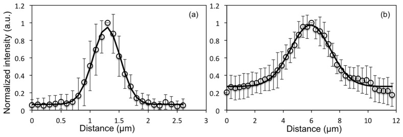
We used 0.2 µm yellow-green (505/515) fluorescent beads (Molecular Probes, Eugene, Oregon) for measuring the lateral and the axial resolution. We measured a lateral PSF of 0.5 ± 0.1 µm and an axial PSF of 3.3 ± 0.5 µm (full-width half maximum of Gaussian fit) for the 800 nm excitation wavelength. Figure 5 shows lateral and axial cross sections based on average of measurements on 15 beads.
Fig. 5.
MPM imaging system resolution. Point spread function representing (a) lateral resolution - FWHM = 0.5 µm and (b) axial resolution - FWHM = 3.3 µm. Data were acquired at 800 nm excitation wavelength and represent the fluorescence average of 15 beads. The error bars represent the standard deviation of the fifteen measurements.
The optical resolution determines the maximum performance of the system regarding the resolvable size of the lateral and axial features. The maximum digital sampling currently available for our system, 1600x1600 pixels, provides a pixel size of 0.5 µm when imaging a FOV of 800x800 µm2. Since the lateral spatial resolution in the system is 0.5 µm as well, the FOV is slightly undersampled.
3.2 Comparison of home-built MPM-based imaging platform with a commercial system using the same objective
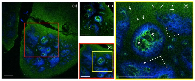
To compare the FOVs of the home-built and of a commercial Olympus laser-scanning microscope (FV300), we imaged the same sample with each microscope using the same objective (Olympus, XLPL25XWMP). For an adequate comparison of the maximum FOV covered by each microscope, the scanning was set such that the FOVs would show similar uniformity of the TPEF signal from a fluorescein sample. Therefore a FOV of 820 x 820 µm2 for the home-built microscope corresponded to an area of 370 x 370 µm2 scanned by using the Olympus microscope. To illustrate this comparison we used images acquired from a sample of formalin-fixed human skin tissue. Figure 6 shows representative images of the dermo-epidermal junction (DEJ) of human skin acquired at a depth of 50 µm, at the maximum FOV using the home-built microscope (Fig. 6(a)) and the commercial Olympus microscope (Fig. 6(b)). To compare the features resolved in similar FOVs, an image of the DEJ was acquired with the home-built microscope over an area of 370 x 370 µm2 (Fig. 6(c)). Figure 6(d) represents a close-up MPM image of keratinocytes, elastin and collagen fibers of the DEJ.
Fig. 6.
Ex-vivo human skin imaging-comparison of home-built MPM-based imaging platform with a commercial system using the same objective. (a) Dermo-epidermal junction (DEJ) imaged with the home-built microscope by SHG (blue) and TPEF (green). TPEF signal originates from keratin in the epidermal keratinocytes and from elastin fibers (arrows) in the superficial papillary dermis, while SHG highlights the collagen fibers. (b) A similar location of the DEJ in the skin sample acquired with a commercial Olympus microscope over an area of 370 x 370 µm2 by using the same objective as in the home-built microscope. (c) MPM image of the DEJ acquired with the home-built microscope over an area of 370 x 370 µm2 for comparison with the image in (b) acquired with the Olympus microscope. The image in (c) corresponds to the inset in (a). (d) MPM image of the DEJ corresponding to the inset in (c) showing keratinocytes (full line arrows), elastin fibers (arrow heads) and collagen fibers (dashed line arrows). Images were acquired at 50µm depth in the sample. Scale bar is 100 µm.
The images shown in Fig. 6 provided similar SNR value when acquired with a speed of 1.2s/image (0.1s/frame x 12 frames averaging) for 800x800 pixels for the home-built system (effective pixel dwell time: 1.9 μs) and with 2s/image (1s/frame x 2 frames averaging) for 512x512 pixels for the Olympus microscope (effective pixel dwell time: 7.6 μs).
3.3 MPM depth imaging of human skin (ex-vivo)
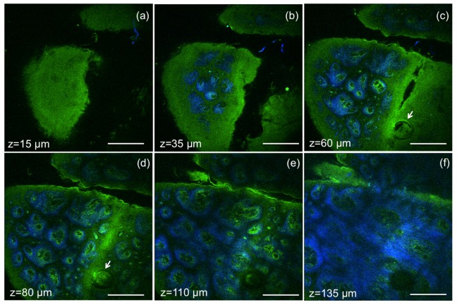
Validation of the MPM imaging system included the evaluation of its ability to acquire images in human skin ex vivo by rapidly scanning large areas at different depths, without compromising sub-cellular resolution. Representative images acquired at different depths in a sample of formalin-fixed human skin tissue, are shown in Fig. 7. Images of 820 x 820 µm2, 800x800 pixels, were acquired at an effective speed of 1.2 s/frame, which includes averaging over 12 frames. Horizontal sections (x-y scans) in Fig. 7 show images of the epidermis (Fig. 7(a)), basal cells surrounding the dermal papilla in the dermo-epidermal junction (DEJ) (Fig. 7(b)-7(e)), collagen and elastin fibers at different depths in the DEJ and in the dermis (Fig. 7 c-f). A complete z-stack of 60 images acquired ex vivo to a depth of 180 µm with a step of 3 µm is included in Supplemental material (Visualization 1 (7.4MB, AVI) ), along with a z-stack acquired for a FOV of 410x410 µm2 to illustrate the resolved features of epidermal keratinocytes and fibrilar structures in the dermis (Visualization 2 (10MB, AVI) ). The total acquisition time for each z-stack was 1.2 min. A field of view of 1.2x1.2 mm2 can be obtained by this imaging system at the expense of increased field curvature.
Fig. 7.
Ex vivo MPM imaging of human skin at different depths. MPM horizontal sections show images of (a) epidermis (z = 15µm); (b-e) basal cells (green) surrounding dermal papilla (blue) at the dermo-epidermal junction (z = 35µm, 60 µm, 80 µm, 110 µm); arrows indicate hair follicle (c, d); (f) collagen (blue) and elastin (green) fibers in the papillary dermis (z = 135µm). Scale bar is 200 µm.
3.4 Mesoscale MPM imaging
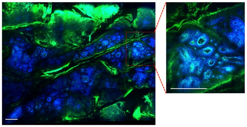
To enhance its practical utility in clinical setting, in addition to large FOV, system performance is aided by the capability to rapidly inspect tissue architecture on the sub-cm2 scale, a scale characteristic for overall lesion morphology. For this purpose, we used a servo-controlled miniature translation stage for scanning the sample in order to test the mesoscale imaging capability of the system. The stage has an extendable range of 1 cm along both lateral coordinates A representative image of a 3.1 x 2.5 mm2 area of a DEJ in a human skin sample (discarded tissue fixed in formalin) is shown in Fig. 8. The image includes a mosaic of 20 frames. Each frame of 1600x1600 pixels was acquired in 2.4 s, which includes an average of 12 frames. The mosaic image was acquired in 2 minutes.
Fig. 8.
Ex vivo MPM mesoscale imaging of human skin. MPM image of the DEJ in human skin showing keratin in skin folds (green) and fibrilar structure of dermal papilla (collagen fibers-blue; elastin fibers-green). The wide area image (3.1 x 2.5 mm2) includes a mosaic of 20 frames and was acquired in 2 minutes. The image shown as inset was acquired as single frame in 2.4 s. Scale bar is 0.25 mm.
4. Discussion and conclusion
The work described in this manuscript addresses two main technical challenges related to MPM skin imaging: limited field of view and slow acquisition rate of large skin areas. Optimizing these parameters is imperative for advancing the MPM technology to become an efficient skin imaging tool in the clinic. The MPM-based imaging platform proposed here includes components that have been previously employed separately in laser scanning microscopes to address either one of the aforementioned limitations. Thus, the system includes a fast galvanometric scanner to increase the acquisition rate and custom-designed relay optics and beam expander to minimize scanning and optical aberrations, and optimize the field of view. The simulation of the optical performance for the relay and beam expander systems showed that computed aberrations in focus were below the Marechal criterion of 0.07λ rms for diffraction-limited performance. The RMS wavefront distribution with respect to the incidence angle estimated a diffraction-limited performance for almost all FOV, when defocus caused by field curvature was excluded. Importantly, the system was optimized based on an objective that features low magnification and high NA (Olympus 25X, 1.05NA water immersion lens, 1mm working distance), allowing imaging at sub-micron resolution. We demonstrate the practical utility of this microscope by rapid imaging wide FOVs in normal human skin ex-vivo. The MPM-based instrument proposed here is capable of imaging 0.8x0.8 mm2 skin areas at sub-micron resolution and rates that range between 0.4 to 2.4 seconds per frame (when averaging 4 to 12 frames for high SNR). This represents a 4x improvement in the FOV and scanning rate (effective pixel dwell time) when compared to the images acquired with a commercial microscope using the same objective. We do not expect any change in the frame rate for in vivo human skin imaging experiments. The SHG and TPEF signal intensities from the dermis do not usually change much through tissue fixation. The TPEF signal intensity from NADH in the epidermal keratinocytes is in fact higher in live tissue.
While this is a significant improvement in acquisition speed and scanning field of view, further optimization is possible by implementing custom-designed optics to extend the diffraction-limited performance over the entire FOV, while yet maintaining a compact configuration. The current design represents a practical solution that balances performance, size and cost. It was tailored specifically to maximize FOV, image speed and signal collection from key molecular components in skin tissue. The technical advancements described in this manuscript, if implemented and further optimized, can significantly enhance the practical use of the nonlinear optical microscopy in clinical settings.
Funding
Support for this work was provided by the NIH NIBIB Laser Microbeam and Medical Program (LAMMP, P41-EB015890). Beckman Laser Institute programmatic support from the Arnold and Mabel Beckman Foundation is also acknowledged.
References and links
- 1.Dimitrow E., Ziemer M., Koehler M. J., Norgauer J., König K., Elsner P., Kaatz M., “Sensitivity and specificity of multiphoton laser tomography for in vivo and ex vivo diagnosis of malignant melanoma,” J. Invest. Dermatol. 129(7), 1752–1758 (2009). 10.1038/jid.2008.439 [DOI] [PubMed] [Google Scholar]
- 2.Ulrich M., Klemp M., Darvin M. E., König K., Lademann J., Meinke M. C., “In vivo detection of basal cell carcinoma: comparison of a reflectance confocal microscope and a multiphoton tomograph,” J. Biomed. Opt. 18(6), 061229 (2013). 10.1117/1.JBO.18.6.061229 [DOI] [PubMed] [Google Scholar]
- 3.Balu M., Kelly K. M., Zachary C. B., Harris R. M., Krasieva T. B., König K., Durkin A. J., Tromberg B. J., “Distinguishing between benign and malignant melanocytic nevi by in vivo multiphoton microscopy,” Cancer Res. 74(10), 2688–2697 (2014). 10.1158/0008-5472.CAN-13-2582 [DOI] [PMC free article] [PubMed] [Google Scholar]
- 4.Balu M., Zachary C. B., Harris R. M., Krasieva T. B., König K., Tromberg B. J., Kelly K. M., “In Vivo Multiphoton Microscopy of Basal Cell Carcinoma,” JAMA Dermatol. 151(10), 1068–1074 (2015). 10.1001/jamadermatol.2015.0453 [DOI] [PMC free article] [PubMed] [Google Scholar]
- 5.Balu M., Mazhar A., Hayakawa C. K., Mittal R., Krasieva T. B., König K., Venugopalan V., Tromberg B. J., “In vivo multiphoton NADH fluorescence reveals depth-dependent keratinocyte metabolism in human skin,” Biophys. J. 104(1), 258–267 (2013). 10.1016/j.bpj.2012.11.3809 [DOI] [PMC free article] [PubMed] [Google Scholar]
- 6.Koehler M. J., König K., Elsner P., Bückle R., Kaatz M., “In vivo assessment of human skin aging by multiphoton laser scanning tomography,” Opt. Lett. 31(19), 2879–2881 (2006). 10.1364/OL.31.002879 [DOI] [PubMed] [Google Scholar]
- 7.Liao Y. H., Kuo W. C., Chou S. Y., Tsai C. S., Lin G. L., Tsai M. R., Shih Y. T., Lee G. G., Sun C. K., “Quantitative analysis of intrinsic skin aging in dermal papillae by in vivo harmonic generation microscopy,” Biomed. Opt. Express 5(9), 3266–3279 (2014). 10.1364/BOE.5.003266 [DOI] [PMC free article] [PubMed] [Google Scholar]
- 8.Dancik Y., Favre A., Loy C. J., Zvyagin A. V., Roberts M. S., “Use of multiphoton tomography and fluorescence lifetime imaging to investigate skin pigmentation in vivo,” J. Biomed. Opt. 18(2), 026022 (2013). 10.1117/1.JBO.18.2.026022 [DOI] [PubMed] [Google Scholar]
- 9.Krasieva T. B., Stringari C., Liu F., Sun C. H., Kong Y., Balu M., Meyskens F. L., Gratton E., Tromberg B. J., “Two-photon excited fluorescence lifetime imaging and spectroscopy of melanins in vitro and in vivo,” J. Biomed. Opt. 18(3), 031107 (2012). 10.1117/1.JBO.18.3.031107 [DOI] [PMC free article] [PubMed] [Google Scholar]
- 10.Saager R. B., Balu M., Crosignani V., Sharif A., Durkin A. J., Kelly K. M., Tromberg B. J., “In vivo measurements of cutaneous melanin across spatial scales: using multiphoton microscopy and spatial frequency domain spectroscopy,” J. Biomed. Opt. 20(6), 066005 (2015). 10.1117/1.JBO.20.6.066005 [DOI] [PMC free article] [PubMed] [Google Scholar]
- 11.Bazin R., Flament F., Colonna A., Le Harzic R., Bückle R., Piot B., Laizé F., Kaatz M., König K., Fluhr J. W., “Clinical study on the effects of a cosmetic product on dermal extracellular matrix components using a high-resolution multiphoton tomograph,” Skin Res. Technol. 16(3), 305–310 (2010). [DOI] [PubMed] [Google Scholar]
- 12.Lademann J., Meinke M. C., Schanzer S., Richter H., Darvin M. E., Haag S. F., Fluhr J. W., Weigmann H. J., Sterry W., Patzelt A., “In vivo methods for the analysis of the penetration of topically applied substances in and through the skin barrier,” Int. J. Cosmet. Sci. 34(6), 551–559 (2012). 10.1111/j.1468-2494.2012.00750.x [DOI] [PubMed] [Google Scholar]
- 13.Leite-Silva V. R., Le Lamer M., Sanchez W. Y., Liu D. C., Sanchez W. H., Morrow I., Martin D., Silva H. D. T., Prow T. W., Grice J. E., Roberts M. S., “The effect of formulation on the penetration of coated and uncoated zinc oxide nanoparticles into the viable epidermis of human skin in vivo,” Eur. J. Pharm. Biopharm. 84(2), 297–308 (2013). 10.1016/j.ejpb.2013.01.020 [DOI] [PubMed] [Google Scholar]
- 14.Koehler M. J., Speicher M., Lange-Asschenfeldt S., Stockfleth E., Metz S., Elsner P., Kaatz M., König K., “Clinical application of multiphoton tomography in combination with confocal laser scanning microscopy for in vivo evaluation of skin diseases,” Exp. Dermatol. 20(7), 589–594 (2011). 10.1111/j.1600-0625.2011.01279.x [DOI] [PubMed] [Google Scholar]
- 15.Meyer T., Baumgartl M., Gottschall T., Pascher T., Wuttig A., Matthäus C., Romeike B. F., Brehm B. R., Limpert J., Tünnermann A., Guntinas-Lichius O., Dietzek B., Schmitt M., Popp J., “A compact microscope setup for multimodal nonlinear imaging in clinics and its application to disease diagnostics,” Analyst (Lond.) 138(14), 4048–4057 (2013). 10.1039/c3an00354j [DOI] [PubMed] [Google Scholar]
- 16.Tsai P. S., Mateo C., Field J. J., Schaffer C. B., Anderson M. E., Kleinfeld D., “Ultra-large field-of-view two-photon microscopy,” Opt. Express 23(11), 13833–13847 (2015). 10.1364/OE.23.013833 [DOI] [PMC free article] [PubMed] [Google Scholar]
- 17.Negrean A., Mansvelder H. D., “Optimal lens design and use in laser-scanning microscopy,” Biomed. Opt. Express 5(5), 1588–1609 (2014). 10.1364/BOE.5.001588 [DOI] [PMC free article] [PubMed] [Google Scholar]
- 18.Fan G. Y., Fujisaki H., Miyawaki A., Tsay R. K., Tsien R. Y., Ellisman M. H., “Video-rate scanning two-photon excitation fluorescence microscopy and ratio imaging with cameleons,” Biophys. J. 76(5), 2412–2420 (1999). 10.1016/S0006-3495(99)77396-0 [DOI] [PMC free article] [PubMed] [Google Scholar]
- 19.Lee A. M., Wang H., Yu Y., Tang S., Zhao J., Lui H., McLean D. I., Zeng H., “In vivo video rate multiphoton microscopy imaging of human skin,” Opt. Lett. 36(15), 2865–2867 (2011). 10.1364/OL.36.002865 [DOI] [PubMed] [Google Scholar]
- 20.Kirkpatrick N. D., Chung E., Cook D. C., Han X., Gruionu G., Liao S., Munn L. L., Padera T. P., Fukumura D., Jain R. K., “Video-rate resonant scanning multiphoton microscopy: An emerging technique for intravital imaging of the tumor microenvironment,” Intravital 1(1), 60–68 (2012). 10.4161/intv.21557 [DOI] [PMC free article] [PubMed] [Google Scholar]
- 21.Evans C. L., Potma E. O., Puoris’haag M., Côté D., Lin C. P., Xie X. S., “Chemical imaging of tissue in vivo with video-rate coherent anti-Stokes Raman scattering microscopy,” Proc. Natl. Acad. Sci. U.S.A. 102(46), 16807–16812 (2005). 10.1073/pnas.0508282102 [DOI] [PMC free article] [PubMed] [Google Scholar]
- 22.Balu M., Mikami H., Hou J., Potma E. O., Tromberg B. J., “Hou J, Potma EO, Tromberg BJ, “Large field of view multiphoton microscopy of human skin,” Proc. SPIE 9712, 97121F (2016). 10.1117/12.2216163 [DOI] [Google Scholar]
- 23.Tsai P. S., Nishimura N., Yoder E. J., White G. A., Dolnik E. M., Kleinfeld D., “Principles, design and construction of a two photon scanning microscope for in vitro and in vivo brain imaging,” in In Vivo Optical Imaging of Brain Function, Frostig R., ed. (CRC Press, 2002), pp. 113–171. [Google Scholar]
- 24.Stirman J. N., Smith I. T., Kudenov M. W., Smith S. L., “Wide field-of-view, multi-region, two-photon imaging of neuronal activity in the mammalian brain,” Nat. Biotechnol. 34(8), 857–862 (2016). 10.1038/nbt.3594 [DOI] [PMC free article] [PubMed] [Google Scholar]


