Abstract
Synthetic bone cements are commonly used in orthopaedic procedures to aid in bone regeneration following trauma or disease. Polymeric cements like PMMA provide the mechanical strength necessary for orthopaedic applications, but they are not resorbable and do not integrate with host bone. Ceramic cements have a chemical composition similar to that of bone, but their brittle mechanical properties limit their use in weight-bearing applications. In this study, we designed oxidatively degradable, polymeric bone cements with mechanical properties suitable for bone tissue engineering applications. We synthesized a novel thioketal (TK) diol, which was crosslinked with a lysine triisocyanate (LTI) prepolymer to create hydrolytically stable poly(thioketal urethane)s (PTKUR) that degrade in the oxidative environment associated with bone defects. PTKUR films were hydrolytically stable for up to 6 months, but degraded rapidly (<1 week) under simulated oxidative conditions in vitro. When combined with ceramic micro- or nanoparticles, PTKUR cements exhibited working times comparable to calcium phosphate cements and strengths exceeding those of trabecular bone. PTKUR/ceramic composite cements supported appositional bone growth and integrated with host bone near the bone-cement interface at 6 and 12 weeks post-implantation in rabbit femoral condyle plug defects. Histological evidence of osteoclast-mediated resorption of the cements was observed at 6 and 12 weeks. These findings demonstrate that a PTKUR bone cement with bone-like strength can be selectively resorbed by cells involved in bone remodeling, and thus represent an important initial step toward the development of resorbable bone cements for weight-bearing applications.
1. Introduction
Injectable and settable bone cements restore function to bone damaged by trauma or disease in a number of orthopaedic procedures, such as vertebroplasty, repair of tibial plateau fractures, and screw augmentation. Poly(methyl methacrylate) (PMMA) bone cements exhibit mechanical properties exceeding those of trabecular bone, and therefore provide mechanical stability to damaged bone.1 However, PMMA cements are non-resorbable and do not integrate with host bone. Ceramic bone cements are osteoconductive and integrate with host bone, but their brittle mechanical properties preclude their use in weight-bearing applications.2 Thus, composites of ceramics with resorbable polymers have emerged as an alternative approach that combines the ductile mechanical properties of polymers with the osteoconductivity of ceramics to provide mechanical stability and integration with host bone.3
Poly(ester urethane)s (PEUR) have been investigated as injectable bone grafts due to their injectability, settability, tunable mechanical properties, and resorption to breakdown products easily cleared from the body. PEUR grafts set within clinically relevant working times and attain strengths in the range of 10 – 80 MPa.4, 5 Lysine-derived PEUR composites incorporating ceramic particles or allograft bone set in situ with no surgical complications and support bone remodeling in sheep, rats, and rabbits.4–8 Previous work has shown lysine triisocyanate (LTI)-derived PEURs undergo autocatalytic hydrolytic degradation in which the acidic breakdown products accelerate resorption.9, 10 A degradation mechanism that allows for a more controlled and predictable degradation rate is desired to ensure that the graft degrades at a rate complementary to bone formation and remodeling.
Bone remodeling is commonly achieved by creeping substitution, a process by which osteoclasts resorb residual graft and osteoblasts deposit new mineralized matrix near the graft-bone interface.11–13 The normal endogenous bone healing cascade involves an initial hematoma formation that induces the immune response accompanied by a release of pro-inflammatory factors.14 The inflammatory phase is followed by a soft callus formation that is rapidly replaced by woven mineralized bone.15 As a result of the inflammatory response, reactive oxygen species (ROS) are generated by infiltrating cells at the defect site.16, 17 Mature osteoclasts at sites of active bone remodeling are also associated with an increase in ROS.17–19 These findings suggest that hydrolytically stable biomaterials that degrade in response to cell-secreted ROS may be a useful new approach for the design of cell-degradable bone cements.
Thioketals (TK), the sulfur analogs of ketals, degrade in response to cell-secreted ROS to thiol decomposition products with low cytotoxicity.20, 21 Poly(thioketal urethane) (PTKUR) foams synthesized from a TK macrodiol (1000 g mol−1) have been reported to support ROS-mediated degradation and healing in cutaneous wounds.20 However, macrodiol-based PTKURs cannot achieve bone-like strength or the number of degradable units afforded by the new single TK-containing crosslinker. Furthermore, TK-based biomaterials have not been previously investigated in bone. In this study, a novel low molecular weight thioketal (TK) diol was synthesized and utilized to formulate PTKUR bone cements that are hydrolytically stable but degradable by cell-secreted ROS. The TK diol was reacted with LTI to form a moldable and settable PTKUR cement with bone-like strength using a low-toxicity iron (III) acetylacetonate gelling catalyst. To enhance the osteoconductivity of the PTKUR, it was combined with two different types of ceramics: (1) 85% β-tricalcium phosphate (β-TCP)/15% hydroxyapatite (HA) ceramic mini-granules (MASTERGRAFT®, MG), or (2) nanocrystalline hydroxyapatite (nHA) particles.22, 23 The reactivity, rheological properties, mechanical properties, degradation rate, and cell proliferation response of the cements were assessed in vitro. The biocompatibility and remodeling of PTKUR/ceramic composite cements were investigated in a rabbit femoral condyle plug defect model to assess material resorption and integration with the host bone.
2. Materials and Methods
2.1 Materials
Thioglycolic acid, 2,2-dimethoxypropane, bismuth chloride, lithium aluminum hydride, ε-caprolactone, nanocrystalline hydroxyapatite (nHA, <200 nm), and anhydrous solvents were purchased from Sigma-Aldrich (St. Louis, MO). The ε-caprolactone was treated with magnesium sulfate, and nHA was dried under vacuum at 80°C for at least 24 hours prior to use. Acros Organics iron (III) acetylacetonate (FeAA) was purchased from Fisher Scientific and used as received. Lysine triisocyanate (LTI) was purchased from Jinan Haohua Industry Co., LTD (Jinan, China) and carbon-treated in methyl-tert-butyl ether 3 times for 24 hours at 70°C to remove impurities. MasterGraft (MG) particles supplied by Medtronic (Memphis, TN) were ground to 100–300 μm diameter particles using a mortar and pestle and filtered between 100 and 300 μm sieves. The resulting microparticles were washed in 95% acetone, triple rinsed with water, and dried under vacuum.
MC3T3 cells were supplied by ATCC (Manassas, VA). Gibco™ α-MEM medium, penicillin/streptomycin (P/S) and a Pierce™ bicinchoninic (BCA) Protein Assay kit were purchased from Thermo Scientific™ (Waltham, MA). Sterile phosphate buffered saline (PBS) and 0.25% trypsin were purchased from Corning Cellgro (Manassas, VA) and fetal bovine serum (FBS) from HyClone (Pittsburgh, PA). Reagents for cell fixation including glutaraldehyde and osmium tetroxide were purchased from Fisher Scientific and Sigma Aldrich, respectively.
2.2 Thioketal diol synthesis
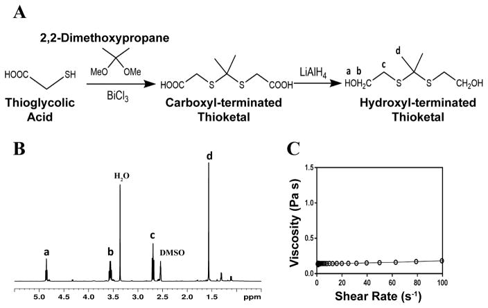
The schematic for thioketal diol synthesis is illustrated in Figure 1A. Bismuth (III) chloride was added to a dry boiling flask that was subsequently dried with a hot air gun under vacuum for about 5 minutes to ensure completely dry catalyst conditions. The flask was then purged with nitrogen and left under a positive pressure with nitrogen for the remainder of the reaction. Anhydrous acetonitrile was charged to the flask to dissolve the catalyst. 2,2-dimethoxypropane and thioglycolic acid were added to the flask, and the reaction was allowed to proceed for 24 hours while stirring at room temperature. The carboxyl-terminated intermediate was filtered with a Buchner funnel, rotary evaporated (Buchi Rotovap R-200, 35 °C), and dried under vacuum overnight. The carboxyl groups were then reduced to produce a hydroxyl-terminated TK. A 3-neck boiling flask was fitted to a 10 °C condenser capped with a 1-way glass stop-cock, a constant pressure dropping funnel, and a rubber stopper. The reactor was heated with a heat gun under vacuum for about 5 minutes to ensure completely dry reaction conditions. The reactor was then placed in an ice bath, purged with dry nitrogen, and maintained under positive pressure with nitrogen throughout the functionalization. Lithium aluminum hydride (LiAlH4) was added to the 3-neck boiling flask and dissolved in diethyl ether. Using anhydrous techniques, anhydrous tetrahydrofuran was added to the boiling flask containing the carboxyl-terminated TK. The resulting solution was then transferred to the dropping funnel and added to the LiAlH4 solution dropwise at 0 °C. After all of the TK solution was added, the ice bath was replaced with an oil bath and the reaction mixture was refluxed at 52°C for 6–8 hours. Unreacted LiAlH4 was quenched by adding DI water dropwise followed by 1M sodium hydroxide to aid in product extraction. By-products of the reaction were filtered using a Buchner funnel and filtration flask, and a separation funnel and diethyl ether were used to extract and isolate the TK diol product. The solvent was removed by rotary evaporation and the product dried under vacuum overnight for a completely dry, solvent-free TK diol. Nuclear magnetic resonance spectroscopy (1H NMR, Bruker 400 MHz NMR) in dimethylsulfoxide (DMSO) and attenuated total reflectance Fourier transform infrared spectroscopy (ATR-FTIR) verified the chemical structure of the TK diol. Titration of a sample reacted with excess p-toluenesulfonyl isocyanate with tetrabutylammonium hydroxide was used to determine the hydroxyl (OH) number of the TK diol according to ASTM E1899-08.24 The molecular weight (Mn) was calculated from the OH number using Eq (1):
| (1) |
Figure 1. Synthesis and characterization of low molecular weight thioketal diol.
(A) Synthesis scheme. (B) Characterization by NMR indicates that the targeted molecular structure was obtained. (C) Viscosity of the TK diol is independent of shear rate.
2.3 Quasi-prepolymer synthesis and characterization
A quasi-prepolymer was prepared according to methods previously described.25 Briefly, a 2.5:1 molar ratio of LTI:TK (3.75:1 NCO:OH equivalent ratio) was charged to a 100-mL boiling flask and purged with nitrogen while stirring in an oil bath at 45°C. TK diol was added to LTI drop-wise from a syringe through a 16G needle inserted through the rubber stopper. The reaction was allowed to proceed for 3 hours yielding an LTI-TK quasi-prepolymer. The NCO number was determined by titration according to ASTM D2572-97.26
2.4 Polyurethane/ceramic composite synthesis and characterization
PTKUR/ceramic composites were fabricated by reactive liquid molding and catalyzed using a 5% FeAA solution in ε-caprolactone. The isocyanate index (NCO:OH equivalent ratio * 100) was 140 for all materials.8 TK diol, LTI-TK prepolymer, and 55 wt% MG or 60 wt% nHA particles were hand-mixed to yield a reactive paste. These concentrations of the ceramic particles were selected as the maximum values that could be added while maintaining a cohesive reactive paste. Once homogeneous, 0.06 wt% FeAA (in solution) was added to catalyze the reaction between the LTI-TK prepolymer and the TK diol. The morphology of the composite was verified by scanning electron microscopy (Hitachi S4200 SEM) following gold sputter coating of thin sections of sample (Cressington Q108) for 45 seconds at 30 mA.
PTKUR films (without ceramic) synthesized using varying isocyanate indices were submerged in water for 2 weeks and water uptake measured periodically by weighing the samples. Swelling of films with indices of 110, 125, and 140 was calculated according to Eq (2), where Ms is the swollen mass and M0 is the initial mass. This information was used to determine effects of index on extent of crosslinking.
| (2) |
2.4.1 Reaction kinetics and working time
The reaction kinetics of the composite were assessed using methods described previously.8, 27 ATR-FTIR was used to evaluate the reaction rate of the isocyanate-terminated LTI-TK prepolymer with the other components of the composite individually by quantifying the disappearance of the isocyanate peak (around 2270 cm−1). The isocyanate peaks were calibrated to a standard curve of known NCO concentrations to find an initial rate constant for each reaction during the first 6 minutes. These rate constants along with the initial concentrations of each component were input into a Matlab program to calculate the number of isocyanate and hydroxyl equivalents versus time assuming second-order chemical kinetics. Isocyanate and hydroxyl conversion versus time were determined from the calculated numbers of equivalents.
The working time for the MG composites was defined using a rheometer with 25-mm plates. A gap size of 1.5 mm and constant strain (1%) and frequency (1 Hz) were applied to the composite and the working time defined by the time of the G′ – G″ crossover point. This time was compared to the tack-free time which was defined as when the material no longer stuck to a metal spatula.7
2.4.2 Compressive mechanical properties
Samples for compressive studies were prepared by injecting composites into 6 mm diameter tubes and compressing under a 0.96 kg weight to ensure cohesion throughout initial cure.28 Samples were cut to a height equal to 2 times their diameter (12 mm) using a Buehler IsoMet Low Speed Saw (Lake Bluff, Il). Modulus and strength were measured at various time points over a 2-week period to determine when the composites were completely crosslinked. Specimens were preloaded to 12 N and compressed at a rate of 25 mm min−1 using an MTS 858 Bionix Servohydraulic Test System (Eden Prairie, MN). The engineering stress was calculated by dividing the load by the platen-contacting surface area and the engineering strain determined by dividing the displacement by initial sample height. The slope of the linear-elastic portion of the resulting stress-strain curve was identified as the compressive modulus and the maximum stress as the compressive strength. When a maximum stress could not be identified, the stress at 10% strain was reported.29
2.4.3 Degradation
The degradation characteristics of PTKUR were assessed in hydrolytic and oxidative conditions. An accelerated degradation medium comprising 20 wt% hydrogen peroxide in 0.1 M cobalt chloride in DI water simulated the environment produced by reactive oxygen species at the implant site.20, 30, 31 PTKUR films (17 mg) were immersed in 350 μL (1 mL/50 mg initial sample) degradation media and placed on a shaker table at 37°C. PTKUR degradation was compared to lysine-derived poly(caprolactone urethane) (PCLUR), which was expected to undergo minimal hydrolytic degradation. Oxidative media was changed every 72 hours when time points exceeded 3 days to ensure the presence of oxidizing radicals. Samples were washed 3X with 100 mL DI water, dried under vacuum for at least 48 hours, and weighed at various time points to determine the degradation rate. Samples were gold sputter-coated for 45 seconds and imaged using SEM to visualize the change in architecture with degradation.
2.5 Rheology
Viscosity was characterized using a TA Instruments AR 2000ex rheometer fitted with 25-mm parallel plates at 25 °C. For the starting materials (TK diol and LTI-TK prepolymer), a small sample was injected between the plates which were subsequently depressed to a gap size of 500 μm. A frequency sweep was applied at a constant strain in the linear viscoelastic region (0.2 for the TK diol and 0.5 for the quasi prepolymer). A Cox-Merz transformation related the dynamic data to viscosity as a function of shear rate. The rheological properties of uncatalyzed (non-reactive) composites were found using a gap size of 1.5 mm. A constant strain of 1% was applied to the composite through a frequency sweep and a Cox-Merz transformation applied to characterize injectability.
2.6 In vitro characterization
The surface chemistry of PTKUR polymer films was observed by water contact angle using a Ramé-Hart Goniometer (Mountain Lakes, NJ) to predict cellular behavior at the material interface. Cellular attachment was verified using SEM and proliferation was observed using a BCA Protein Assay kit. MC3T3 cells were seeded (2 × 10⁴ cells/mL) onto thin sections of MG and nHA composites that were conditioned in complete αMEM medium with 10% FBS and 1% P/S overnight. Samples were submerged in 5% glutaraldehyde followed by 2% osmium tetroxide and an ethanol dehydration ladder to fix for SEM after 24 hours incubation. To measure proliferation, samples were taken from culture at 1, 4, and 7 days. Samples were transferred to a new well, washed with PBS, and the cells trypsinized. Cell pellets were lysed using RIPA buffer to extract the cellular protein. The BCA kit was used to quantify total protein at each time point.32
2.7 Implantation of PTKUR/ceramic composite cements in rabbits
Animal experiments were performed in compliance with relevant laws and the guidelines of IBEX Preclinical Research, Inc. (Logan, UT). The animal protocol was approved by the Institutional Animal Care and Use Committee (IACUC) at IBEX Preclinical Research, and all surgical and care procedures were carried out under aseptic conditions per the approved IACUC protocol. PTKUR/ceramic composites were evaluated in cylindrical femoral condyle plug defects in eight New Zealand White rabbits weighing 4–5 kg. The reactive components (TK diol, FeAA catalyst, LTI-TK prepolymer, MasterGraft, and nHA) were gamma-irradiated using a dose of approximately 25 kGY prior to use. After administration of anesthesia, bilateral defects 6–8 mm deep × 5 mm diameter were drilled in the femoral condyle of the distal femurs of 8 rabbits. PTKUR/ceramic composites incorporating either MG or nHA (n=3) were mixed on site, injected into the defect, and allowed to cure for 10 minutes prior to closing the wound. Animals were euthanized and femurs harvested at 6 and 12 weeks to evaluate healing and polymer degradation. Micro-computed tomography (Scanco μCT 50) was performed with a voxel size of 17.2 μm and a threshold of 237 (386 mg HA/cm3) to match the intensity of the native trabecular bone surrounding the defect. Histology preparation was performed by Histion. Calcified samples were embedded in PMMA and sections taken from the center of the defect area; the sections were stained with Stevenel’s Blue or hematoxylin and eosin (H&E) to identify new bone formation and cellular activity at the defect site.
2.8 Statistical analysis
Anova with post hoc comparisons using Tukey’s multiple comparisons test was applied to compression testing data to compare statistical differences with cure time. The Holm-Sidak multiple comparison test was used to evaluate significance in total protein over time for each composite individually, and the plot shows standard error of the mean (SEM). All other data was plotted with standard deviation, and p < 0.05 was considered statistically significant.
3. Results and Discussion
3.1 Thioketal diol and quasi-prepolymer characterization
The TK diol was synthesized following the two-step reaction scheme in Figure 1A. The characteristic NMR peak for the methyl (1.59 ppm) and hydroxyl (4.8 ppm) groups of the TK diol indicate that the targeted product was achieved (Figure 1B), and an ATR-FTIR absorbance peak around 3400 cm−1 confirmed hydroxyl functionalization.20 The OH number was found to be 574 mg KOH/g, which corresponds to a molecular weight of 196 g mol−1 (Eq 1). These data confirm that the desired product with a theoretical molecular weight of 196.3 g mol−1 was achieved. This low-molecular weight TK diol had a viscosity of 0.11 Pa s at a shear rate of 5 s−1 and exhibited near Newtonian behavior at shear rates below 100 s−1 (Figure 1C).
A quasi-prepolymer was synthesized to improve handling by increasing LTI viscosity, lowering the reaction exotherm, and minimizing phase separation during polymerization. TK diol was reacted with a 2.5 molar excess of LTI to form an LTI-TK prepolymer (Figure 2A). The excess of LTI greater than 2 renders this component a quasi-prepolymer, although it will be referred to as a prepolymer in this study.33 The LTI-TK prepolymer exhibited Newtonian behavior, but the viscosity of 61 Pa s (measured at 5 s−1, Figure 2B) was considerably greater than that measured for TK diol or LTI (0.036 – 0.061 Pa s).25 The %NCO number of the prepolymer determined by titration was 25.1%, which is slightly lower than the theoretical NCO number of 26.7% based on stoichiometry.
Figure 2. Synthesis of poly(thioketal urethane) (PTKUR)/ceramic composites.
(A) Synthesis scheme for LTI-TK prepolymer. (B) Viscosity of the LTI-TK prepolymer is independent of shear rate. (C) Reaction of TK diol with LTI-TK prepolymer to form a crosslinked PTKUR network. (D) Fabrication of PTKUR/ceramic composites by mixing LTI-TK prepolymer, TK diol, and ceramic particles (MG or nHA). (E) The viscosity of uncatalyzed (non-reactive) LTI-TK/TK diol/ceramic mixtures decreases with increasing shear rate, providing evidence of shear-thinning behavior. (F–G) SEM images of (F) MG and (G) nHA composites show lack of porosity. Due to their relatively large size (100 – 300 μm), MG particles (light grey and labeled MG) can be distinguished from the PTKUR phase (dark grey).
3.2 Composite characterization
Crosslinked PTKUR composites (Figure 2C) incorporating either MG or nHA particles were fabricated according to the schematic in Figure 2D. Figure 2E shows the initial (e.g., uncatalyzed) dynamic viscosities of both MG and nHA composites up to shear rates of 100 s−1. Both materials exhibit shear thinning behavior that is more prominent at lower shear rates, which enhances injectability, and have viscosities of 20–25 Pa s at a shear rate of 100 s−1. SEM images of the composites showed minimal porosity was achieved using a low-toxicity, iron-based gelling catalyst (25:1 gel:blow, Figure 2F–G) compared to previously investigated amine-based catalysts with high blowing power (1:20 gel:blow).10, 13, 23, 34
PTKUR films were made by mixing TK and LTI-TK prepolymer with iron catalyst without incorporating ceramic particles. The polymer film exhibited a contact angle of 70.2° indicating a moderately hydrophobic surface. Films of indices 110, 125, and 140 all swelled less than 3.5% after soaking in water for 2 weeks and the differences between them were not significant. Since there was no difference in swelling and the swelling was less than 5% for all samples, all of the indices were considered suitable for use in vivo. An index of 140 was chosen for the studies in this work to ensure complete crosslinking and a more rigid composite as reported previously.8, 28, 35
The reactivity of the polymer was investigated using ATR-FTIR. The second-order rate constant (ki, Eq (3)) of each component was calculated based on the initial isocyanate concentration (C0) and the disappearance of the isocyanate peak (C).8, 36
| (3) |
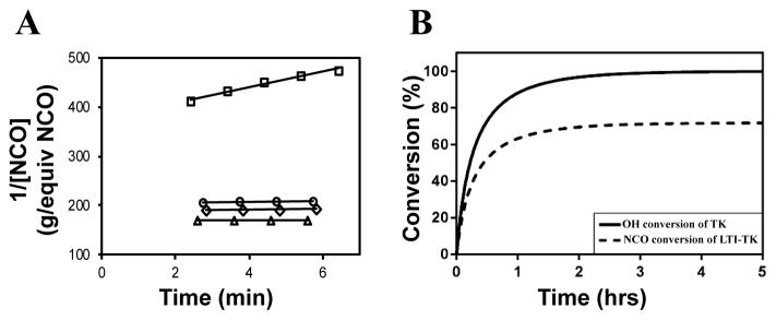
The catalyst was reduced by half (compared to the in vivo studies) for the reactivity experiments to slow the reaction, which was necessary to investigate the reaction mechanisms. Figure 3A shows the calculation of the initial rate constant (ki) for each reaction from the slope of the 2nd order rate plot, in which the inverse concentration of NCO equivalents (g / equiv NCO) is plotted versus time. The plot is linear for the first 6 minutes of the reaction, which confirms that the reactions are second order as anticipated.8, 36 Further, the very small slope for MG, nHA, and water with LTI-TK indicates these components have very low reactivity, and thus they were not included in the conversion calculations. The relatively high rate constant for the LTI-TK/TK gelling reaction compared to the LTI-TK/water blowing reaction (25:1 gel:blow ratio) confirms the preferential gelling activity of the iron acetylacetonate (FeAA) catalyst compared to the triethylene diamine (TEDA) catalyst investigated previously (1:20 gel:blow).8, 35 The concentration of LTI-TK prepolymer (I) and TK diol (D) were calculated as:
| (4) |
where Cj is the concentration of each component (I or D, g equiv−1 min−1) and M is the mass of the composite (g). The conversions of LTI-TK prepolymer and TK diol were calculated from the second-order kinetic model as:
| (5) |
Figure 3. Kinetics of the setting reaction.
(A) Second-order reaction kinetics plot of inverse NCO concentration (1/[NCO], g / equivalents NCO) versus time. The specific reaction rate (k) was calculated from the slope of the 1/[NCO] versus time plot, which is anticipated to be linear for second-order chemical reactions. The rate constant of the LTI-TK prepolymer-TK diol reaction (□) is substantially greater than that measured for MG (△), nHA (○), or water (⋄). (B) Using the rate constant for the dominant reaction TK diol + LTI-TK prepolymer and the second-order kinetics model, the conversions of the NCO and OH functional groups were calculated versus time.
Conversion of NCO and OH groups are shown in Figure 3B. The hydroxyl groups in the TK diol are completely converted and an excess of isocyanate functional groups remain, as anticipated from the high isocyanate index of 140. The excess isocyanate is anticipated to slowly react with the ceramic and environmental water, as reported previously for allograft bone composites9, due to the substantially lower reactivity of the LTI-TK prepolymer with these components. The tack-free time was determined by hand to be 6 minutes37 after mixing, which is comparable to the setting times for calcium phosphate cements. 2
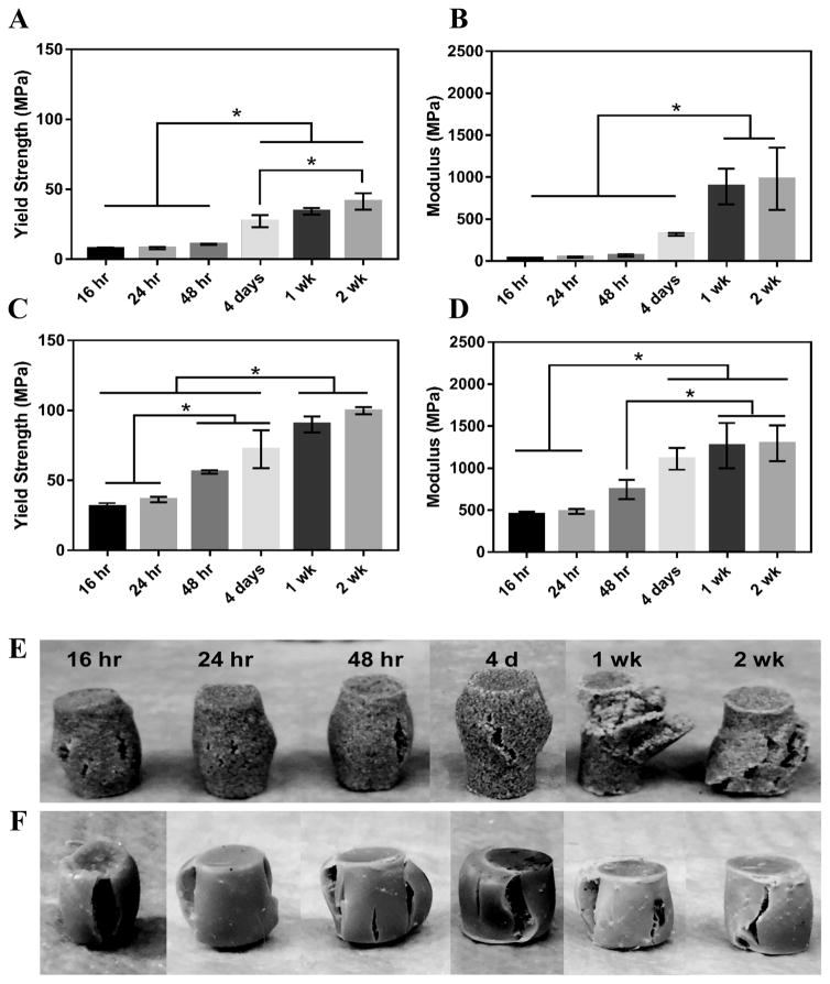
MG composites achieved a maximum compressive yield strength of 40 ± 7 MPa and modulus of 936 ± 46 MPa after 1 week of curing in air at RT (Figure 4A–B). These composites had an initial strength of 7.7 MPa and modulus of 36 MPa after 16 hours curing at RT. nHA composites exhibited initial strength and moduli much greater than MG composites as expected due to the increased surface area-to-volume ratio of the mechanically robust nanoparticles.38, 39 These cements had an initial compressive yield strength and modulus of 31 ± 3 MPa and 452 ± 35 MPa, respectively. The composites reached a yield strength of 90 ± 6 MPa and modulus of 1267 ± 277 MPa after 1 week (Figure 4C–D). The mechanical properties of both composites increased over the first week, indicating that complete crosslinking was achieved 1 week after fabrication. The physical appearance of the composites post-compression supports this finding. MG composites up to 48 hours cure time experience some elastic recovery to their original shape around 30 minutes post-compression, where plastic deformation is more evident in the 1 and 2 week samples (Figure 4E). These changes in resilience are less apparent in the stronger nHA samples (Figure 4F). Trabecular bone is reported to have a compressive strength of 5–10 MPa and modulus of 50–400 MPa.40–42 Therefore, the initial compressive strength and modulus of MG composites are close to the properties of trabecular bone and nHA composites exceed these properties. Both composites are mechanically stronger than trabecular bone after 1 week.
Figure 4.
Mechanical properties of PTKUR/ceramic composites under static compressive loading. (A) Yield strength and (B) modulus of PTKUR/MG composites measured versus time for up to two weeks. (C) Yield strength and (D) modulus of PTKUR/nHA composites measured versus time for up to two weeks. Maximum compressive properties were achieved after 1 week cure time. The physical appearance of (E) MG and (F) nHA composites after compressive testing supports this finding.
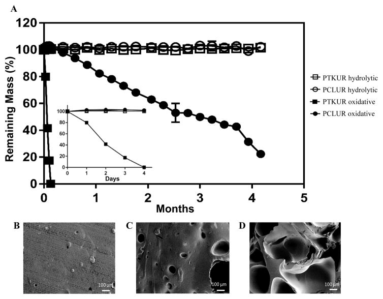
The degradation rate of PTKUR films under hydrolytic and oxidative conditions was measured in vitro. PTKUR was compared to PCLUR as this material has been shown to degrade slowly in vivo.5 PTKUR degraded completely after 4 days in vitro in oxidative media (Figure 5A inset) but experienced minimal hydrolytic degradation in PBS after 4 months (Figure 5A). SEM images of PTKUR after 24, 48, and 72 hours in oxidative media show morphological changes in the films in response to degradation, as evidenced by the formation of pores in the material (Figure 5B–D). PCLUR degraded minimally in PBS as expected and did not completely degrade in oxidative media until about 5 months.
Figure 5. Degradation of PCLUR and PTKUR films.
(A) PTKUR and PCLUR films were incubated in hydrolytic (open symbols) or oxidative (closed symbols). After 4 months, PCLUR and PTKUR films substantially degraded in oxidative medium, while no degradation was observed in hydrolytic medium. Furthermore, PKTUR films degraded after only 4 days incubation time in oxidative medium (inset). (B–D) SEM images show the effects of oxidative degradation on the architecture of the PTKUR films after (B) 24 h, (C) 48 h, and (D) 72 h.
3.3 In vitro characterization
The osteoblast precursor MC3T3 cell line was used in all in vitro studies to assess cell attachment and proliferation. SEM images show that cells attached and spread on MG (Figure 6A) and nHA (Figure 6B) composites after 24 h culture. Cell proliferation on the films was assessed for up to 7 days post-seeding by measuring the change in total protein with time. Figure 6C shows that the cell population on MG composites increased with time, but the differences were not significant. Cells proliferated on nHA composites, as evidenced by the increase in total protein from day 1 to day 7. Hydroxyapatite is the primary mineral component in bone, and therefore MC3T3 cells were expected to adhere and proliferate on scaffolds comprising 60 wt% nHA.43 While MG contains only 15% HA, the beta-tricalcium phosphate (β-TCP) component is also an osteoconductive ceramic.44, 45 The slower proliferation rate of MC3T3 cells on MG composites could potentially be explained by the relatively large size (100 – 300 μm) of the MG microparticles, resulting in relatively large areas of polymer that is less osteoconductive than the ceramic. In contrast, phase-separation of the nHA and polymer components was not observed in the nHA composites, suggesting that the nHA is more uniformly distributed due to its smaller particle size.
Figure 6.
MC3T3 cells (arrows) attached and spread on (A) MG and (B) nHA composites after 24 h incubation. Scale bar = 50 μm. (C) Measurements of total protein versus time indicate that cells proliferated faster on nHA composites.
3.4 Tissue and cellular response in the femoral condyle defect model
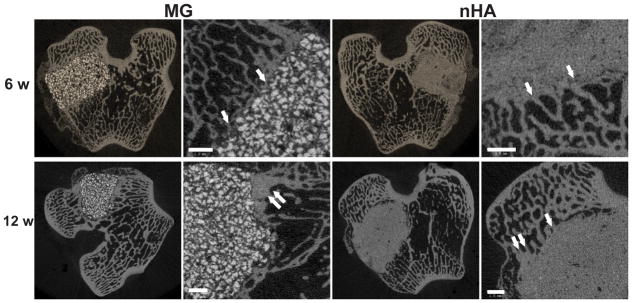
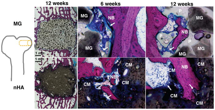
The composites were injected into femoral condyle plug defects in rabbits to assess bone healing and cement resorption. In vivo x-ray imaging immediately following the surgery indicated good placement and complete fill of the defect with the materials. μCT images of MG and nHA cements at 6 and 12 weeks are shown in Figure 7. Trabecular densification was evident at the periphery of the defects, indicating that the material was integrated with the host bone and initiating a healing response. Low-magnification (2X) images of histological sections stained with Stevenel’s Blue stain show appositional growth of dense trabecular bone near the host bone-cement interface at 12 weeks (Figure 8). The materials were well-tolerated by the host tissue and no adverse reactions were evident. Higher magnification (20–40X) images show remodeling and integration of the cements with host bone near the surface of the cements at 6 and 12 weeks. Due to the relatively large size of MG particles (100 – 300 μm), the PKTUR (P) and MG particles (MG) could be distinguished in the histological sections. PTKUR resorption near the interface was observed, resulting in cellular infiltration and new bone (NB, red) formation. Osteoid (arrows) was observed near the surface of the residual PTKUR. While the nHA particles were too small to distinguish in the histological sections, similar phenomena were observed for nHA cements. Resorption of the cement (CM) near the host bone interface resulted in new bone formation and osteoid was evident near the surface of the cement.
Figure 7. Images of transverse μCT sections of PTKUR/MG and PTKUR/nHA composite cements explanted at 6 and 12 weeks.
Higher magnification images of the defect periphery show evidence of trabecular infiltration (single white arrows) and trabecular densification (double white arrows). Scale bar = 1 mm.
Figure 8. Images of transverse histological sections of PTKUR/MG and PTKUR/nHA composite cements.
Low-magnification (2X) images of cements at 12 weeks show appositional growth of dense trabecular bone near the host bone-cement interface. Higher magnification (20–40X) images of PTKUR/MG cements at 6 and 12 weeks reveal evidence of residual MG (dark grey) particles, resorption of PTKUR (P, light grey), cellular infiltration (blue), osteoid (arrows), and new bone (NB, red) formation. Similar observations were made for PTKUR/nHA cements, but the nHA particles could not be distinguished due to their small size. Resorption of the cement (CM) was evident in the histological sections.
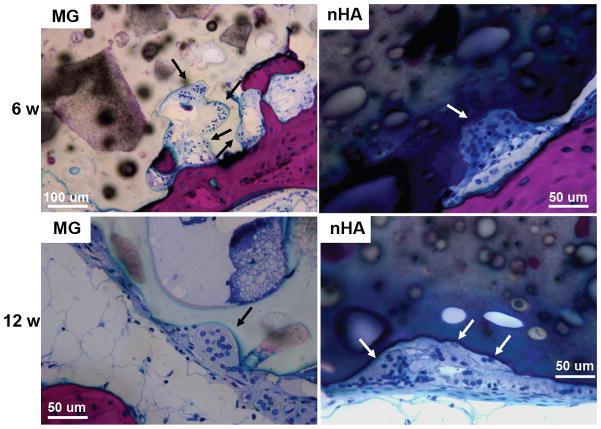
Resorption appeared to be cell-mediated, as indicated by the irregular morphology of the cement (black arrows, Figure 9) and the presence of osteoclast-like cells, identified as large (>50 μm) multi-nucleated (nuclei stained dark blue, Figure 9) cells, near the bone-cement interface. In contrast, negligible degradation was observed in the interior of the cement. These findings are consistent with the notion that resorption of the cements was surface-mediated by osteoclasts and/or macrophages through an ROS mechanism (Figure 5) as we have reported previously for PTKUR scaffolds implanted in cutaneous wounds.20 Due to their relatively large size (100–300 μm), MG particles can be observed in the SEM images as a distinct phase (“MG”, Figure 2F). Since osteoclasts are smaller than MG particles, resorption of the MG and PTKUR phases is anticipated to proceed at different rates. In contrast, the smaller nHA particles (100 nm) cannot be distinguished from the PTKUR component (Figure 2G). At the length scale of an osteoclast, the nHA composites comprise a single phase and are anticipated to resorb at a rate averaged over the resorption rates of the individual nHA and PTKUR components. Thus, differences in MG and nHA particle size may affect graft resorption. Due to the low (<10%) porosity of the cements, the rate of cellular infiltration and remodeling was slow. Increasing the porosity would be anticipated to accelerate infiltration of cells and consequent new bone formation.4
Figure 9. Resorption of PTKUR/MG and PTKUR/nHA cements mediated by osteoclast-like cells at 6 and 12 weeks.
Osteoclasts are identified as large (>50 μm) multi-nucleated (nucleus stains dark blue) cells near the host bone-cement interface.
4. Conclusion
In this study, a novel low-molecular weight thioketal diol crosslinker was synthesized to prepare cell-degradable bone cements with initial bone-like strength. The cements exhibited initial compressive strength exceeding that of trabecular bone, working times comparable to commercial bone cements (5 – 10 min), and degradation in response to reactive oxygen species secreted by cells. When implanted into femoral condyle plug defects in rabbits, the cements supported appositional new bone growth, osteoclast-mediated resorption, and integration with host bone. These findings highlight the potential of poly(thioketal urethane)/ceramic composite bone cements for repair of bone damaged by trauma or disease.
Supplementary Material
Acknowledgments
The authors acknowledge Dr. Mike Larson and his team at IBEX Preclinical Research, Inc. for performing the rabbit surgeries and providing post-operative care. This research was supported in part by an appointment to the Student Research Participation Program at the U.S. Army Medical Research and Materiel Command administered by the Oak Ridge Institute for Science and Education through an interagency agreement between the U.S. Department of Energy and USAMRMC. This work was also supported by the National Institutes of Health under award numbers R01AR064304 and R01EB019409 and the National Science Foundation Graduate Research Fellowship Program under Grant No. 1445197. The rabbit study was funded by Medtronic Spinal and Biologics. Any opinions, findings, and conclusions or recommendations expressed in this material are those of the author(s) and do not necessarily reflect the views of the National Institutes of Health or the National Science Foundation.
References
- 1.Kühn K-D. Bone cements: up-to-date comparison of physical and chemical properties of commercial materials. Springer; 2000. [Google Scholar]
- 2.Bohner M. Eur Cell Mater. 2010;20:3–10. doi: 10.22203/ecm.v020a01. [DOI] [PubMed] [Google Scholar]
- 3.Wagoner Johnson AJ, Herschler BA. Acta Biomaterialia. 2011;7:16–30. doi: 10.1016/j.actbio.2010.07.012. [DOI] [PubMed] [Google Scholar]
- 4.Adhikari R, Gunatillake PA, Griffiths I, Tatai L, Wickramaratna M, Houshyar S, Moore T, Mayadunne RT, Field J, McGee M, Carbon T. Biomaterials. 2008;29:3762–3770. doi: 10.1016/j.biomaterials.2008.06.021. [DOI] [PubMed] [Google Scholar]
- 5.Dumas JE, Davis T, Holt GE, Yoshii T, Perrien DS, Nyman JS, Boyce T, Guelcher SA. Acta Biomaterialia. 2010;6:2394–2406. doi: 10.1016/j.actbio.2010.01.030. [DOI] [PubMed] [Google Scholar]
- 6.Bonzani IC, Adhikari R, Houshyar S, Mayadunne R, Gunatillake P, Stevens MM. Biomaterials. 2007;28:423–433. doi: 10.1016/j.biomaterials.2006.08.026. [DOI] [PubMed] [Google Scholar]
- 7.Dumas JE, Zienkiewicz K, Tanner SA, Prieto EM, Bhattacharyya S, Guelcher SA. Tissue Engineering Part A. 2010;16:2505–2518. doi: 10.1089/ten.TEA.2009.0672. [DOI] [PubMed] [Google Scholar]
- 8.Page JM, Prieto EM, Dumas JE, Zienkiewicz KJ, Wenke JC, Brown-Baer P, Guelcher SA. Acta biomaterialia. 2012;8:4405–4416. doi: 10.1016/j.actbio.2012.07.037. [DOI] [PubMed] [Google Scholar]
- 9.Dumas JE, Prieto EM, Zienkiewicz KJ, Guda T, Wenke JC, Bible J, Holt GE, Guelcher SA. Tissue Engineering Part A. 2014;20:115–129. doi: 10.1089/ten.tea.2012.0762. [DOI] [PMC free article] [PubMed] [Google Scholar]
- 10.Hafeman AE, Zienkiewicz KJ, Zachman AL, Sung H-J, Nanney LB, Davidson JM, Guelcher SA. Biomaterials. 2011;32:419–429. doi: 10.1016/j.biomaterials.2010.08.108. [DOI] [PMC free article] [PubMed] [Google Scholar]
- 11.de Bruyn PP, Kabisch WT. American Journal of Anatomy. 1955;96:375–417. doi: 10.1002/aja.1000960304. [DOI] [PubMed] [Google Scholar]
- 12.Dumas JE, BrownBaer PB, Prieto EM, Guda T, Hale RG, Wenke JC, Guelcher SA. Biomedical Materials. 2012;7:024112. doi: 10.1088/1748-6041/7/2/024112. [DOI] [PubMed] [Google Scholar]
- 13.Prieto EM, Talley AD, Gould NR, Zienkiewicz KJ, Drapeau SJ, Kalpakci KN, Guelcher SA. Journal of biomedical materials research Part B, Applied biomaterials. 2015 doi: 10.1002/jbm.b.33349. [DOI] [PMC free article] [PubMed] [Google Scholar]
- 14.Loi F, Córdova LA, Pajarinen J, Lin T-h, Yao Z, Goodman SB. Bone. 2016;86:119–130. doi: 10.1016/j.bone.2016.02.020. [DOI] [PMC free article] [PubMed] [Google Scholar]
- 15.Schmidt-Bleek K, Kwee BJ, Mooney DJ, Duda GN. Tissue Engineering Part B: Reviews. 2015;21:354–364. doi: 10.1089/ten.teb.2014.0677. [DOI] [PMC free article] [PubMed] [Google Scholar]
- 16.Nukavarapu S, Freeman J, Laurencin C. Regenerative Engineering of Musculoskeletal Tissues and Interfaces. Woodhead Publishing; 2015. [Google Scholar]
- 17.Sheweita SA, Khoshhal KI, Baghdadi HH. Systems Biology of Free Radicals and Antioxidants. Springer; 2014. pp. 2973–2995. [Google Scholar]
- 18.Garrett I, Boyce B, Oreffo R, Bonewald L, Poser J, Mundy G. Journal of Clinical Investigation. 1990;85:632. doi: 10.1172/JCI114485. [DOI] [PMC free article] [PubMed] [Google Scholar]
- 19.Key LL, Wolf WC, Gundberg CM, Ries WL. Bone. 1994;15:431–436. doi: 10.1016/8756-3282(94)90821-4. [DOI] [PubMed] [Google Scholar]
- 20.Martin JR, Gupta MK, Page JM, Yu F, Davidson JM, Guelcher SA, Duvall CL. Biomaterials. 2014;35:3766–3776. doi: 10.1016/j.biomaterials.2014.01.026. [DOI] [PMC free article] [PubMed] [Google Scholar]
- 21.Wilson DS, Dalmasso G, Wang L, Sitaraman SV, Merlin D, Murthy N. Nat Mater. 2010;9:923–928. doi: 10.1038/nmat2859. [DOI] [PMC free article] [PubMed] [Google Scholar]
- 22.LeGeros RZ. Clinical orthopaedics and related research. 2002;395:81–98. doi: 10.1097/00003086-200202000-00009. [DOI] [PubMed] [Google Scholar]
- 23.Talley AD, Mcenery MAP, Kalpakci KN, Zienkiewicz KJ, Shimko DA, Guelcher SA. Journal of Biomedical Materials Research Part B: Applied Biomaterials. 2016 doi: 10.1002/jbm.b.33767. in press. [DOI] [PubMed] [Google Scholar]
- 24.A International, Journal. 2016:E1899–16. [Google Scholar]
- 25.Guelcher SA, Srinivasan A, Dumas JE, Didier JE, McBride S, Hollinger JO. Biomaterials. 2008;29:1762–1775. doi: 10.1016/j.biomaterials.2007.12.046. [DOI] [PubMed] [Google Scholar]
- 26.A International, Journal. 2010 [Google Scholar]
- 27.Guo R, Ward CL, Davidson JM, Duvall CL, Wenke JC, Guelcher SA. Biomaterials. 2015;54:21–33. doi: 10.1016/j.biomaterials.2015.03.010. [DOI] [PMC free article] [PubMed] [Google Scholar]
- 28.Harmata AJ, Uppuganti S, Granke M, Guelcher SA, Nyman JS. Journal of the mechanical behavior of biomedical materials. 2015;51:345–355. doi: 10.1016/j.jmbbm.2015.07.027. [DOI] [PMC free article] [PubMed] [Google Scholar]
- 29.A International, Journal. 2016 [Google Scholar]
- 30.Schubert MA, Wiggins MJ, Anderson JM, Hiltner A. Journal of Biomedical Materials Research. 1997;34:519–530. doi: 10.1002/(sici)1097-4636(19970315)34:4<519::aid-jbm12>3.0.co;2-7. [DOI] [PubMed] [Google Scholar]
- 31.Christenson EM, Anderson JM, Hiltner A. Journal of Biomedical Materials Research Part A. 2004;70A:245–255. doi: 10.1002/jbm.a.30067. [DOI] [PubMed] [Google Scholar]
- 32.Guo R, Lu S, Page JM, Merkel AR, Basu S, Sterling JA, Guelcher SA. Advanced healthcare materials. 2015;4:1826–1832. doi: 10.1002/adhm.201500099. [DOI] [PMC free article] [PubMed] [Google Scholar]
- 33. [accessed 05/23/2016, 2016];Dow polyurethanes - prepolymer definition. http://dowac.custhelp.com/app/answers/detail/a_id/5082/~/dow-polyurethanes---prepolymer-definition.
- 34.Guelcher SA, Patel V, Gallagher KM, Connolly S, Didier JE, Doctor JS, Hollinger JO. Tissue Engineering. 2006;12:1247–1259. doi: 10.1089/ten.2006.12.1247. [DOI] [PubMed] [Google Scholar]
- 35.Harmata AJ, Ward CL, Zienkiewicz KJ, Wenke JC, Guelcher SA. Journal of Materials Research. 2014;29:2398–2407. doi: 10.1557/jmr.2014.254. [DOI] [PMC free article] [PubMed] [Google Scholar]
- 36.Parnell S, Min K, Cakmak M. Polymer. 2003;44:5137–5144. [Google Scholar]
- 37.Ashida K. Polyurethane and related foams: chemistry and technology. CRC press; 2006. [Google Scholar]
- 38.Mi H-Y, Jing X, Salick MR, Cordie TM, Peng X-F, Turng L-S. Journal of Materials Science. 2014;49:2324–2337. [Google Scholar]
- 39.Rezwan K, Chen Q, Blaker J, Boccaccini AR. Biomaterials. 2006;27:3413–3431. doi: 10.1016/j.biomaterials.2006.01.039. [DOI] [PubMed] [Google Scholar]
- 40.Fernando S, McEnery M, Guelcher S. Advances in Polyurethane Biomaterials. 2016:481. [Google Scholar]
- 41.Karageorgiou V, Kaplan D. Biomaterials. 2005;26:5474–5491. doi: 10.1016/j.biomaterials.2005.02.002. [DOI] [PubMed] [Google Scholar]
- 42.Muggli DS, Burkoth AK, Anseth KS. Journal of biomedical materials research. 1999;46:271–278. doi: 10.1002/(sici)1097-4636(199908)46:2<271::aid-jbm17>3.0.co;2-x. [DOI] [PubMed] [Google Scholar]
- 43.Buckwalter J, Glimcher M, Cooper R, Recker R. J Bone Joint Surg Am. 1995;77:1256–1275. [Google Scholar]
- 44.Gaasbeek RDA, Toonen HG, van Heerwaarden RJ, Buma P. Biomaterials. 2005;26:6713–6719. doi: 10.1016/j.biomaterials.2005.04.056. [DOI] [PubMed] [Google Scholar]
- 45.Giannoudis PV, Dinopoulos H, Tsiridis E. Injury. 2005;36:S20–S27. doi: 10.1016/j.injury.2005.07.029. [DOI] [PubMed] [Google Scholar]
Associated Data
This section collects any data citations, data availability statements, or supplementary materials included in this article.


