Abstract
Objective:
There is no consensus approach to covering skull base meningeal reflections—and cerebrospinal fluid (CSF) therein—of the posterior fossa cranial nerves (CNs VII–XII) when planning radiotherapy (RT) for medulloblastoma and ependymoma. We sought to determine whether MRI and specifically fast imaging employing steady-state acquisition (FIESTA) sequences can answer this anatomical question and guide RT planning.
Methods:
96 posterior fossa FIESTA sequences were reviewed. Following exclusions, measurements were made on the following scans for each foramen respectively (left, right); internal acoustic meatus (IAM) (86, 84), jugular foramen (JF) (83, 85) and hypoglossal canal (HC) (42, 45). A protocol describes measurement procedure. Two observers measured distances for five cases and agreement was assessed. One observer measured all the remaining cases.
Results:
IAM and JF measurement interobserver variability was compared. Mean measurement difference between observers was −0.275 mm (standard deviation 0.557). IAM and JF measurements were normally distributed. Mean IAM distance was 12.2 mm [95% confidence interval (CI) 8.8–15.6]; JF was 7.3 mm (95% CI 4.0–10.6). The HC was difficult to visualize on many images and data followed a bimodal distribution.
Conclusion:
Dural reflections of posterior fossa CNs are well demonstrated by FIESTA MRI. Measuring CSF extension into these structures is feasible and robust; mean CSF extension into IAM and JF was measured. We plan further work to assess coverage of these structures with photon and proton RT plans.
Advances in knowledge:
We have described CSF extension beyond the internal table of the skull into the IAM, JF and HC. Oncologists planning RT for patients with medulloblastoma and ependymoma may use these data to guide contouring.
INTRODUCTION
Clinical Setting
High-quality radiotherapy (RT) remains a crucial aspect of treatment for medulloblastoma and there are clear data linking inadequate technique to recurrence.1–5 These tumours arise infratentorially within the cerebellum or in the vicinity of the fourth ventricle. Their typical pattern of spread is to meningeal surfaces, frequently locoregionally in the posterior fossa.6,7 The RT approach reflects this biology and current “gold standard” involves irradiation of the entire craniospinal axis (CSI) with a boost to the posterior fossa and tumour bed. Ependymomas are rare tumours arising from glial cells (primary gliomas). In children, they tend to occur intracranially in the region of the fourth ventricle whereas in adults they are more frequently spinal. RT is used, but in contrast to medulloblastoma, it is usually delivered focally only to the tumour bed, depending on factors such as histological characteristics and extent of resection on post-operative MRI.8 Where it does occur, over 90% of recurrences are local.9–12 CSI is used only for confirmed cerebrospinal fluid (CSF) dissemination.13
Techniques for delivering CSI have evolved significantly over recent decades. The classical approach is to use parallel-opposed lateral cranial fields matched to a direct posterior field. The subsequent development of three-dimensional (3D) conformal and intensity-modulated RT has seen these solutions increasingly used to deliver CSI and boost the posterior fossa,14–17 and there is increasing interest in proton RT for both conditions, not least as reduced integral doses to normal structures may improve toxicity and second malignancy rates.18
Although minimizing toxicity is important, the primary treatment objective must remain cure. Studies report the risk of cribiform plate recurrence in patients undergoing CSI in the era before this was considered to be part of the target volume, or when it was underdosed owing to either inadequate technique or deliberate shielding of the eyes.4,19–21 The same technical errors also resulted in recurrences inferiorly in the frontal and temporal lobes,21 and there is now a general consensus that these structures should be included in the target volume however RT is planned and delivered.
An unresolved issue is the CSF contained within the dural reflections of the posterior fossa nerves [cranial nerves (CNs) VII–XII] as they exit their respective skull base foramen. We suspect that a conventional field-based CSI technique for medulloblastoma will adequately cover these structures and their meningeal surfaces.22 However, there is no consensus about how to approach this problem when planning volume-based RT, delivered with either photons or protons. A similar question is posed for ependymoma treatment and we suggest that the internal acoustic meatus (IAM), jugular foramen (JF) and hypoglossal canal (HC) may provide a breach in the natural barrier to local spread provided by the internal table of the skull.
The purpose of this study was therefore to investigate the anatomy of CSF extension into the IAM, JF and HC and specifically how far CSF travels down these structures and away from the natural line of the internal aspect of the skull and a putative clinical target volume (CTV).
MRI of posterior fossa cranial nerves
MRI has been used to assess the anatomy of the central nervous system and CSF for 30 years.23,24 Much work has gone into establishing the optimal protocol for imaging CNs. Sequences such as 3D Fourier transform and constructive interference in steady state have been used to investigate trigeminal neuralgia, hemifacial spasm and acoustic neuroma.25 Subsequent work concluded that the 3D constructive interference in steady state sequence (with a 1.5-T magnet) gave the best resolution for CNs surrounded by CSF.26 One of the difficulties of imaging CSF spaces with MRI is the artefact generated by natural fluid flow. Thus, techniques that reduce scanning time should give better image quality. Ciftci et al27 described the addition of a driven equilibrium radiofrequency reset pulse to a T2 weighted turbo spin-echo sequence. The driven equilibrium radiofrequency reset sequences provided better image quality and performed slightly better than the T2 weighted 3D turbo spin-echo sequences in identifying individual nerves. The scan times were also 25% shorter.
Fast imaging employing steady-state acquisition (FIESTA) MRI uses ultrashort repetition time and echo time to obtain very fast acquisition times. There is a high signal-to-noise ratio with strong signal from fluid and suppression of background tissue which gives good contrast and, importantly, anatomical details of small structures. One study looked to map the cisternal segments of CNs IX–XI, using 3D balanced fast-field echo imaging—the Phillips equivalent of FIESTA—to acquire detailed images of these structures and to measure both the length and angle of their intracisternal courses.28 They concluded that the quality of the images obtained permitted very detailed and accurate anatomical information to be recorded. More recently, CN imaging data from a 7.0-T magnet concluded that true-fast imaging with steady state precession sequences—another FIESTA equivalent—gave the best spatial resolution and contrast29 and FIESTA MRI has been successfully used to identify the glossopharyngeal nerve (CNIX), vagus nerve (CNX) and accessory nerve (CNXI) within the JF,30 although no measurements of CSF extension were made in this study. FIESTA images were therefore selected as the tool to address this anatomical question.
METHODS AND MATERIALS
This project was registered as a service evaluation (Proposal No. 193) with the Addenbrooke Cancer Division and Haematology Directorate and Audit Department and constituted part of an MSc thesis project with the Institute of Cancer Research. It was a retrospective analysis of images for service evaluation where all imaging had been performed for clinical purposes and no further ethical approval was required or sought.
Patients
An automated search of the Addenbrooke Radiology Department archive for patients undergoing MRI which included the word “FIESTA” was carried out. This produced 96 FIESTA MRI examinations of the posterior fossa. Patients were predominantly adults (median age 49 years, range 1–90 years). 10 patients in our study were under the age of 10 years, the remainder were adults. The three most common imaging indications were hearing loss (19%), hemifacial pain (19%) and headache (14%). A full list of indications (some patients had more than one) is given in Supplementary Figures and Tables.
Imaging
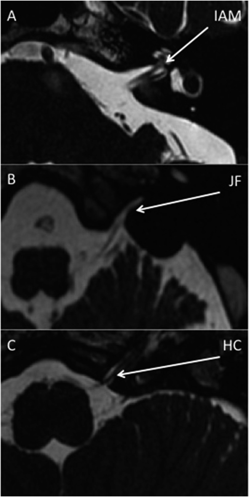
Imaging was performed on 1.5-T MR units (GE Signa Excite, GE Discovery MR450). Imaging parameters were repetition time 6.5 ms, echo time 1.05 ms, field of view 22 cm, slice thickness 0.8 mm, overlap 0.4 mm and matrix 256 × 256 pixels. Example FIESTA images demonstrating the IAM, JM and HC CSF and relevant CNs are shown in Figure 1. Examinations were excluded from analysis for the following reasons: abnormal anatomy, sagittal reconstructions only, poor image quality, limited number of slices and no FIESTA images available. This left the following number of scans for analysis for each foramen: 86 scans for left IAM, 84 scans for right IAM, 83 scans for left JF, 85 scans for right JF, 42 scans for left HC and 45 scans for right HC, respectively.
Figure 1.
Fast imaging employing steady-state acquisition MR images are showing cerebrospinal fluid and cranial nerves evaginating into the left internal acoustic meatus (IAM) (a), jugular foramen (JF) (b) and hypoglossal canal (HC) (c).
Measurement
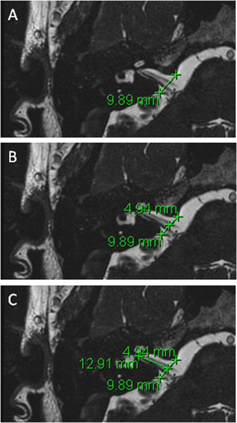
The procedure for measuring CSF extension into relevant foramen is described below, with a sample image shown in Figure 2.
By careful visual inspection, identify the axial slice with the furthest extension of CSF along the meatus.
Measure the distance between the most prominent bony landmarks on either side of the meatus (Figure 2a).
Measure half of that distance (Figure 2b).
Measure distance from this mid-point to the furthest CSF extent along the meatus (Figure 2c).
Figure 2.
An example of measurement protocol—measurement of cerebrospinal fluid into the right internal acoustic meatus.
This protocol was used by two independent observers to assess reproducibility of the measurements made. Both Observer 1 (a consultant neuroradiologist) and Observer 2 (a senior radiation oncology trainee) measured distances for the first five patients on the database. Measurements of the HC were excluded from analysis for reasons that will be described in results, leaving 20 data points for comparison. Observer 2 subsequently assessed the remaining 91 cases.
Statistics
Statistical analyses were performed using Microsoft Office Excel® 2010 (Microsoft, Redmond, WA). Interobserver variability was assessed with Pearson product moment coefficient and a Bland–Altman analysis.31 Data for the full cohort were plotted as histograms and described with mean values and standard deviation (SD).
RESULTS
Anatomy—agreement
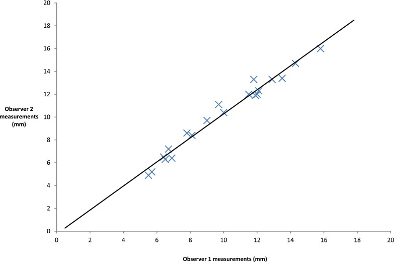
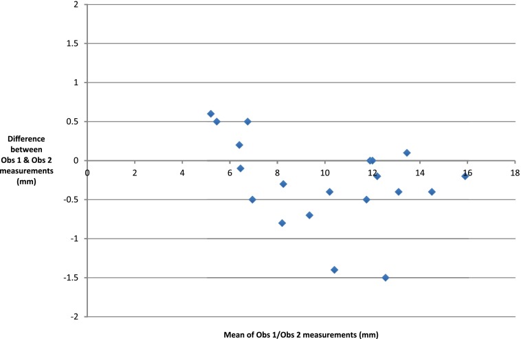
Interobserver data for the first five patients are shown in Table 1. There were only two data points where the two measurements differed by >1 mm. There appears to be good agreement. A scatter plot (Figure 3) shows excellent correlation (r = 0.987) but does not assess agreement; so, a Bland–Altman analysis was undertaken. The difference between each data point was first calculated and from this, both the mean difference and SD of those differences within the sample were computed (Supplementary Table A). Differences between measurements were then plotted against the mean measurement for each data point (Figure 4).
Table 1.
Observer 1 and Observer 2 measurements of internal acoustic meatus (IAM) and jugular foramen (JF)
| Case number | Observer 1 IAM (mm) | Observer 2 IAM (mm) | Observer 1 JF (mm) | Observer 2 JF (mm) |
|---|---|---|---|---|
| 1 Right | 13.5 | 13.4 | 9.7 | 11.1 |
| 2 Right | 12.1 | 12.3 | 6.7 | 7.2 |
| 3 Right | 12.9 | 13.3 | 6.9 | 6.4 |
| 4 Right | 7.8 | 8.6 | 5.7 | 5.2 |
| 5 Right | 14.3 | 14.7 | 11.9 | 11.9 |
| 1 Left | 11.5 | 12 | 10 | 10.4 |
| 2 Left | 11.8 | 13.3 | 6.5 | 6.3 |
| 3 Left | 12 | 12 | 6.4 | 6.5 |
| 4 Left | 8.1 | 8.4 | 5.5 | 4.9 |
| 5 Left | 15.8 | 16 | 9 | 9.7 |
Figure 3.
A scatter plot of internal acoustic meatus and jugular foramen measurements by the two observers.
Figure 4.
A scatter plot is showing differences between observations against mean measurement.
The mean of the differences (d) of Observer 1 measurements vs Observer 2 measurements was −0.275 mm and the SD of differences was 0.557. Further aspects of the Bland–Altman analysis depend upon the distribution of the differences between measurements. A histogram of these differences (Supplementary Figure A) demonstrates a convincing normal distribution, despite the small sample size.
If the assumption of normality is accepted, then 95% of the measurements would be expected to lie in a range described by the mean difference (bias) and 1.96 SDs either side of this;
−0.275 − (1.96 × 0.557) = −1.36.
−0.275 + (1.96 × 0.557) = 0.81.
This suggests that the limits of agreement for measuring the IAM and JF on FIESTA MR images with this protocol are from −1.36 to 0.81 mm. Therefore, 95% of the measurements made by the two independent observers using this technique were within 2.2 mm of each other.
Anatomy—internal acoustic meatus
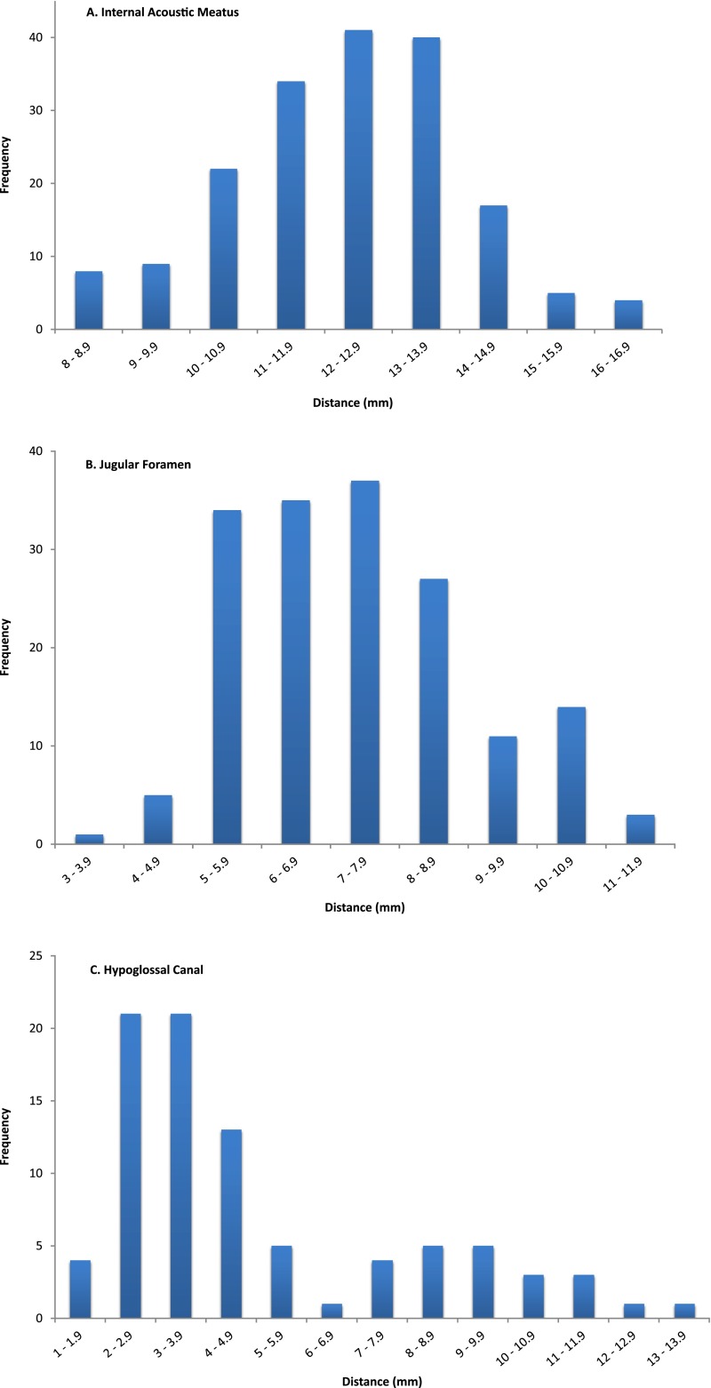
86 left and 84 right IAMs were measured, giving 170 measurements in total. The data were normally distributed (Figure 5a). The mean distance of CSF extension into the IAM was 12.2 mm; the SD was 1.75. It can therefore be inferred that in 95% of cases, CSF extension into this structure will be 12.2 ± (1.96 × 1.75) mm, i.e. 8.8–15.6 mm.
Figure 5.
Histograms are showing the distribution of cerebrospinal fluid extension into internal acoustic meatus (a), jugular foramen (b) and hypoglossal canal (c).
Anatomy—jugular foramen
83 left and 85 right JFs were analyzed, giving 168 measurements in total. A normal distribution was assumed (Figure 5b).The mean distance of CSF extension into the JF was 7.3 mm. The SD was 1.67. Using the same argument as seen for IAM, 7.3 ± (1.96 × 1.67) mm, it can be concluded that in this population, CSF extension into the JF will be between 4.0 and 10.6 mm in 95% of cases.
Anatomy—hypoglossal canal
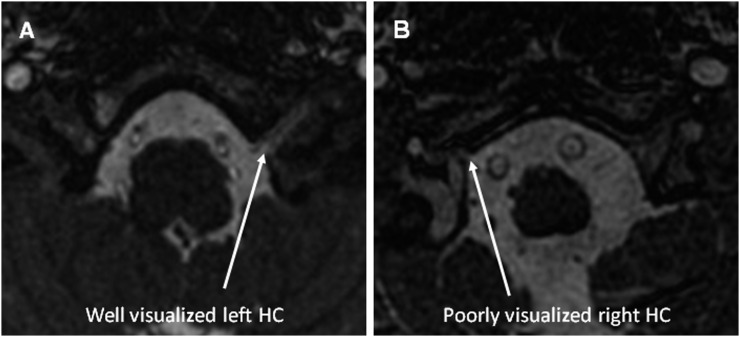
The HC was hard to identify and measure on many images. This was largely due to the structure being at the inferior extent of the scan. However, this was not universal and for some examinations, the structure was clearly visible with a crisp interface between the bone and CSF. An image of each circumstance is shown in Figure 6. 42 left and 45 right HCs were measured and the data were bimodally distributed (Figure 5c). The mean of these data is 4.9 mm, but given the distribution, this is meaningless. Taking data only from scans where the structure was clearly visible, we suggest that the “true” figure is in the region of 9–10 mm. This is a tentative conclusion and will be considered further in the discussion section.
Figure 6.
Examples of well (a) and poorly (b) visualized hypoglossal canals (HCs).
Relevance for radiotherapy planning
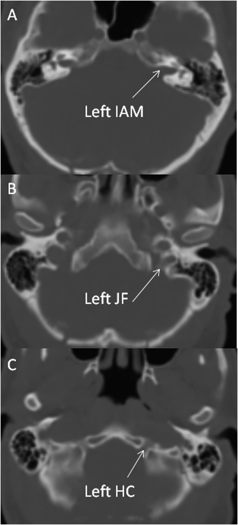
These data are relevant for oncologists planning both CSI and focal RT for ependymoma. Figure 7 is the RT planning CT of a patient who underwent CSI at our centre and demonstrates that these structures are well visualized on RT planning scans.
Figure 7.
Radiotherapy planning CT images are clearly showing the bony anatomy of the internal acoustic meatus (IAM) (a), jugular foramen (JF) (b) and hypoglossal canal (HC) (c).
DISCUSSION
MRI techniques have been shown to accurately identify and visualize CNs and their passage into respective foramen. The detail achievable allows the precise anatomy of CSF evaginating into Dorello's canal with the abducent nerve to be seen and measured.32 FIESTA MRI gives excellent images and permits detailed analysis of the cisternal segments of posterior fossa CNs.33–35 Our study is the first using FIESTA MRI to measure CSF extension into the dural cuffs of posterior fossa CNs as they exit the skull base. Interobserver variability shows good agreement, with 95% of measurements within 2.2 mm of each other. A Bland–Altman approach has been used to assess interobserver variability of MRI parameters across a range of conditions and anatomical regions as varied as head and neck cancer, evaluation of normal breast tissue and cerebral blood flow.36–38 To the best of our knowledge, it has not been used previously in this context. One group have quantified interobserver variability of cross-sectional measurements of the cochlear and facial nerves.39 They report correlation coefficients (0.974 and 0.987) very similar to that which we report (0.987), but did not measure agreement with a Bland–Altman analysis. We conclude that the method described gives an accurate assessment of meningeal and CSF extension into the relevant CN foramen.
The IAM data show that 97.5% of patients would be expected to have CSF extension into this structure no further than 15.6 mm from the internal table of the skull. It is known that the dura covers the bony surfaces of the IAM and that the neurovascular contents of this structure are surrounded by circulating CSF up to its fundus.40 It is therefore reasonable to suggest that the internal aspect of the bone wall of the canal provides an excellent surrogate for CSF and meningeal extension. As shown in Figure 7a, the bone wall of the IAM is well visualized on a RT planning CT, and the IAM should be specifically drawn as part of the CTV if all CSF and meningeal surfaces are to be included. Many RT planning software platforms permit fusion of the planning CT and MR images; accurate fusion in this context may facilitate precise measurement and optimize contouring.
For the JF, the mean distance is 7.3 mm (95% confidence interval 4.0–10.6). By similar logic, only 2.5% of people would be expected to have CSF extension into this structure beyond 10.6 mm. The JF has been described by one author as having three compartments; a neural compartment containing CNs IX–XI, a larger venous compartment containing the sigmoid sinus (sigmoid part) and a smaller petrosal part containing the inferior petrosal sinus (which drains the cavernous sinus into the internal jugular vein).41 Others describe a division into two parts by a fibrous or osseous bridge, with the anteromedial compartment, the pars nervosa, containing the glossopharyngeal nerve (IX) and the inferior petrosal sinus and the posterolateral pars vascularis containing the vagus (X) and accessory (XI) nerves and the jugular bulb.42
However, radiological and surgical cadaveric studies agree that the anatomy of the JF is complex and varies significantly between individuals.43–45 Thus, whilst CT images demonstrate the bony anatomy of the JF well,43,44 and as seen with the planning CT example in Figure 7b, these data may be extremely useful to an oncologist wishing to account for CSF in the structure and be guided as to the likely extent of CSF extension. Again, it also makes the more straightforward point that CSF is found beyond the internal table of the skull in the JF and should be contoured as part of the CTV if the intention is to treat all meninges and CSF.
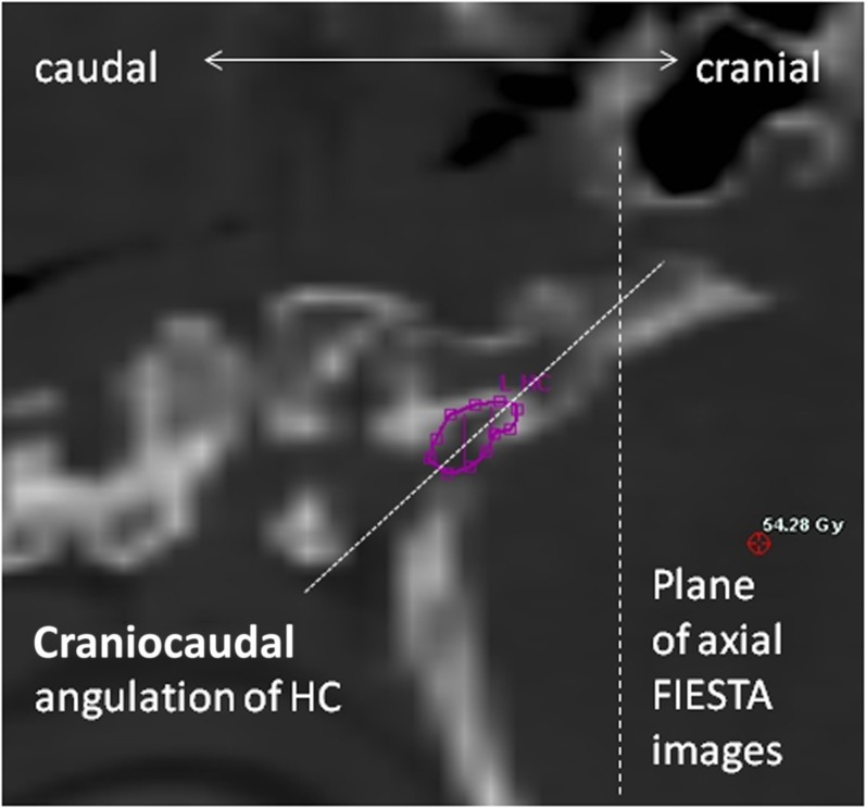
As described, fewer images permitted satisfactory measurement of the HC and the data that were generated are less clear. Other authors have successfully identified CN XII and the HC using MRI but concede that visualizing different segments of nerve segments depends upon using the right sequences.46–48 The main reason for the difficulty we found is that the HC was often at the inferior border of the scan and image quality was poor. Another possible reason is the angle at which slices of the structure were taken. Our impression, from the images reviewed in this study, is that the HC runs anterolaterally but also cranially across the occipital bone, as shown in Figure 8. This observation has not been quantified in our work, or elsewhere in the literature. If this assertion is true, a true axial image would not be parallel to the plane of the HC, which would therefore be harder to identify. However, as FIESTA is a 3D sequence with no gap, it would be possible to reconstruct imaging sequences with an adequate field of view in the oblique plane to better visualize this structure. It is also worth noting that the bony canal of the HC is well shown on a RT planning CT, as shown in Figure 7c.
Figure 8.
Sagittal reconstruction of a radiotherapy planning scan is showing steep caudocranial angulation of hypoglossal canal (HC). FIESTA, fast imaging employing steady-state acquisition.
The most apparent weakness of this study is the fact that the radiological data were derived from a predominantly adult population, whilst the tumour types of interest are most common in children. It is known that the head grows less over childhood than torso and limbs and that adult body proportions are brought about by differential growth of body segments.49 At birth, head length is a quarter of total body length; at 25 years of age, it is one-eighth.50 It must therefore be assumed that these structures in young children will be smaller than they are in adults, although precise ratios may be difficult to quantify. In many ways, however, this is reassuring as the CSF data presented may be a slight overestimate of the reality in a paediatric population. Provided the data are taken in context and interpreted correctly, they can still act as a useful guide when planning RT for paediatric cases.
This study has not addressed issues around how to manage CNs I–VI. It is reasonable to assume that the olfactory nerve will be contained within a CTV that includes the cribiform plate, and this has already been discussed.4,19–21 We know that the optic nerves are surrounded by CSF to the back of the globe and that some RT planning techniques (tomotherapy) underdose this area unless it is specifically contoured as part of the CTV.51 Neither our work nor the literature investigates whether there are meningeal reflections and CSF through the middle cranial fossa foramen, superior orbital fissure, ovale, rotundum and spinosum and this would be an interesting topic for further research.
CONCLUSION
This study has clearly shown that balanced fast-field echo MRI sequences can accurately describe the microanatomy of the foramen of CNs VII–XII. Specifically, there is clear evidence that CSF flows beyond the internal table of the skull base. This has implications for RT delivery for both medulloblastoma and ependymoma, which can spread to local meningeal surfaces within the posterior fossa. We intend to use the data generated in this study to pursue further work, which will examine whether or not the CSF and meningeal surfaces within these structures are adequately treated with both photon and proton RT solutions.
Acknowledgments
ACKNOWLEDGMENTS
This work constituted a section of the MSc thesis submitted by DJN to the Institute of Cancer Research (ICR). We acknowledge their input to the development of the methodology, specifically Dr Ceri Powell, who was academic supervisor for DJN at the ICR. It was presented orally at the 3rd ESTRO forum, Barcelona, Spain, April 2015.
Contributor Information
David J Noble, Email: david.noble@addenbrookes.nhs.uk.
Daniel Scoffings, Email: daniel.scoffings@addenbrookes.nhs.uk.
Thankamma Ajithkumar, Email: thankamma.ajithkumar@addenbrookes.nhs.uk.
Michael V Williams, Email: michael.v.williams@icloud.com.
Sarah J Jefferies, Email: sarah.jefferies@addenbrookes.nhs.uk.
FUNDING
DJN is currently funded by Addenbrooke's Charitable Trust with future funding from Cancer Research UK via the Cambridge Cancer Centre.
REFERENCES
- 1.Bartlett F, Kortmann R, Saran F. Medulloblastoma. Clin Oncol (R Coll Radiol) 2013; 25: 36–45. doi: 10.1016/j.clon.2012.09.008 [DOI] [PubMed] [Google Scholar]
- 2.Carrie C, Alapetite C, Mere P, Aimard L, Pons A, Kolodie H, et al. Quality control of radiotherapeutic treatment of medulloblastoma in a multicentric study: the contribution of radiotherapy technique to tumour relapse. The French Medulloblastoma Group. Radiother Oncol 1992; 24: 77–81. doi: 10.1016/0167-8140(92)90282-Y [DOI] [PubMed] [Google Scholar]
- 3.Grabenbauer GG, Beck JD, Erhardt J, Seegenschmiedt MH, Seyer H, Thierauf P, et al. Postoperative radiotherapy of medulloblastoma. Impact of radiation quality on treatment outcome. Am J Clin Oncol 1996; 19: 73–7. doi: 10.1097/00000421-199602000-00015 [DOI] [PubMed] [Google Scholar]
- 4.Carrie C, Hoffstetter S, Gomez F, Moncho V, Doz F, Alapetite C, et al. Impact of targeting deviations on outcome in medulloblastoma: study of the French Society of Pediatric Oncology (SFOP). Int J Radiat Oncol Biol Phys 1999; 45: 435–9. doi: 10.1016/S0360-3016(99)00200-X [DOI] [PubMed] [Google Scholar]
- 5.Taylor RE, Bailey CC, Robinson KJ, Weston CL, Ellison D, Ironside J, et al. Impact of radiotherapy parameters on outcome in the International Society of Paediatric Oncology/United Kingdom Children's Cancer Study Group PNET-3 study of preradiotherapy chemotherapy for M0–M1 medulloblastoma. Int J Radiat Oncol Biol Phys 2004; 58: 1184–93. doi: 10.1016/j.ijrobp.2003.08.010 [DOI] [PubMed] [Google Scholar]
- 6.Fukunaga-Johnson N, Lee JH, Sandler HM, Robertson P, McNeil E, Goldwein JW. Patterns of failure following treatment for medulloblastoma: is it necessary to treat the entire posterior fossa? Int J Radiat Oncol Biol Phys 1998; 42: 143–6. [DOI] [PubMed] [Google Scholar]
- 7.Skowrońska-Gardas A, Chojnacka M, Morawska-Kaczyńska M, Perek D, Perek-Polnik M. Patterns of failure in children with medulloblastoma treated with 3D conformal radiotherapy. Radiother Oncol 2007; 84: 26–33. [DOI] [PubMed] [Google Scholar]
- 8.Wu J, Armstrong TS, Gillbert MR. Biology and management of ependymomas. Neuro Oncol 2016; 18: 902–13. [DOI] [PMC free article] [PubMed] [Google Scholar]
- 9.Taylor RE. Review of radiotherapy dose and volume for intracranial ependymoma. Pediatr Blood Cancer 2004; 42: 457–60. doi: 10.1002/pbc.10470 [DOI] [PubMed] [Google Scholar]
- 10.Goldwein JW, Leahy JM, Packer RJ, Sutton LN, Curran WJ, Rorke LB, et al. Intracranial ependymomas in children. Int J Radiat Oncol Biol Phys 1990; 19: 1497–502. doi: 10.1016/0360-3016(90)90362-N [DOI] [PubMed] [Google Scholar]
- 11.Vanuytsel LJ, Bessell EM, Ashley SE, Bloom HJ, Brada M. Intracranial ependymoma: long-term results of a policy of surgery and radiotherapy. Int J Radiat Oncol Biol Phys 1992; 23: 313–19. doi: 10.1016/0360-3016(92)90747-6 [DOI] [PubMed] [Google Scholar]
- 12.McLaughlin MP, Marcus RB, Jr, Buatti JM, McCollough WM, Mickle JP, Kedar A, et al. Ependymoma: results, prognostic factors and treatment recommendations. Int J Radiat Oncol Biol Phys 1998; 40: 845–50. [DOI] [PubMed] [Google Scholar]
- 13.Iqbal MS, Lewis J. An overview of the management of adult ependymomas with emphasis on relapsed disease. Clin Oncol (R Coll Radiol) 2013; 25: 726–33. doi: 10.1016/j.clon.2013.07.009 [DOI] [PubMed] [Google Scholar]
- 14.Breen SL, Kehagioglou P, Usher C, Plowman PN. A comparison of conventional, conformal and intensity-modulated coplanar radiotherapy plans for posterior fossa treatment. Br J Radiol 2004; 77: 768–74. doi: 10.1259/bjr/67922606 [DOI] [PubMed] [Google Scholar]
- 15.Sharma DS, Gupta T, Jalali R, Master Z, Phurailatpam RD, Sarin R. High-precision radiotherapy for craniospinal irradiation: evaluation of three-dimensional conformal radiotherapy, intensity-modulated radiation therapy and helical TomoTherapy. Br J Radiol 2009; 82: 1000–9. doi: 10.1259/bjr/13776022 [DOI] [PMC free article] [PubMed] [Google Scholar]
- 16.Parker W, Brodeur M, Roberge D, Freeman C. Standard and nonstandard craniospinal radiotherapy using helical TomoTherapy. Int J Radiat Oncol Biol Phys 2010; 77: 926–31. doi: 10.1016/j.ijrobp.2009.09.020 [DOI] [PubMed] [Google Scholar]
- 17.Bedford JL, Lee YK, Saran FH, Warrington AP. Helical volumetric modulated arc therapy for treatment of craniospinal axis. Int J Radiat Oncol Biol Phys 2012; 83: 1047–54. doi: 10.1016/j.ijrobp.2011.07.039 [DOI] [PubMed] [Google Scholar]
- 18.Armoogum KS, Thorp N. Dosimetric comparison and potential for improved clinical outcomes of paediatric CNS patients treated with protons or IMRT. Cancers (Basel) 2015; 7: 706–22. doi: 10.3390/cancers7020706 [DOI] [PMC free article] [PubMed] [Google Scholar]
- 19.Jereb B, Sundaresan N, Horten B, Reid A, Galicich JH. Supratentorial recurrences in medulloblastoma. Cancer 1981; 47: 806–9. doi: [DOI] [PubMed] [Google Scholar]
- 20.Chojnacka M, Skowrońska-Gardas A. Medulloblastoma in childhood: impact of radiation technique upon the outcome of treatment. Pediatr Blood Cancer 2004; 42: 155–60. doi: 10.1002/pbc.10401 [DOI] [PubMed] [Google Scholar]
- 21.Miralbell R, Bleher A, Huguenin P, Ries G, Kann R, Mirimanoff RO, et al. Pediatric medulloblastoma: radiation treatment technique and patterns of failure. Int J Radiat Oncol Biol Phys 1997; 37: 523–9. doi: 10.1016/S0360-3016(96)00569-X [DOI] [PubMed] [Google Scholar]
- 22.Taylor RE, Donachie PH, Weston CL, Robinson KJ, Lucraft H, Saran F, et al. Impact of radiotherapy parameters on outcome for patients with supratentorial primitive neuro-ectodermal tumours entered into the SIOP/UKCCSG PNET 3 study. Radiother Oncol 2009; 92: 83–8. doi: 10.1016/j.radonc.2009.02.017 [DOI] [PubMed] [Google Scholar]
- 23.Lufkin R, Flannigan BD, Bentson JR, Wilson GH, Rauschning W, Hanafee W. Magnetic resonance imaging of the brainstem and cranial nerves. Surg Radiol Anat 1986; 8: 49–66. doi: 10.1007/BF02539708 [DOI] [PubMed] [Google Scholar]
- 24.Ridgway JP, Turbull LW, Smith MA. Demonstration of pulsatile cerebrospinal fluid flow using magnetic resonance phase imaging. Br J Radiol 1987; 60: 423–7. doi: 10.1259/0007-1285-60-713-423 [DOI] [PubMed] [Google Scholar]
- 25.Shigematsu Y, Korogi Y, Hirai T, Okuda T, Ikushima I, Sugahara T, et al. Virtual MRI endoscopy of the intracranial cerebrospinal fluid spaces. Neuroradiology 1998; 40: 644–50. doi: 10.1007/s002340050656 [DOI] [PubMed] [Google Scholar]
- 26.Seitz J, Held P, Strotzer M, Völk M, Nitz WR, Dorenbeck U, et al. MR imaging of cranial nerve lesions using six different high-resolution T1- and T2(*)-weighted 3D and 2D sequences. Acta Radiol 2002; 43: 349–53. doi: 10.1034/j.1600-0455.2002.430401.x [DOI] [PubMed] [Google Scholar]
- 27.Ciftci E, Anik Y, Arslan A, Akansel G, Sarisoy T, Demirici A. Driven equilibrium (drive) MR imaging of the cranial nerves V–VIII: comparison with the T2-weighted 3D TSE sequence. Eur J Radiol 2004; 51: 234–40. doi: 10.1016/j.ejrad.2003.10.019 [DOI] [PubMed] [Google Scholar]
- 28.Moon WJ, Roh HG, Chung EC. Detailed MR imaging anatomy of the cisternal segments of the glossopharyngeal, vagus, and spinal accessory nerves in the posterior fossa: the use of 3D balanced fast-field echo MR imaging. AJNR Am J Neuroradiol 2009; 30: 1116–20. doi: 10.3174/ajnr.A1525 [DOI] [PMC free article] [PubMed] [Google Scholar]
- 29.Grams AE, Kraff O, Kalkmann J, Orzada S, Maderwald S, Ladd ME, et al. Magnetic resonance imaging of cranial nerves at 7 Tesla. Clin Neuroradiol 2013; 23: 17–23. doi: 10.1007/s00062-012-0144-3 [DOI] [PubMed] [Google Scholar]
- 30.Linn J, Peters F, Moriggl B, Naidich TP, Brückmann H, Yousry I. The jugular foramen: imaging strategy and detailed anatomy at 3T. AJNR Am J Neuroradiol 2009; 30: 34–41. doi: 10.3174/ajnr.A1281 [DOI] [PMC free article] [PubMed] [Google Scholar]
- 31.Bland JM, Altman DG. Statistical methods for assessing agreement between two methods of clinical measurement. Lancet 1986; 1: 307–10. [PubMed] [Google Scholar]
- 32.Ono K, Arai H, Endo T, Tsunoda A, Sato K, Sakai T, et al. Detailed MR imaging anatomy of the abducent nerve: evagination of CSF into Dorello canal. AJNR Am J Neuroradiol 2004; 25: 623–6. [PMC free article] [PubMed] [Google Scholar]
- 33.Hatipoğlu HG, Durakoğlugil T, Ciliz D, Yüksel E. Comparison of FSE T2W and 3D FIESTA sequences in the evaluation of posterior fossa cranial nerves with MR cisternography. Diagn Interv Radiol 2007; 13: 56–60. [PubMed] [Google Scholar]
- 34.Davagnanam I, Chavda SV. Identification of the normal jugular foramen and lower cranial nerve anatomy: contrast-enhanced 3D fast imaging employing steady-state acquisition MR imaging. AJNR Am J Neuroradiol 2008; 29: 574–6. [DOI] [PMC free article] [PubMed] [Google Scholar]
- 35.Sheth S, Branstetter BF, 4th, Escott EJ. Appearance of normal cranial nerves on steady-state free precession MR images. Radiographics 2009; 29: 1045–55. doi: 10.1148/rg.294085743 [DOI] [PubMed] [Google Scholar]
- 36.Panek R, Welsh L, Dunlop A, Wong KH, Riddell AM, Koh DM, et al. Repeatability and sensitivity of T2* measurements in patients with head and neck squamous cell carcinoma at 3T. J Magn Reson Imaging 2016; 44: 72–80. doi: 10.1002/jmri.25134 [DOI] [PMC free article] [PubMed] [Google Scholar]
- 37.Tagliafico A, Bignotti B, Tagliafico G, Tosto S, Signori A, Calabrese M. Quantitative evaluation of background parenchymal enhancement (BPE) on breast MRI. A feasibility study with a semi-automatic and automatic software compared to observer-based scores. Br J Radiol 2015; 88: 20150417. doi: 10.1259/bjr.20150417 [DOI] [PMC free article] [PubMed] [Google Scholar]
- 38.Bouvy WH, Geurts LJ, Kuijf Luitjen PR, Kappelle LJ, Biessels GJ. Assessment of blood flow velocity and pulsatility in cerebral perforating arteries with 7-T quantitative flow MRI. NMR Biomed 2016; 29: 1295–304. doi: 10.1002/nbm.3306 [DOI] [PMC free article] [PubMed] [Google Scholar]
- 39.Nakamichi R, Yamazaki M, Ikeda M, Isoda H, Kawai H, Sone M, et al. Establishing normal diameter range of the cochlea and facial nerves with 3D-CISS at 3T. Magn Reson Med Sci 2013; 12: 241–7. doi: 10.2463/mrms.2013-0004 [DOI] [PubMed] [Google Scholar]
- 40.Lescanne E, Velut S, Lefrancq T, Destrieux C. The internal acoustic meatus and its meningeal layers: a microanatomical study. J Neurosurg 2002; 97: 1191–7. doi: 10.3171/jns.2002.97.5.1191 [DOI] [PubMed] [Google Scholar]
- 41.Rhoton AL. Jugular foramen. Neurosurgery 2000; 47(Suppl. 3): 267–85. [DOI] [PubMed] [Google Scholar]
- 42.Daniels DL, Williams AL, Haughton VM. Jugular foramen: anatomic and computed tomographic study. AJR Am J Roentgenol 1984; 142: 153–8. doi: 10.2214/ajr.142.1.153 [DOI] [PubMed] [Google Scholar]
- 43.Rubinstein D, Bradford BS, Walker AL. The anatomy of the inferior petrosal sinus, glossopharyngeal nerve, vagus nerve, and accessory nerve in the jugular foramen. AJNR Am J Neuroradiol 1995; 16: 185–94. [PMC free article] [PubMed] [Google Scholar]
- 44.Ayeni SA, Ohata K, Tanaka K, Hakuba A. The microsurgical anatomy of the jugular foramen. J Neurosurg 1995; 83: 903–9. doi: 10.3171/jns.1995.83.5.0903 [DOI] [PubMed] [Google Scholar]
- 45.Tekdemir I, Tuccar E, Aslan A, Elhan A, Ersoy M, Deda H. Comprehensive microsurgical anatomy of the jugular foramen and review of terminology. J Clin Neurosci 2001; 8: 351–6. doi: 10.1054/jocn.2000.0865 [DOI] [PubMed] [Google Scholar]
- 46.Caillet H, Delvalle A, Doyon D, Sigal R, Francke JP, Halimi P, et al. Visibility of cranial nerves at MRI. J Neuroradiol 1990; 17: 289–302. [PubMed] [Google Scholar]
- 47.Alves P. Imaging the hypoglossal nerve. Eur J Radiol 2010; 74: 368–77. doi: 10.1016/j.ejrad.2009.08.028 [DOI] [PubMed] [Google Scholar]
- 48.Casselman J, Mermuys K, Delanote J, Ghekiere J, Coenegrachts K. MRI of the cranial nerves—more than meets the eye: technical considerations and advanced anatomy. Neuroimaging Clin N Am 2008; 18: 197–231. doi: 10.1016/j.nic.2008.02.002 [DOI] [PubMed] [Google Scholar]
- 49.Scammon RE. The measurement of the body in childhood. In: Harris JA, Jackson CM, Paterson DG, Scammon RE, eds. The measurement of man. Minneapolis, MN: University of Minnesota Press; 1930. pp. 173–215. [Google Scholar]
- 50.Bogin B, Varela-Silva MI. Leg length, body proportion, and health: a review with a note on beauty. Int J Environ Res Public Health 2010; 7: 1047–75. doi: 10.3390/ijerph7031047 [DOI] [PMC free article] [PubMed] [Google Scholar]
- 51.Rene NJ, Brodeur M, Parker W, Roberge D, Freeman C. A comparison of optic nerve dosimetry in craniospinal radiotherapy planned and treated with conventional and intensity modulated techniques. Radiother Oncol 2010; 97: 387–9. doi: 10.1016/j.radonc.2010.09.022 [DOI] [PubMed] [Google Scholar]


