Abstract
Objective:
To correlate image parameters in contrast-enhanced digital mammography (CEDM) with blood and lymphatic microvessel density (MVD).
Methods:
18 Breast Imaging-Reporting and Data System (BI-RADS)-4 to BI-RADS-5 patients were subjected to CEDM. Craniocaudal views were acquired, two views (low and high energy) before iodine contrast medium (CM) injection and four views (high energy) 1–5 min afterwards. Processing included registration and two subtraction modalities, traditional single-energy temporal (high-energy) and “dual-energy temporal with a matrix”, proposed to improve lesion conspicuity. Images were calibrated into iodine thickness, and iodine uptake, contrast, time–intensity and time–contrast kinetic curves were quantified. Image indicators were compared with MVD evaluated by anti-CD105 and anti-podoplanin (D2-40) immunohistochemistry.
Results:
11 lesions were cancerous and 7 were benign. CEDM subtraction strongly increased conspicuity of lesions enhanced by iodine uptake. A strong correlation was observed between lymphatic vessels and blood vessels; all benign lesions had <30 blood microvessels per field, and all cancers had more than this value. MVD showed no correlation with iodine uptake, nor with contrast. The most frequent curve was early uptake followed by plateau for uptake and contrast in benign and malignant lesions. The positive-predictive value of uptake dynamics was 73% and that of contrast was 64%.
Conclusion:
CEDM increased lesion visibility and showed additional features compared with conventional mammography. Lack of correlation between image parameters and MVD is probably due to tumour tissue heterogeneity, mammography projective nature and/or dependence of extracellular iodine irrigation on tissue composition.
Advances in knowledge:
Quantitative analysis of CEDM images was performed. Image parameters and MVD showed no correlation. Probably, this is indication of the complex dependence of CM perfusion on tumour microenvironment.
INTRODUCTION
Breast cancer is presently the first cause of death due to malignant neoplasm in females.1 Many diagnostic procedures have been devised to diagnose a breast lesion at the earliest possible stage and thus offer the best therapeutic options. The preferred imaging modality for detection and diagnosis is radiographic mammography due to its ability to reveal small breast masses or indirect signs such as calcifications. MRI and ultrasound are often used as ancillary detection methods. Despite all the technological advances, the sensitivity and specificity of mammography remain at 68% and 75%, respectively. A relatively new procedure for digital mammography has been devised to obtain a more visible image of tumour mass2 by adding a radio-opaque material [a contrast medium (CM)] to fill the neoplastic vasculature and surrounding intracellular space.
Contrast-enhanced digital mammography (CEDM) is aimed at eliminating the presence of the surrounding normal (or healthy) glandular tissue in a mammogram (referred to as “breast tissue background”) via the subtraction of two images. This way, the conspicuity of the presence of the CM at the lesion site due to angiogenesis can be enhanced.3 In general, CMs used clinically are based on iodine. There are two main approaches to CEDM: dual-energy (DE) and single-energy temporal (SET) subtraction. In the first, two images of the same object are acquired with different radiographic spectra and subtracted using a weighting factor chosen ad hoc to eliminate one specific type of tissue from the resulting image. This modality is based on the non-linear energy dependence of X-ray attenuation coefficients for different elements.4 In its current application, DE is applied acquiring a pair of images, at low and high energies (LE and HE, respectively) simultaneously (or almost) after administration of CM to the patient. The LE and HE spectra should be different, and advantage is taken of the presence of iodine K-photoelectric edge in the attenuation cross section at 33.2 keV. Thus, the LE and HE spectra are adjusted to be below and above the K-edge, respectively. The DE modality is also known as CESM, contrast-enhanced spectral mammography.
SET uses the same spectrum for all images and follows, in a temporal fashion, the presence of the CM at the lesion, subtracting a “mask” image acquired before iodine uptake from CM images obtained at subsequent times.5 Our group has proposed a combination of both schemes called DE temporal (DET)6 which offers advantages in the contrast-to-noise ratio of the resulting image; this proposal has been validated by data from a homogeneous phantom.7 Under optimum performance of the technique, both subtraction modalities, SET and DET—if applied to the same set of images containing a given amount of iodine—should deliver equivalent results in terms of contrast, which under appropriate calibration can be translated into CM mass thickness.
For both modalities, the “for processing” (raw) images are registered, logarithmically transformed and then subtracted.5 The contrast between the lesion and the normal glandular tissue is evaluated defining appropriate regions of interest (ROIs) and comparing the mean pixel values at both ROIs. For DE modalities (DE and DET), one must evaluate a multiplicative weight factor that “levels up” the LE and HE pixel values (PVs) of the tissue to be eliminated.8 Generally, this is performed by defining ROIs and obtaining average values of their pixels.4 In the work by Lewin et al,4 the weighting factor was calculated from relative mean PVs (MPVs) obtained during calibration for glandular tissue at both energies. Owing to the structured background present in the normal glandular ROI, the described method only guarantees a mean zero value for the subtracted glandular tissue but not necessarily a good elimination of the non-tumoural tissue structure, referred to as “tissue background”.
Our group recently proposed9 an alternative procedure based not on a single weight factor (a number) obtained from the ROI mean values but on pixel-by-pixel relative values (a matrix) obtained from the LE and HE masks. This subtraction procedure when applied to DET modality is referred to as DETm (DET with a matrix). In a pilot study applied to clinical images of 10 patients, DETm showed to improve the elimination of breast tissue background in the resulting image compared with the ROI-based DET, thus substantially improving the contrast. Most importantly, it provided quantitative consistency between SET and DET contrast values.9
It is well established that tumour growth beyond a few millimetres is accompanied by increasing vascularity. Tumours produce a series of molecules that stimulate the formation of blood vessels, mainly the vascular endothelial growth factor.10 Aside from providing essential nutrients for the tumour, angiogenesis and lymphangiogenesis provide channels through which malignant cells can escape and metastasize. This vascular network, although connected to the general circulation, is poorly organized and the capillary endothelial wall is defective, altering the normal function of transport. Therefore, filling the neovascular network with a radio-opaque material can potentially increase the radiographic density in the mammogram, with later-stage lesions showing higher iodine uptake.11 This increment may have or not have a correlation with the malignant nature of the lesion and the degree of advancement of the disease. The histological measurement of tumour angiogenesis in biopsies obtained from tumours has been used to aid in the diagnosis and breast cancer classification. Thus, the quantification of the vascular network in biopsies of each case should, in theory, correlate with the CM uptake observed in the resulting CEDM image.
The relation between tumour angiogenesis and CM uptake assessed through CEDM has been evaluated by Dromain et al12 from microvessel quantification assessed through immunohistochemistry (IHC) in biopsies from patients with suspicious breast abnormality and subjected to SET. Even though CM enhancement was observed in the images of 16/20 proven carcinomas, the correlation between the intratumoural microvessel density (MVD), measured with anti-CD34 IHC, and qualitative uptake information (the pattern displayed by the time–intensity curve) was considered to be poor. The review of the technique by Diekmann et al13 points out large variations in the numerical evaluation of washout uptake curves in the studies by Dromain et al,12 Jong et al5 and Diekmann et al,14 where 19%, 30% and 7% of malignant lesions showed this type of time–intensity pattern, respectively. On the other hand, it has been stated15 that the marker CD34 binds to large blood vessels and has rather poor specificity for newly formed vasculature. Hasan et al15 have indicated that anti-CD105, an antibody that reacts with endothelial cells of blood vessels in tissues undergoing angiogenesis, shows better discrimination between angiogenesis and pre-existent vasculature. In addition, the formation of new lymphatic vasculature (lymphangiogenesis) could also affect CM uptake in lesions.
The main goal of this work has been to study possible correlations between image indicators and MVD in Breast Imaging-Reporting and Data System (BI-RADS)-4 and BI-RADS-5 patients. Our hypothesis is that the use of the higher-conspicuity DETm modality and the assessment of blood and lymph neovascularization through highly specific IHC should demonstrate the expected correlation between iodine uptake assessed through CEDM and MVD assessed through IHC. To verify the quantitative accuracy, we have compared the DET subtraction modality DETm in clinical images with SET. We have studied MVD with immunohistological techniques of the tumours biopsied after mammographic diagnosis.
METHODS AND MATERIALS
Patients
The proposal for the study was approved by the research and ethics committee (Comité de Investigación y Ética, Mexico City, Mexico) of the Mexican National Institute of Cancerology (Instituto Nacional de Cancerología, Mexico City, Mexico). Inclusion criteria were breast lesions >2 cm (including some with microcalcifications), detected by mammography, classified according to the American College of Radiology BI-RADS16 as Category 4 or 5 and programmed for biopsy. Under these criteria, we expected the included malignant lesions to undergo significant angiogenesis. Exclusion criteria were pregnancy (or plans to), allergy to iodine, record of venal thrombosis and renal disease. 26 patients gave their consent to participate in the study after being informed and invited. Data for eight patients were excluded from the study due to technical problems during CM administration (extravasal injection of the CM), inadequate positioning during the image study or other problems associated with image acquisition (such as extreme motion during acquisition). 18 patients (age range 36–68 years, mean age 51.4 years, median age 52.0 years) completed the study, that is, CEDM images and microvessel quantification. In all cases, diagnosis was established by core needle percutaneous biopsy under ultrasound and/or stereotactic guidance by the Instituto Nacional de Cancerología pathologist. Independent samples were analyzed at the laboratory where IHC analysis took place. Both studies were blinded to each other; they agreed in all cases. 11 patients presented malignant lesions and were surgically treated after the study. Seven patients had benign lesions.
Image acquisition
A (non-modified) GE Senographe DS unit (GE Healthcare, Buc, France) was used to acquire series of images under the same compression. Compression was lighter than normal, to prevent motion but not to impede the flow of CM into the breast. The DS FineView software (GE Healthcare) was turned off as it affected the noise properties of the raw images.17 All images were craniocaudal projections, and the patient was sitting during the procedure. Discomfort during acquisition was reported by the patients as tolerable; no contrast reactions occurred. Iodine-based CM [100 ml of Optiray®300, (Mallinckrodt Pharmaceuticals, Whiteley, UK), 300 mg iodine per ml] was mechanically injected in the contralateral vein at 4 ml s−1. For image acquisition, the following sequence was followed. First, two mask images (without CM) were acquired at LE (anode/filter Rh/Rh, 34-kV operating voltage) and HE (Rh/Rh at 48 kV with additional 5-mm aluminium external filtration), as suggested by our analytical optimization and experimental validation. Next, a series of four CM HE images were acquired at t = 1, 2, 3 and 5 min after the beginning of CM injection. Radio-opaque markers were placed at three locations on the breast to act as fiducials for image registration. We estimate the mean glandular dose to the target breast during the series of images (assuming an average 5.3-cm thick compressed breast) to be about 6 mGy; this quantity is comparable to the reference dose and twice the current doses of two-projection screening studies.
Contrast-enhanced digital mammography image analysis
Images of the markers were aligned using an image transformation plugin for ImageJ (National Institutes of Health, Bethesda, MD).18 After properly registration, images were subtracted under the two modalities. For SET, simple subtraction of the HE temporal series was performed. The resulting images Isub(t) for SET were obtained as
| (1) |
where IHE is the HE mask and ICM(t) is a CM image acquired at time t.
Subtraction under DETm modality9 resulted in images Isub(t), defined as
| (2) |
where ILE is the LE mask, ICM(t) is a CM image acquired at time t and α is a matrix whose elements contain local information about PV changes due to DE acquisition. The symbol “•” represents a pixel-by-pixel product.
Two parameters quantified the presence of CM in the subtracted images: iodine mass thickness and lesion-to-healthy tissue contrast. To determine iodine mass thickness, a calibration was applied that related PV in the subtracted image to iodine. This procedure involved the use of 1 × 1 × 4-cm3 phantoms containing known mass thicknesses of iodine19 and lying on 3.5 cm of homogeneous polymethyl methacrylate. Phantom images were subtracted following SET and DETm formalisms [Equations (1) and (2)], and calibration curves were fitted by straight lines (r2 = 0.998). The resulting relation between iodine thickness and PV was applied to the subtracted clinical images Isub.
Glandular tissue, lesion and adipose tissue (for internal consistency verification) ROIs were defined by an experienced radiologist (YV-N, 25 years' experience in mammography) guided by one of the subtracted images. When possible, care was taken not to include large vessels in the ROIs. Contrast due to iodine enhancement in the subtracted images was quantified as difference of mean iodine thickness between lesion and normal glandular tissue, according to the simple relation, C = IL − IG, where C is contrast and IL and IG are iodine thickness of lesion and glandular tissue ROIs, respectively. The radiologist and the investigators performing the image analysis were blinded to the pathology results and the clinical history.
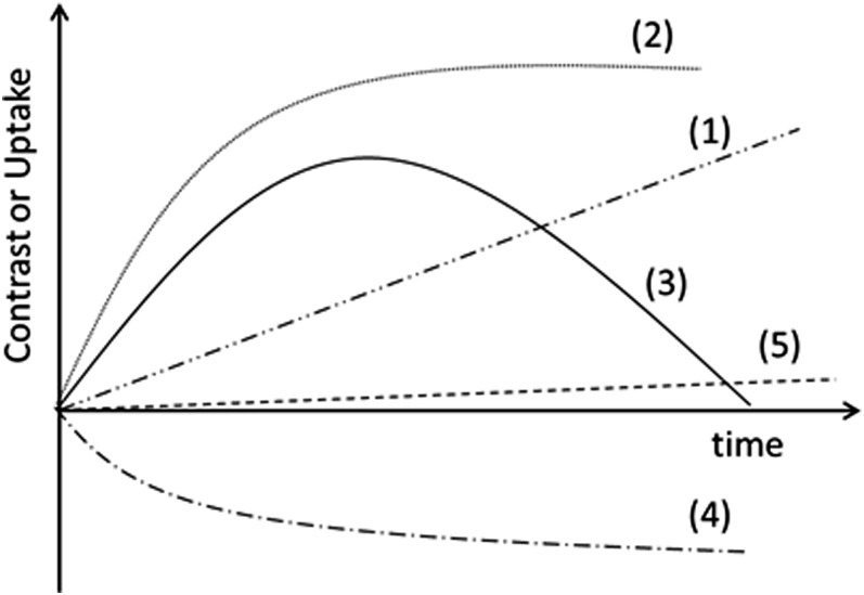
Similar to the interpretation of CM temporal patterns in MRI, changes in iodine uptake and contrast over time (referred to as time–iodine and time–contrast kinetic curves, respectively) were classified into five types depending on their patterns (Figure 1), following common use in CEDM: (1) continuous enhancement, (2) early enhancement followed by plateau, (3) washout pattern, (4) negative enhancement and (5) non-significant enhancement. The type-5 curve classification (consistent with zero) was assigned to curves that displayed values consistently smaller than, or of the order of, 0.4 mg cm−2 during the 5 min of analysis.
Figure 1.
Classification of time–iodine and time–contrast curves. (1) Continuous enhancement, (2) early enhancement followed by plateau, (3) washout pattern, (4) decreasing enhancement and (5) non-significant enhancement.
Blood and lymphatic microvessel density
Formalin-fixed, paraffin-embedded tissue blocks were sliced in 3-μm thick sections and mounted on electrostatically charged slides. Sections were deparaffinized in xylene and sequentially washed twice in 100% alcohol and in 95%, 90%, 80% and 70% alcohol for 2 min, and then washed twice with phosphate-buffered saline pH 7.4. Sections were then treated with target retrieval solution, pH 9 (DAKO®; DAKO North America, Carpinteria, CA) in a pressure cooker (122–125 °C at 15–24 psi) for 20 min. Endogenous peroxidase activity was blocked by incubating the cells in 3% hydrogen peroxide. Non-specific background staining was prevented by Protein Block, Serum-Free (DAKO) for 30 min. Antibodies were incubated overnight at 4 °C. Primary antibodies were anti-CD105 rabbit polyclonal antibody (clona SN6h; DAKO) for blood vessels, and anti-podoplanin (D2-40) mouse monoclonal antibody (clone D2-40; DAKO) for normal or neoplastic lymphatic vessels, in 1/100 dilution. Visualization was carried out using a solution of 3,3ʹ-diamminobenzidine tetarahydroclorate (DAKO) counterstaining with 0.2% methylene blue. Each run included a negative control without antibody. Microscopic observations were made by two independent pathologists who counted microvessels in five 200× fields. Count estimates were the average number of vessels and their standard deviation. The investigator performing microvessel analysis was blinded to the pathology results.
Statistical analysis
Correlations between blood and lymphatic MVD, as well as between MVD and CEDM enhancement parameters (iodine uptake and MPV) were analyzed on SPSS®, v. 21 (IBM Corp., New York, NY; formerly SPSS Inc., Chicago, IL) using Spearman correlation coefficient ρ for non-parametric data. A strong correlation was assumed if ρ > 0.7 at a level of statistical significance of p < 0.05. The Kolmogorov–Smirnov test was applied to the frequency distribution of kinetic curve types to compare benign and malignant lesions.
RESULTS
Patients
Table 1 lists data corresponding to the 18 patients included in the study. Identification number corresponds to their enrolment sequence. Among the 11 patients with cancer, 10 had invasive ductal carcinoma, 3 of them with necrosis, and 1 had ductal carcinoma in situ. Among the seven benign lesions, six were fibroadenomas (one cellular fibroadenoma) and one microglandular adenosis. The age distribution for benign cases was 36–50 years (mean = 42.6 years, median= 42.0 years) and for cancer patients was 38–68 years (mean = 57.1 years, median = 60.0 years).
Table 1.
Patient data and measured microvessel density (MVD) and image parameters (uptake, contrast and type of time curves)
| Patient data |
Pathology |
MVD (vessels per field) |
Contrast-enhanced digital mammography results |
||||||
|---|---|---|---|---|---|---|---|---|---|
| ID | Age (years) | Malignant/benign | Lesion type | BMVD | LMVD | Iodine uptake at t = 3 min (mg iodine/cm2) | Time–iodine curve | Contrast at t = 3 min (mg iodine/cm2) | Time–contrast curve |
| 1 | 68 | M | IDCn | 48.8 | 23.6 | 2.62 | 2 | 1.89 | 2 |
| 3 | 44 | B | BF | 17.8 | 7.6 | 0.55 | 5 | −0.85 | 4 |
| 4 | 62 | M | IDC | 49.8 | 28.4 | 1.06 | 2 | 1.25 | 2 |
| 5 | 40 | B | BF | 23.8 | 6.6 | 1.78 | 1 | 1.18 | 1 |
| 6 | 54 | M | IDC | 67.4 | 41.2 | 1.75 | 3 | 2.17 | 3 |
| 7 | 50 | B | BF | 21.2 | 11.0 | 5.68 | 2 | 3.65 | 2 |
| 8 | 47 | B | BA | 27.2 | 14.6 | 1.54 | 2 | 0.77 | 2 |
| 9 | 60 | M | IDC | 60.6 | 46.6 | −0.98 | 4 | −0.64 | 4 |
| 11 | 56 | M | IDC | 45.2 | 17.0 | 1.83 | 1 | 1.05 | 1 |
| 12 | 61 | M | DCIS | 46.0 | 26.2 | −0.84 | 4 | −0.44 | 5 |
| 14 | 62 | M | IDC | 55.6 | 34.6 | 0.95 | 3 | −0.40 | 5 |
| 15 | 45 | M | IDC | 43.6 | 33.8 | 0.44 | 5 | −0.44 | 5 |
| 18 | 39 | B | BF | 20.2 | 8.0 | 1.51 | 2 | 1.68 | 2 |
| 21 | 42 | B | BF | 22.6 | 9.8 | 0.30 | 5 | 0.54 | 5 |
| 23 | 36 | B | BF | 20.0 | 5.6 | 4.95 | 2 | 3.77 | 2 |
| 24 | 38 | M | IDCn | 63.2 | 40.4 | 3.51 | 2 | 1.98 | 3 |
| 25 | 63 | M | IDCn | 59.0 | 43.4 | 4.69 | 2 | 4.22 | 2 |
| 26 | 59 | M | IDC | 60.6 | 33.6 | 1.38 | 2 | 1.48 | 2 |
B, benign; BA, microglandular adenosis; BF, fibroadenoma; BMVD, blood MVD; DCIS, ductal carcinoma in situ; ID, identification; IDC, invasive ductal carcinoma; IDCn, IDC with necrosis; LMVD, lymph MVD; M, malignant.
Only information related to the 18 patients included in the study is shown; the listed patient identification corresponds to the enrolment sequence.
Image acquisition
All patients had a set of six images, as described above. The real acquisition time of the CM images was, typically, equal (within 6–10 s) to the nominal t = 1, 2, 3 and 5 min. For two patients in the analysis, the sequence got slightly delayed after the first CM image, and the real times were from 0.5 to 1 min later than the nominal. However, all registered a temporal sequence of four CM images, and the time evolution of the uptake did not indicate any effect related to the delayed acquisition.
Contrast-enhanced digital mammography image analysis
Image analysis was based on a custom-made MatLab (The MathWorks Inc., Natick, MA) code. Before subtraction, registration was performed to correct for possible patient motion during the procedure. Average corrections to align pairs of fiducial markers were about 15 pixels (i.e. 1.5 mm). Two patients required corrections twice these values, and one patient required corrections three times larger than these values. The correction required to register the images for SET, involving a series of five images, was not significantly smaller than DETm (six images) probably due to the fact that the additional image in DETm was a mask taken at the beginning of the procedure, and patient motion tended to show at times after the CM had been injected.
Both modalities, SET and DETm [Equations (1) and (2), respectively] resulted in similar PVs in the subtracted images; differences were, on average, <3% of the MPV in the lesion ROI and in the contrast. This served as a verification of the quantitative nature of the “correctness” of energy compensation and supports the quantitative nature of the measurements. Differences between SET and DETm were considered not statistically significant, and in what follows, the analysis refers to the DETm values.
CEDM results reported in Table 1 show the iodine mass thickness at 3 min, as representation of the uptake by each patient. Also shown are the type of time–iodine curve (Figure 1), the contrast at 3 min and the type of time–contrast curve. Iodine uptake in terms of iodine mass thickness in Table 1 represents values in the lesion ROI; values ranged between 5.7 mg iodine cm−2 (maximum) and about −1 mg iodine cm−2 (minimum). Among the five highest iodine uptake values (>2 mg iodine cm−2), two were benign cases. Negative values of iodine uptake have been previously observed, and those cases have been either dismissed as artefacts generated by the digital detector5 or referred to as “black carcinoma” probably caused by patient motion.12 We observed negative uptake (i.e. time–iodine curve type 4) in one patient with invasive ductal carcinoma (Patient 9) and one with ductal carcinoma in situ (Patient 12). A possible explanation for this unexpected result could be motion between acquisitions. The already mentioned realignment of the fiducial marks required a relatively low displacement for Patient 9 (1.1 mm) and a larger than average for Patient 12 (2.6 mm).
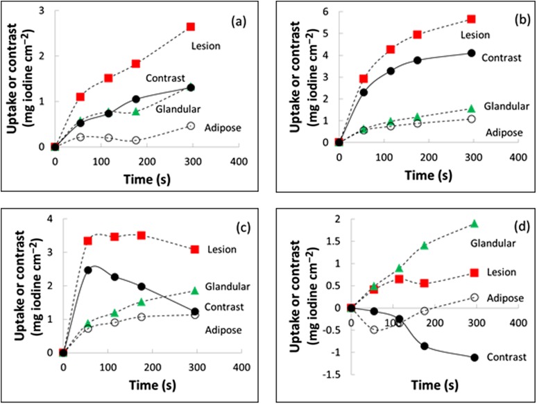
Figure 2 shows representative time–iodine and time–contrast curves. The chosen cases illustrate that uptake in the adipose tissue (open circles) was predominantly smaller than in the glandular tissue (green triangles) or lesion (red squares), as expected. Uptake in the lesion tended to be higher than in glandular tissue, but exceptions occurred as shown by Figure 2d; this situation, which led to negative contrast, was observed in one cancer and one benign lesion.
Figure 2.
Typical time–uptake and time–contrast curves (a) for Patient 11, (b) Patient 23, (c) Patient 24 and (d) Patient 3. Lines are a guide to the eye. The regions of interest for the tissue components were drawn by an experienced radiologist.
Cancer lesions displayed all types of time–iodine curves. The most frequent observation was Type-2 (plateau) curves (5 out of 11, 45%), 2 lesions displayed Type-3 curve (washout) and 2 cases displayed Type-4 curve (negative). Among the seven benign lesions, one patient showed Type-1, four (57%) showed Type-2 and two Type-5 (zero) iodine uptake curves. If Curves 1, 2 and 3 (continuous increase, plateau and washout) were considered indicators of iodine enhancement, the technique would show 62% sensitivity, 40% specificity, 73% positive-predictive value and 29% negative-predictive value.
Contrast, the difference between iodine thickness at the lesion and the normal glandular tissue, generally followed the lesion uptake values and trends. In Table 1, contrast at 3 min reached maximum values of 4.2 mg iodine cm−2 (Patient 25, cancer lesion) and 3.8 mg iodine cm−2 (Patient 23, benign lesion). These patients also showed high values of iodine uptake. In the two cases of negative uptake, contrast was negative or non-significant. Type-2 was the most frequent type of curve for malignant (36%) and benign lesions (57%). Two Type-3 contrast curves were observed among the cancer lesions (18%). If time–contrast curves Type 1, 2 and 3 were considered indicators of contrast enhancement, CEDM shows 58% sensitivity, 33% specificity, 64% positive-predictive value and 29% negative-predictive value.
For the comparison between the frequency distribution of time–iodine and time–contrast type of curves for benign and malignant lesions (values can be easily obtained from Table 1), the Kolmogorov–Smirnov test gave p = 0.99 and 0.89 for uptake and contrast, respectively. Similar (negative) results were obtained when comparing the distributions with respect to microvessel densities (using 30 vessels/field as threshold for malignancy). Thus, no significant difference was observed between the distributions of iodine uptake or contrast kinetic curve types for benign and cancer lesions.
Contrast-enhanced digital mammography radiological images
Figures 3–8 show representative images for selected patients. It can be observed that the breast anatomical structure has been strongly removed by subtraction.
Figure 3.
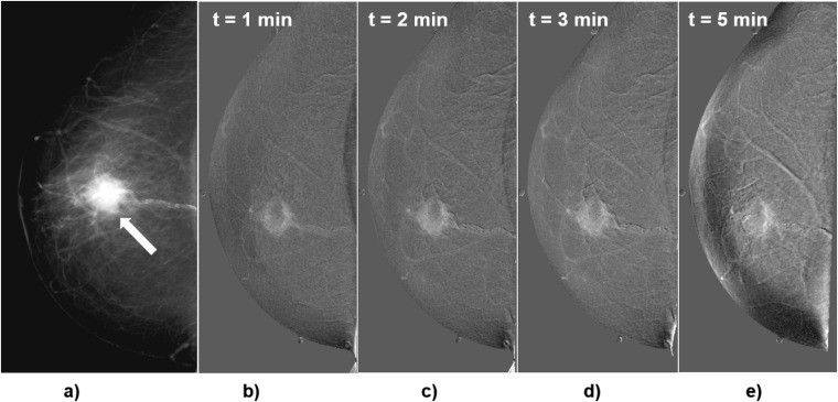
Craniocaudal images of Patient 1, invasive ductal carcinoma with necrosis. (a) Conventional diagnostic mammogram previous to the contrast medium injection (arrow indicates the lesion); (b–e) subtracted images obtained 1, 2, 3 and 5 min after the start of contrast medium injection. Subtracted images show rim enhancement of the lesion.
Figure 8.
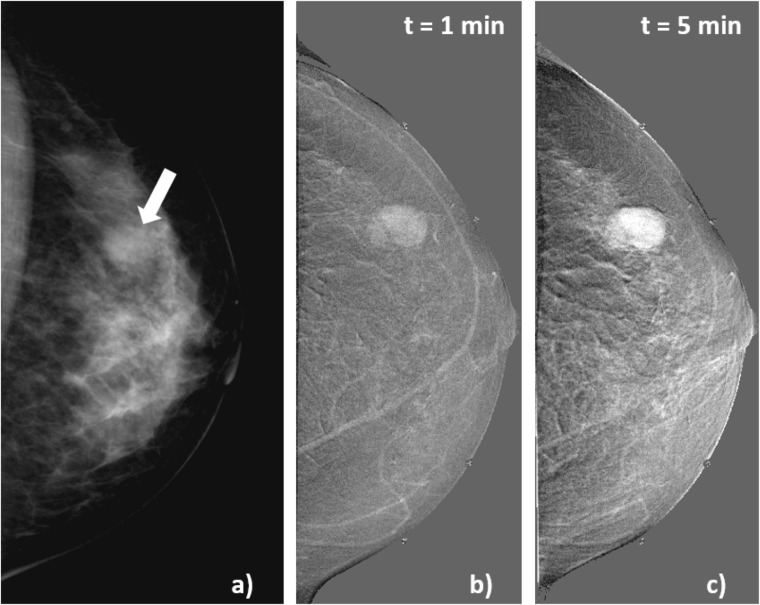
Craniocaudal images obtained in Patient 7, with cellular fibroadenoma. (a) Conventional diagnostic mammogram; the arrow indicates the lesion. Subtracted images (b) acquired 1 min and (c) 5 min after the start of contrast medium injection.
Figure 3 shows a right breast mammogram and the temporal series of subtracted images for Patient 1, 68 years old, with invasive ductal carcinoma with necrosis. The mammogram (Figure 3a) indicated a dense mass with speculated margins, 2-cm diameter, BI-RADS-5 lesion. After CM injection, CEDM images (Figure 3b–e) showed rim enhancement that increased with time, leaving a central area without CM uptake. Uptake and contrast values were relatively large, and both curves were Type 2. This case corresponds to a malignant lesion with strong iodine uptake and contrast.
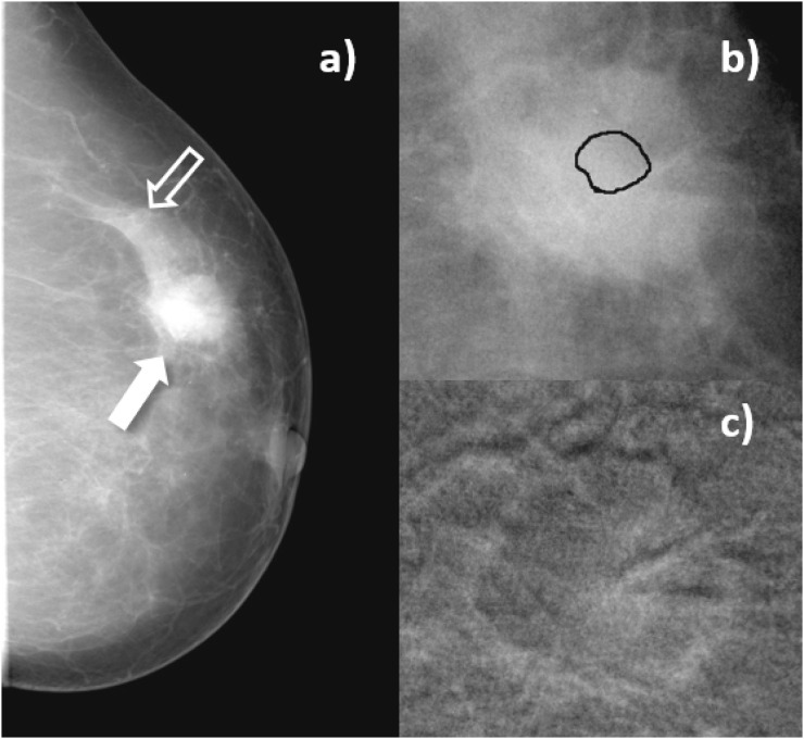
Figure 4 corresponds to Patient 4, 62 years old, invasive ductal carcinoma with an associated low-grade in situ ductal carcinoma in her left breast, detected by self-examination. The conventional mammogram (Figure 4a) showed an irregular, ill-defined 2.3-cm diameter medium-density mass, spiculated margins and lower-density central area, without calcifications (Figure 4b). This corresponded to a BI-RADS-5 lesion. After CM and subtraction, peripheral enhancement with fuzzy margins was observed (Figure 4c).
Figure 4.
Craniocaudal images of Patient 4, invasive ductal carcinoma. (a) Mammogram acquired before contrast-enhanced digital mammography procedure. Solid arrow indicates the lesion, open arrow signals a region of normal breast parenchyma; (b) enlarged view of the lesion before contrast medium (CM) injection, with the lesion region of interest drawn by the radiologist; (c) subtracted image of the same region as in (b), 3 min after start of CM injection.
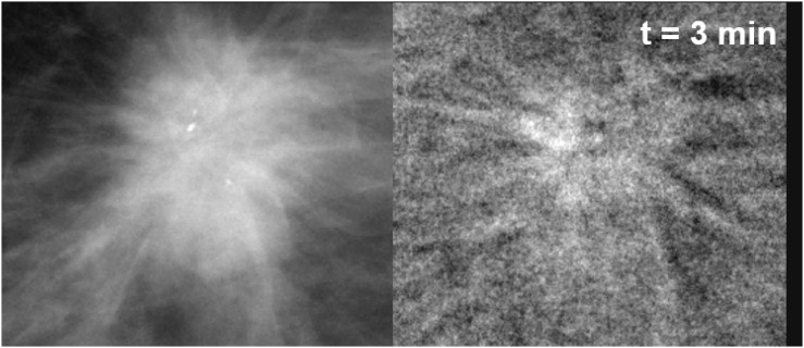
Figure 5 corresponds to Patient 6, 54 years old, 1.5-cm diameter lesion, an invasive ductal carcinoma in her right breast. The lesion appeared in the LE mask image (Figure 5a) with irregular and spiculated margins, ill-defined isodense mass, associated with calcifications. Classification was BI-RADS 5. After CM injection, in the CEDM, one observes a spiculated enhancement region (Figure 5b).
Figure 5.
Enlarged view of Patient 6 lesion region (invasive ductal carcinoma with associated low-grade in situ ductal carcinoma). (a) Mask image (for presentation) acquired at low energy before contrast medium (CM) injection; (b) subtracted image of the same region, 3 min after CM injection.
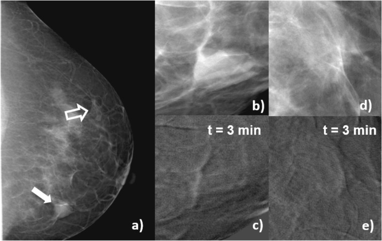
Figure 6 corresponds to Patient 3, 44 years old, with a fibroadenoma with rounded borders in her left breast (Figure 6a). Figure 6b,d are enlarged views of the lesion and a region of normal glandular tissue in the conventional mammogram. Figure 6c,e are enlarged views of the same regions in the subtracted image after 3 min of CM injection. After CM administration, there is no visible uptake in the lesion and weak uptake in the glandular tissue, and the numerical values for lesion iodine uptake and contrast were very small (consistent with zero) and negative, respectively.
Figure 6.
Craniocaudal images of Patient 3, fibroadenoma. (a) Mammogram acquired before contrast-enhanced digital mammography procedure, the solid arrow indicates the lesion, and open arrow signals a region of normal glandular tissue; (b) enlarged view of a processed (for presentation) image of the lesion before contrast medium (CM) injection; (c) subtracted image of the same region as (b) 3 min after the start of CM injection; (d) enlarged view of a processed (for presentation) image of the glandular tissue before CM injection; (e) subtracted image of the same region as (d) 3 min after the start of CM injection. In the subtracted images, uptake at the lesion region (c) is lower than at the glandular tissue (e), and the contrast is numerically negative. This patient was candidate to a biopsy due to risks factors.
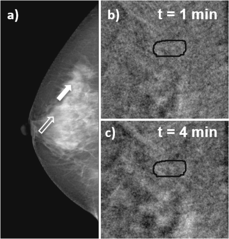
Figure 7 shows images for Patient 21, 42 years old, with focal asymmetry in right breast associated with architectural distortion observed in her screening mammogram (Figure 7a). Classification is BI-RADS 4, and biopsy indicates hyalinized fibroadenoma. After CM administration, no enhancement is observed in the lesion, as shown in Figure 7c,d, which depicts enlarged views of the lesion in the subtracted image at 1 and 4 min after CM injection.
Figure 7.
Craniocaudal images of Patient 21, hyalinized fibroadenoma. (a) Mammogram acquired before contrast-enhanced digital mammography procedure, the solid arrow indicates the lesion, and open arrow signals a region of normal glandular tissue; (b, c) subtracted images at 1 and 4 min after the start of contrast medium (CM) injection. The subtracted images show no uptake of CM at the lesion region.
Figure 8 shows images for Patient 7, 50 years old, with a cellular fibroadenoma. In the screening mammogram, the left breast displayed a 1.3-cm diameter, BI-RADS-4 lesion with hyperplasia (Figure 8a). The subtracted images shown in Figure 8b,c after 1 and 5 min of CM injection, respectively, showed that iodine uptake initiated at the centre and later became stronger at the periphery. This case is an example of a false-positive CEDM.
No additional cancers to those originally detected in mammography were discovered in the CEDM images.
Blood and lymphatic microvessel density
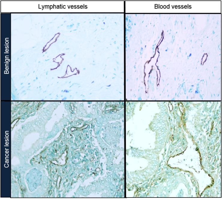
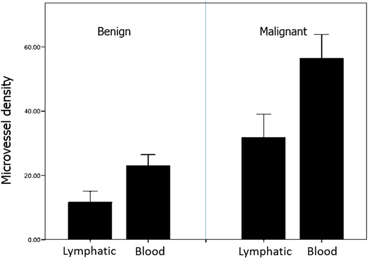
Figure 9 shows representative microscope images of lymphatic and blood microvessels for benign and cancer lesions. Figure 10 displays mean values and standard deviation of MVD measured in benign and malignant lesions. Lymphatic vessel density was, on the average, 0.6 and 0.4 times the blood vessel density for benign and cancer lesions, respectively.
Figure 9.
Microscope images of lymphatic and blood microvessels for benign and cancer lesions.
Figure 10.
Microvessel density histograms for benign and malignant lesions.
Strong correlation, according to Spearman's criteria, was found between lymphatic and blood vessels' microdensity (ρ = 0.90, p < 0.01). Given this and the linear correlation between blood and lymphatic densities, in what follows, we only analyze the blood MVD. The Spearman analysis between blood MVD and pathology (benign or cancer) also showed strong correlation (for benign cases, ρ = 0.85, p < 0.01; for cancer, ρ = 0.93, p < 0.01). Blood MVD showed no correlation (ρ = 0.58, p = 0.82) with iodine uptake, nor with contrast (ρ = 0.14, p = 0.58).
DISCUSSION
Even if the application of CEDM requires relatively simple image processing, previous reports have not always presented a detailed description of the image subtraction and evaluation of the resulting image, making quantitative comparisons difficult. Some published results were based on the subjective visualization of iodine uptake in the lesion, and in cases such as Diekmann's evaluation,13 a large variability was observed among individual radiologists. In cases where numerical values have been presented and time–intensity curves evaluated, there is no uniformity in the chosen parameter to quantify CM uptake. This encouraged the definition and investigation of quantitative descriptors that might reduce interobserver variability and facilitate the intersubject and multi-institutional comparisons of the results.
Our working protocol for image processing resulted in quantitative evaluation of iodine thickness at the lesion and contrast in ROIs defined in the subtracted images. Once the subtraction protocol had been defined, these values depended only on the ROIs chosen by the radiologist. This study showed that the ROI-drawing procedure can be uncertain, mostly due to the lack of training of (otherwise, experienced) radiologists with the specific interpretation of CEDM-subtracted images. Particularly complex was the task of defining precise boundaries of a suspected lesion ROI and a region of normal glandular tissue. Furthermore, due to the projection character of the mammogram, the ROI probably included iodine that circulated above and below the tissue of interest at the acquisition time. A rough mean estimate of the amount of iodine that could be circulating in normal glandular tissue, in columns of about the same thickness, was given by the glandular tissue intensity. Our second parameter, contrast, subtracted the glandular intensity from the lesion projection and attempted to eliminate, in a rather crude fashion, the possible iodine circulation in normal glandular tissue surrounding the lesion. However, results from contrast, being numerically different from uptake, were not qualitatively different. Slightly different ROIs (drawn by the participating radiologist to assess the robustness of the method) resulted into different numerical values for the uptake, but the pattern of time–uptake and time–contrast curves was mostly unchanged. Thus, we consider that the classification of the different time curves is one of the most solid results of this study due to its relative independence from subjective factors.
We could not identify a statistical difference between iodine uptake or time–intensity uptake curves between the 11 cancer and 7 benign cases: 73% of cancer and 71% of benign lesions showed enhancement due to CM uptake (adding up Curve-types 1, 2 and 3). Meaningful comparison with results from independent studies is difficult due to low statistics and to large variations between the previously reported results. Jong et al5 studied iodine uptake in lesions and normal tissue ROIs finding CM enhancement in 8/10 (80%) malignant lesions and no enhancement in 7/12 (58%) benign lesions. Diekmann et al14 studied in 2005, 26 lesions, and 10/16 (62.5%) of the cancers and 5/10 (50%) of the benign lesions showed uptake. In 2011, Diekmann et al13 reported results for 70 patients for 80 total lesions, and 42% of the cancer cases and 65% of the benign showed no uptake.
There are general similarities between these results and those by Diekmann,13,14 namely the failure to detect iodine enhancement in almost one third of the malignant cases, and the observation of uptake in a large fraction of benign cases (71% in this work, 35–50% in that by Diekmann et al14). Part of our efforts, as well as those by Diekmann et al,14 was to search for quantitative parameters of enhancement, attempting to test absolute as well as relative indicators. Diekmann et al14 chose iodine uptake at the lesion (absolute) and its ratio with neighbouring tissue (relative). We attempted two subtraction modalities, finding no difference between them. In the subtracted images, lesion uptake (absolute) and the difference between lesion and normal glandular tissue (relative) were quantified. The search for a relative metric was driven in both cases by the need to evaluate the effect of the under- and overlying tissue in the projection image. Both studies have concluded that no major difference could be observed between the absolute and the relative evaluations of enhancement (uptake and contrast in our terminology). Maybe, these apparently negative results should be interpreted as indication of the robustness of the evidence presented by the images themselves.
The temporal follow-up of the uptake during 5 min after the CM injection, and the classification of the uptake or contrast into time–intensity (or time–contrast) curves, has been strongly motivated by its usefulness as a diagnostic indicator in MRI.20 An early CEDM report by Diekmann et al14 discussed advantages and differences between both contrast techniques, and later Diekmann et al13 reported the apparent difficulties of visually identifying Type-3 curves by readers. Our quantitative protocol has not solved the issue, and we do not find an association between types of curves and pathology. Possibly, the arrival of iodine to most of the breast after 3 min of the beginning of injection, as shown by the adipose tissue uptakes in Figure 2, makes evaluation of the iodine in projected images at this observation time or later even more uncertain. Curves of uptake in the adipose tissue in Figure 2 indicate a tendency to show iodine as time passes.
Previous studies12 have dealt with the appearance of lesions that show “negative” iodine uptake or contrast. Figure 6 showed a case of non-significant lesion uptake, positive iodine uptake at the glandular tissue and a negative contrast. This is one of the two Type-4 curves found in the analysis, one benign and one cancer lesion. This evidence might be reflecting physiopathological changes in the mammary gland that increase uptake in fibroglandular tissue more than in the lesion, resulting in a negative contrast.
In regard to the vascular network, our results confirm previous studies in that malignant tumours show a higher number of blood and lymphatic vessels than benign lesions.21 The antibodies used to mark the vascular network of both malignant and benign lesions cannot distinguish between newly formed vessels and those already existing in the tissues.
The estimation of vessel density is an average of capillaries per area and does not provide indications as to the structure and complexity of the vascular network. It should be remembered that the vascular network of tumours is quite irregular and chaotic. Blood and lymphatic vessels are immature, and their physiology is abnormal. Fluid is irregularly retained and/or drained in different parts of the tumour. The vascular network of each tumour seems to be unique, and its structure and functionality depend of many factors. Breast cancers are a heterogeneous group of malignancies, and histological types vary substantially. Our cases included only the most frequent of breast cancer, ductal carcinoma. But, even within this restricted group, there are wide variations in structure. Tumours with abundant stroma and collagen, so called desmoplastic, tend to collapse the capillaries and have shown a lower perfusion than tumours with a lax stroma.22–25 The microenvironment is a complex histopathological structure composed mainly by a number of extracellular matrix molecules, macrophages, myoepithelial and endothelial cells and is increasingly recognized as a major regulator of carcinogenesis. Presently, there is no way to quantify the abnormality of the capillary network in a tumour and its microenvironment; thus, estimating the number of vessels is a rough estimation of the proliferation of blood and lymph capillaries that indicates the malignant nature of the tumour mass. It should be expected that the blood flow within the internal vessels' network structure of tumours will vary significantly in each case, and the kinetic curves of the radio-opaque material simply indicate the flow and the type and functionality of the vascular network in each tumour.
All these factors considered, it might seem naive to reduce to simple metrics, such as the one used here and in previous analyses, the analysis of contrast-enhanced images that show unique and different blood flow in the vascular network. More refined statistical tools, such as feature selection via texture analyses26 proposed for MRI, might add information to this complex task.
Concerning a comparison between techniques based on subtraction of breast images after the injection of CM, we recall that contrast-enhanced MRI (CEMRI) has been proposed as an adjunct to screening mammography in patients with family history or genetic predisposition to breast cancer. In these cases, the combination of CEMRI and mammography provided higher sensitivity (80–100%) and specificity (73–93%) than either imaging modality alone.20 Also, CEMRI has been found to improve the detection of multifocal and multicentric lesions27 and to be more accurate to determine pre-operative lesion extent.28 In particular, dynamic CEMRI, where the dynamics of a CM uptake are analyzed,29 has been used to infer properties of the newly formed vasculature around tumours and their spatial heterogeneity.30 Hence, the success of the dynamic contrast-uptake information provided by CEMRI has motivated this investigation with temporal CEDM. CEMRI provides advantages such as the cross-sectional (i.e., non-projective) nature of the images, the use of non-ionizing radiation and the opportunity to perform bilateral breast studies simultaneously. However, CEDM could be a potential alternative to CEMRI in cases where the high cost and limited scanner availability might limit access to MRI. This could only be achieved if CEDM is proven to perform as well as or better than CEMRI in a particular task. Recently, similar accuracy of CEDM (DE, non-temporal) and CEMRI to determine the extent of a lesion pre-operatively has been reported.31 More extensive comparisons between CEMRI and CEDM techniques are needed to identify situations in which one technique could be of potential use when the other one has shown limitations.
For a comparison of CEDM with other radiographic techniques, the main limitation of mammography (its projective two-dimensional character) has been overcome by breast tomography (breast CT) and tomosynthesis [digital breast tomosynthesis (DBT)]. The main advantage of these techniques, where a reconstruction algorithm generates few millimetres thick image slices, is the reduced superposition of tissues and thus the possible increase of the lesion conspicuity. Both DBT and breast CT have investigated the possibility of administering CM previous to image acquisition and thus obtaining “functional” images of blood circulation around lesions. Initial results of contrast-enhanced breast CT, still a non-commercial technique, have reported significantly higher enhancement for cancer than benign lesions.32 First results for contrast-enhanced DBT, obtained with an adapted commercial mammography unit, suggested that the techniques provided morphological and vascular characteristics of lesions that agreed, qualitatively, with digital mammography and MRI.33 Recently, a larger clinical study compared contrast-enhanced and non-contrast-enhanced mammography, breast CT and breast MRI.34 These authors34 concluded that all the contrast-enhanced modalities (CEDM, contrast-enhanced breast CT and CEMRI) had higher sensitivity than the conventional (non-contrast) corresponding techniques. For breast cancers, CEDM would be equivalent in diagnostic performance to dynamic CEMRI. Only further investigation will define the optimum conditions, both clinical and technical for each of these novel techniques.
CONCLUSION
CEDM is able to increase the visibility of iodine-irrigated lesions and show additional features, such as rim or spiculated borders, which can help diagnosis. However, simple image parameters and the type of kinetic curves evaluated from MPVs in ROIs, do not permit an identification of the pathology of the lesion. These results could be understood considering the heterogeneity of tumours, the dependence of CM irrigation on tissue composition and the projective nature of the mammographic image, all these affecting importantly the image of CM drain into the extracellular matrix. CEDM represents an interesting and viable addition to normal mammography. Probably, future investigations should restrict the study groups to better defined tumour characteristics, and thus identify those patients most probably benefitted by the technique and/or explore the use of more refined image process tools.
Acknowledgments
ACKNOWLEDGMENTS
The authors thank LA Medina and H Larreguy for assistance in the statistical analysis; JE Bargalló for contributions during the patient selection; ML Hill for providing iodine phantoms; and MJ Mateos for assistance in the analysis and manuscript preparation.
Contributor Information
María-Ester Brandan, Email: brandan@fisica.unam.mx.
Juan P Cruz-Bastida, Email: chdward@hotmail.com.
Iván M Rosado-Méndez, Email: rosadomendez@wisc.edu.
Yolanda Villaseñor-Navarro, Email: yolavillana@hotmail.com.
Héctor Pérez-Ponce, Email: hpponce@gmail.com.
Héctor A Galván, Email: hgalvane@gmail.com.
Flavio E Trujillo-Zamudio, Email: flaviotrujillo@gmail.com.
Patricia Sánchez-Suárez, Email: patotota80@hotmail.com.
Luis Benítez-Bribiesca, Email: benitezbribiesca@gmail.com.
FUNDING
This study was partially funded by DGAPA-UNAM grants PAPIIT IN10513 and IN107916, and Conacyt SALUD-2009-01-112374. JPC-B received support from Conacyt, Mexico, during MSc studies.
REFERENCES
- 1.International Agency for Research on Cancer. GLOBOCAN 2012. Updated 29 July 2015. Available from: http://globocan.iarc.fr [Google Scholar]
- 2.Dromain C, Balleyguier C, Adler G, Garbay JR, Delaloge S. Contrast-enhanced digital mammography. Eur J Radiol 2009; 69: 34–42. doi: 10.1016/j.ejrad.2008.07.035 [DOI] [PubMed] [Google Scholar]
- 3.Skarpathiotakis M, Yaffe MJ, Bloomquist AK, Rico D, Muller S, Rick A, et al. Development of contrast digital mammography. Med Phys 2002; 29: 2419–26. doi: 10.1118/1.1510128 [DOI] [PubMed] [Google Scholar]
- 4.Lewin JM, Isaacs PK, Vance V, Larke FJ. Dual-energy contrast-enhanced digital subtraction mammography: feasibility. Radiology 2003; 229: 261–8. [DOI] [PubMed] [Google Scholar]
- 5.Jong RA, Yaffe MJ, Skarpathiotakis M, Shumak RS, Danjoux NM, Gunesekara A, et al. Contrast-enhanced digital mammography: initial clinical experience. Radiology 2003; 228: 842–50. doi: 10.1148/radiol.2283020961 [DOI] [PubMed] [Google Scholar]
- 6.Rosado-Méndez I, Palma BA, Brandan ME. Analytical optimization of digital subtraction mammography with contrast medium using a commercial unit. Med Phys 2008; 35: 5544–57. [DOI] [PubMed] [Google Scholar]
- 7.Palma BA, Rosado-Méndez I, Villaseñor Y, Brandan ME. Phantom study to evaluate contrast-medium-enhanced digital subtraction mammography with a full-field indirect-detection system. Med Phys 2010; 37: 577–89. doi: 10.1118/1.3276733 [DOI] [PubMed] [Google Scholar]
- 8.Boone JM, Shaber GS, Tecotzky M. Dual-energy mammography: a detector analysis. Med Phys 1990; 17: 665–75. doi: 10.1118/1.596548 [DOI] [PubMed] [Google Scholar]
- 9.Cruz-Bastida JP, Rosado-Méndez I, Pérez-Ponce H, Villaseñor Y, Galván HA, Trujillo-Zamudio FE, et al. Contrast optimization in clinical contrast-enhanced digital mammography images. In: Maidment ADA, Bakic PR, Gavenonis S, eds. IWDM 2012, LNCS 7361. Berlin, Heidelberg: Springer-Verlag; 2012. pp. 17–23. [Google Scholar]
- 10.Ahmed Z, Bicknell R. Angiogenic signalling pathways. In: Martin S, Murray C, eds. Angiogenesis protocols. New York: Humana Press; 2009. pp. 3–24. [DOI] [PubMed] [Google Scholar]
- 11.Charnley N, Donaldson S, Price P. Imaging angiogenesis. In: Martin S, Murray C, eds. Angiogenesis protocols. New York: Humana Press; 2009. pp. 25–51. [DOI] [PubMed] [Google Scholar]
- 12.Dromain C, Balleyguier C, Muller S, Mathieu MC, Rochard F, Opolon P, et al. Evaluation of tumor angiogenesis of breast carcinoma using contrast-enhanced digital mammography. AJR Am J Roentgenol 2006; 187: W528–37. doi: 10.2214/AJR.05.1944 [DOI] [PubMed] [Google Scholar]
- 13.Diekmann F, Freyer M, Diekmann S, Fallenberg EM, Fischer T, Bick U, et al. Evaluation of contrast-enhanced digital mammography. Eur J Radiol 2011; 78: 112–21. doi: 10.1016/j.ejrad.2009.10.002 [DOI] [PubMed] [Google Scholar]
- 14.Diekmann F, Diekmann S, Jeunehomme F, Muller S, Hamm B, Bick U. Digital mammography using iodine-based contrast media: initial clinical experience with dynamic contrast medium enhancement. Invest Radiol 2005; 40: 397–404. doi: 10.1097/01.rli.0000167421.83203.4e [DOI] [PubMed] [Google Scholar]
- 15.Hasan J, Byers R, Jayson GC. Intra-tumoural microvessel density in human solid tumours. Br J Cancer 2002; 86: 1566–77. doi: 10.1038/sj.bjc.6600315 [DOI] [PMC free article] [PubMed] [Google Scholar]
- 16.American College of Radiology. Breast imaging reporting and data System® (BI-RADS®) 4. Reston, VA: American College of Radiology; 2003. [Google Scholar]
- 17.Ayala-Domínguez L, Brandan ME. On the effect of FineView, mean energy and anti-scatter grid on the DQE of a mammography system. Radiat Meas 2013; 59: 176–82. doi: 10.1016/j.radmeas.2013.06.009 [DOI] [Google Scholar]
- 18.Schaefer S, McPhail T, Warren J. Image deformation using moving least squares. ACM Trans Graph 2006; 25: 533–40. doi: 10.1145/1141911.1141920 [DOI] [Google Scholar]
- 19.Hill ML, Mainprize JG, Mawdsley GE, Yaffe MJ. A solid iodinated phantom material for use in tomographic x-ray imaging. Med Phys 2009; 36: 4409–21. doi: 10.1118/1.3213516 [DOI] [PubMed] [Google Scholar]
- 20.Warner E, Messersmith H, Causer P, Eisen A, Shumak R, Plewes D. Systematic review: using magnetic resonance imaging to screen women at high risk for breast cancer. Ann Intern Med 2008; 148: 671–9. doi: 10.7326/0003-4819-148-9-200805060-00007 [DOI] [PubMed] [Google Scholar]
- 21.Place AE, Jin Huh S, Polyak K. The microenvironment in breast cancer progression: biology and implications for treatment. Breast Cancer Res 2011; 13: 227. doi: 10.1186/bcr2912 [DOI] [PMC free article] [PubMed] [Google Scholar]
- 22.Levental KR, Yu H, Kass L, Lakins JN, Egeblad M, Erler JT, et al. Matrix crosslinking forces tumor progression by enhancing integrin signaling. Cell 2009; 139: 891–906. doi: 10.1016/j.cell.2009.10.027 [DOI] [PMC free article] [PubMed] [Google Scholar]
- 23.Barker HE, Chang J, Cox TR, Lang G, Bird D, Nicolau M, et al. LOXL2-mediated matrix remodeling in metastasis and mammary gland involution. Cancer Res 2011; 71: 1561–72. doi: 10.1158/0008-5472.CAN-10-2868 [DOI] [PMC free article] [PubMed] [Google Scholar]
- 24.Li H, Lan L, Sennett C, Giger M. SU-E-J-248: contributions of tumor and stroma phenotyping in computer-aided diagnosis. Med Phys 2015; 42: 3323. doi: 10.1118/1.4924334 [DOI] [Google Scholar]
- 25.Phamduy TB, Sweat RS, Azimi MS, Burow ME, Murfee WL, Chrisey DB. Printing cancer cells into intact microvascular networks: a model for investigating cancer cell dynamics during angiogenesis. Integr Biol (Camb) 2015; 7: 1068–78. doi: 10.1039/C5IB00151J [DOI] [PMC free article] [PubMed] [Google Scholar]
- 26.Agner SC, Soman S, Libfeld E, McDonald M, Thomas K, Englander S, et al. Textural kinetics: a novel dynamic contrast-enhanced (DCE)-MRI feature for breast lesion classification. J Digit Imaging 2011; 24: 446–63. doi: 10.1007/s10278-010-9298-1 [DOI] [PMC free article] [PubMed] [Google Scholar]
- 27.Houssami N, Ciatto S, Macaskill P, Lord SJ, Warren RM, Dixon JM, et al. Accuracy and surgical impact of magnetic resonance imaging in breast cancer staging: systematic review and meta-analysis in detection of multifocal and multicentric cancer. J Clin Oncol 2008; 26: 3248–58. doi: 10.1200/JCO.2007.15.2108 [DOI] [PubMed] [Google Scholar]
- 28.Fischer U, Kopka L, Grabbe E. Breast carcinoma: effect of preoperative contrast-enhanced MR imaging on the therapeutic approach. Radiology 1999; 213: 881–8. doi: 10.1148/radiology.213.3.r99dc01881 [DOI] [PubMed] [Google Scholar]
- 29.Taylor JS, Tofts PS, Port R, Evelhoch JL, Knopp M, Reddick WE, et al. MR imaging of tumor microcirculation: promise for the new millennium. J Magn Reson Imaging 1999; 10: 903–7. doi: [DOI] [PubMed] [Google Scholar]
- 30.Yang X, Knopp MV. Quantifying tumor vascular heterogeneity with dynamic contrast-enhanced magnetic resonance imaging: a review. J Biomed Biotechnol 2011; 2011: 732848. doi: 10.1155/2011/732848 [DOI] [PMC free article] [PubMed] [Google Scholar]
- 31.Fallenberg EM, Dromain C, Diekmann F, Engelken F, Krohn M, Singh JM, et al. Contrast-enhanced spectral mammography versus MRI: initial results in the detection of breast cancer and assessment of tumour size. Eur Radiol 2014; 24: 256–64. doi: 10.1007/s00330-013-3007-7 [DOI] [PubMed] [Google Scholar]
- 32.Prionas ND, Lindfors KK, Ray S, Huang SY, Beckett LA, Monsky WL, et al. Contrast-enhanced dedicated breast CT: initial clinical experience. Radiology 2010; 256: 714–23. doi: 10.1148/radiol.10092311 [DOI] [PMC free article] [PubMed] [Google Scholar]
- 33.Chen SC, Carton AK, Albert M, Conant EF, Schnall MD, Maidment AD. Initial clinical experience with contrast-enhanced digital breast tomosynthesis. Acad Radiol 2007; 14: 229–38. doi: 10.1016/j.acra.2006.10.022 [DOI] [PMC free article] [PubMed] [Google Scholar]
- 34.Chou CP, Lewin JM, Chiang CL, Hung BH, Yang TL, Huang JS, et al. Clinical evaluation of contrast-enhanced digital mammography and contrast enhanced tomosynthesis—comparison to contrast-enhanced breast MRI. Eur J Radiol 2015; 84: 2501–8. doi: 10.1016/j.ejrad.2015.09.019 [DOI] [PubMed] [Google Scholar]


