Abstract
Functional Electrical Stimulation is a commonly used method in clinical rehabilitation and research to trigger useful muscle contractions by electrical stimuli. In this work, we present a stimulation system for transcutaneous electrical stimulation that gives extensive control over the stimulation waveform and the stimulation timing. The system supports electrode arrays, which have been suggested to achieve better selectivity and to simplify electrode placement. Electromyography (EMG) measurements are obtained from the active stimulation electrodes (between the stimulation pulses) or from separate surface EMG electrodes. The modular design enables the implementation of sophisticated stimulation control systems including external triggers or wireless sensors. This is demonstrated by the standalone implementation of a feedback-controlled drop foot neuroprosthesis, which uses a wireless inertial sensor for realtime gait phase detection and foot orientation measurement.
Key Words: functional electrical stimulation, electromyography, electrode array, stimulation system
Functional Electrical Stimulation (FES) via surface electrodes is a well-known technique for the rehabilitation of stroke survivors or individuals with spinal cord injuries1. Usually a small electrical pulse, typically current-controlled with amplitudes between 1 and 150mA and pulse widths up to 500µs, is applied via self-adhesive surface electrodes of different sizes. The repeated application of such an electrical stimulus, typically with stimulation frequencies between 20 and 100Hz, results in the contraction of the muscle tissue underneath the surface electrodes. In most cases, the electrical pulse consists of at least a positive and a negative part with equal amplitude and pulse width. A 100µs long interval with no stimulation between the two parts is provided by some systems to increase the stimulation effect of the second pulse part. Recent studies suggest that further optimization of the waveform can increase the muscle response to the stimulus.2
The identification of suitable elements within electrode arrays or multi-pad electrodes is another area where more control over the stimulation waveform is desirable.3 Electrode arrays are used in an increasing number of research contributions, since they can help to increase the selectivity of muscle activation and to delay muscle fatigue. Electrode arrays consist of multiple small elements, which can be combined to form virtual electrodes of various sizes and shapes. The virtual electrode can even be moved in real-time within the electrode array until the best position is found.4 Likewise, one can use different regions of the same electrode array to control different muscle groups simultaneously, see e.g. Salchow at al.4 Muscle fatigue can be reduced by some kind of alternating stimulation if multiple virtual electrodes that yield a similar motor response are used, see e.g. Downey et al.5 These techniques can also result in a more comfortable stimulation, requiring lower stimulation intensities, while at the same time, a more natural functional movement can be achieved. This is important for a good patient compliance and an active involvement of the patient during the therapy. Taking the patient’s intention into account can result in an higher therapy success rate6 and can be accomplished with surface electromyography (sEMG) measurements. sEMG uses two surface electrodes to record the very small electric activity produced by skeletal muscles during contraction. The almost stochastic voluntary parts (vEMG) of the sEMG signal can be used to assess the patient’s intention and to modify the FES therapy accordingly, see e.g.6 Electrical stimulation induces an EMG signal as well, the so-called M-wave. An M-wave occurs directly after an electrical stimulus and is about 1000 times larger than the vEMG, since the electric stimulus activates a large number of motor units synchronously. Control strategies based on M-waves are currently being developed and can be used to linearize the nonlinear system dynamics by adding an underlying EMG-based control loop.7 Until now, sEMG based strategies cannot be used in combination with electrode arrays, because their larger size prevents the placement of additional sEMG electrodes.
The RehaMovePro Device
Overview
The compact RehaMovePro system, depicted in Fig.1, addresses the need to alter the predefined waveform beyond amplitude, pulse width and frequency. Electrode arrays are directly supported through a demultiplexer extension, and sEMG can be recorded from the stimulation electrodes even during active stimulation. Fig. 2 depicts an overview of the device and of its components. One stimulation module features four current-controlled stimulation channels. The stimulation module is controlled by MCU1, an ARM Cortex© M4 microcontroller (STM32F407; STMicroelectronics).
Fig 1.
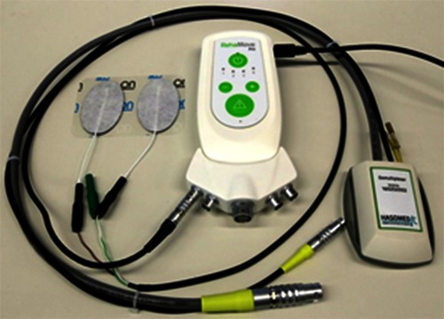
RehaMovePro stimulator with the optional science adapter, stimulation electrodes (left) and the demultiplexer extension (right).
Fig 2.
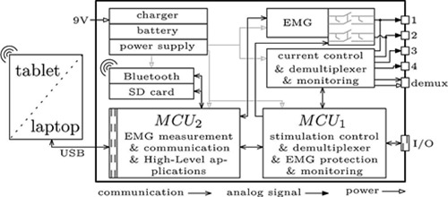
Overview of the RehaMovePro stimulator with the main components.
The task of MCU1 is to generate and monitor the stimulation waveform, as well as to control the EMG protection and the demultiplexer. The second microcontroller, MCU2 (STM32F407; STMicroelectronics), is responsible for less safety-critical tasks, like receiving data from the EMG front-end, communication with external devices, and the implementation of the software abstraction layers. This separation ensures a reliable and safe pulse generation, regardless of any additional task that might be executed in parallel.
The device is battery-powered and can be operated at least 6h with a constant 50Hz single-channel stimulation with 300µs pulse width, 20mA stimulation current and 150V supply voltage of the current controller. A secure memory (SD) card is available for advanced FES applications which require data logs to be stored. The RehaMovePro is capable to connect to Bluetooth® 2.1 devices and can receive sensor data or control commands from these devices. The optional science adapter, depicted in Fig. 1, makes various digital input and output signals, like SPI, UART and GPIOs, available through the I/O connector and provides the power supply for a demultiplexer. Among the digital output signals is the low active mute signal, which can be used to synchronize other devices with the electrical stimulation. The USB connection as well as the I/O connection of the science adapter is galvanically isolated to prevent ground loops and to ensure patient safety.
Device
The device features three abstraction layers: low-level, mid-level and high-level. The low-level layer allows explicit manipulation of every aspect of the stimulation waveform and the stimulation timing but demands higher performance from the communication link and from the PC / tablet computer running the control program. Each stimulation pulse must be initiated by the control program, which enables individual, non-periodic stimulation patterns. The mid-level layer implements a minimalistic command set with only the most common stimulation parameters. The corresponding stimulation commands are generated directly by the MCU1 with the requested stimulation frequency. The fact that the timing-sensitive generation of stimulation commands is done by the MCU1 reduces the performance requirements of the control program and the communication link. The high-level layer is less precisely defined, since it is very application-specific. Common to all high-level applications is the fact that the FES control program runs on MCU2, which facilitates mobile standalone FES applications. An example will be given in Section III. For the low-level layer, a connection via USB is necessary to guaranty the desired performance, whereas for the mid-level and the high-level layer Bluetooth® wireless connections are feasible without loss of performance.
Adjustable Stimulation Waveform
An important feature of the introduced stimulation system is the extensive level of control over the waveform used for electrical stimulation. The desired waveform can be described by up to 16 characteristic points, which are connected by piecewise constant interpolation. Each point is described by a duration tdi and a current ii. Future development will also allow other interpolation forms besides the currently used piecewise constant interpolation. In Fig. 3 a) the configuration for a biphasic pulse is shown. Any number of waveforms can be created this way, as exemplarily shown in Fig. 3 b), c) and d). The duration tdi of each point can be chosen in 1µs steps between 10µs and 4095µs. The current ii has a resolution of 0.5mA and is limited to ±150mA at the highest. However, the maximum current also depends on the resistance of the skin-electrode interface and the selected maximum supply voltage of the current control, which can be chosen from 30V to 150V in 30V steps. Having a current resolution of 0.5mA allows a more precise functional control and facilitates control strategies where a continuous control signal like the charge q = td × i is assumed.
Fig 3.
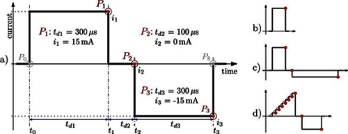
Pulse configuration for a) a standard biphasic pulse, b) a monophasic pulse, c) an unsymmetrical biphasic pulse and d) a custom waveform.
The stimulation frequency is limited by the internal data processing duration and the duration of the stimulation pulse. For single channel stimulation with the 300µs biphasic waveform depicted in Fig. 3 a), the maximum stimulation frequency is as high as 770Hz. Using four channels, the maximum stimulation frequency is as high as ~190Hz, due to the single current source.
EMG Measurement
Surface electromyography (sEMG) measurements are supported by two of the four stimulation channels through a protected 24bit EMG front-end (ADS1294, Texas Instruments), which supports sampling frequencies of 1kHz, 2kHz or 4kHz. The protection circuit enables sEMG recordings even during active stimulation. The remaining voltage transients from the stimulation pulse can be removed with a non-causal high-pass filter. The protection circuit can also be used to reduce the remaining voltage by shorting the pathways coming from the two electrodes, just after the stimulation pulse has finished. The start time and the duration of these shorting’s can be adapted in realtime.
The voluntary part of the EMG signal can be extracted from the filtered EMG signal and used afterwards to trigger the electrical stimulation or even to control the stimulation intensity. EMG can also be measured from the last connected elements within an electrode array. If the virtual EMG electrodes within the electrode array differ from the last virtual stimulation electrode, an empty stimulation pulse command can be used to set the correct demultiplexer configuration.
Electrode Array Support
The RehaMovePro supports electrode arrays through an optional demultiplexer extension. All necessary support systems, like the power supply or the control system, are integrated into the stimulator. The demultiplexer configuration is applied once for every stimulation waveform. The maximum stimulation frequency for the single channel stimulation with the 300µs biphasic waveform over an electrode array is as high as 500Hz, because of the additional set-up time of the demultiplexer. The maximum number of directly connected array elements is limited by software to 512. However, the currently available demultiplexer supports electrode arrays with up to 61 elements. From these elements, 48 are active elements, 2 are counter elements and 11 can be active or counter elements. Because of the modular design, project-specific demultiplexer extensions with different element combinations can be developed with little effort.
Software Interface
The low-level and mid-level abstraction layers are directly supported by a dynamic or static linked C library, available for Windows, Linux (64bit and ARM) and OS X. This library simplifies the integration into custom applications or environments like Matlab/Simulink, Scilab/Xcos, LabVIEW or in Python. Such an integration is already available for Simulink with support for the low-level layer as well as for the mid-level layer.
Autonomous Feedback-Controlled Drop Foot Stimulator
During clinical evaluation of new FES applications or for mobile applications, an extensive set-up with a PC-based control system is not suitable and the wiring may even influence the results, especially for mobile FES applications. If the FES control system is implemented on the stimulation device, this interference is eliminated. The overall set-up resembles the established rehabilitation tools, which may help to overcome reservations from clinicians or patients towards the new therapy. The RehaMovePro device supports the implementation of such FES applications within the high-level abstraction layer.
The autonomous feedback-controlled drop foot stimulator, which has been developed during the AperoStim project,8,9 is an example for such a high-level application. Drop foot is a common condition in stroke survivors, where the individual is not able to sufficiently lift the foot during walking. The presented system, which is shown in Fig. 4, consists of a RehaMovePro device, a wireless inertial sensor (IMU) placed on the foot and a tablet computer with a graphical user interface for remote control of the device and for optional parameter adjustments. The entire FES control system is implemented on the microcontroller MCU2, which makes the application independent from any timing requirements imposed by the stimulation pulse generation, which is implemented on MCU1. The RehaMovePro connects via Bluetooth® with the foot/shoe-mounted inertial sensor and receives 3D accelerometer and gyroscope readings with an update rate of 100Hz. The inertial data is used for two purposes: to calculate the gait phase in real-time10 and to determine the foot orientation angles.11The gait phase is used to trigger the functional stimulation at the toe-off gait event, to ensure sufficient foot to ground clearance. During the subsequent step, stimulation intensity trajectories, depicted in Fig. 5 a) bottom, are applied to two stimulation channels, which influence the pitch and roll motion of the foot (corresponding to dorsiflexion and eversion, depicted in Fig. 5 a) top). These trajectories are optimized by two iterative learning control algorithms. The optimization is based on the comparison of the measured foot motion and a desired reference motion, which is automatically adjusted to the individual gait of the patient.9
Fig 4.
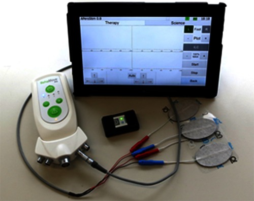
Autonomous Feedback-Controlled Drop Foot Stimulator consists of a) RehaMovePro, b) wireless inertial sensor, c) tablet computer with the graphical user interface.
Fig 5.
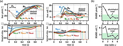
Experimental results from a trial with a chronic drop foot patient.9 (a) The stimulation intensities are adapted from stride to stride in order to generate the desired foot motion during swing phase. Dots mark heel-rise and initial contact of each stride. Starting from conventional high trapezoidal profiles (ufro,0 and ulat,0), the ILC adjusts the frontal and lateral stimulation intensity trajectories from trial to trial and thereby improves the foot pitch and roll angle trajectories (Φi and ψi ) from stride to stride. (b) Root-mean-square errors of the foot pitch and roll (data from same trial) are quickly reduced to the ranges of natural variance found in healthy subjects walking at similar velocities. Reproduced with the permission of IFAC. © IFAC 2015. The original figure was published in,9 and can be found using the Digital Object Identifier (DOI) doi:10.1016/j.ifacol.2015.10.158.
The reference trajectories, as well as a number of stimulation parameters, can be altered via the graphical user interface of the corresponding tablet computer application. The measured foot angles and the resulting stimulation intensities can be viewed in real-time on the tablet computer, which allows an objective assessment by the clinician. The foot angles as well as the stimulation trajectories are also saved to a memory card on the RehaMovePro for post-processing and analysis by the clinician. The algorithms were initially developed in C on a regular PC and then transferred to the RehaMovePro. This approach allows convenient development and testing with environments like Simulink or Xcos.
Except for the ILC update algorithm, none of the algorithms were optimized for the use on a microcontroller, since the microcontroller features a floating point unit and about 512kB of RAM.
The MCU2 program consists of the two main parts: a) IMU data acquisition and processing and b) stimulation application. Part a) is executed every 10ms and includes the reception of IMU data, as well as the calculation of the current gait phase and the current foot angles, which takes about 4ms in total. Part b) is executed every 20ms and includes the calculation of the pulse widths and currents of the next stimulation intensities q1i and q2i and sending the resulting low-level commands to MCU1, which takes less than 1ms in total. The ILC-based optimization of the stimulation parameters, which is performed after each stride of the paretic foot, takes longer than the 5ms that are available after completion of the previous calculations. Therefore, the ILC update function was split into five parts, which fit into the available time slot of subsequent processing intervals. The available memory was more than sufficient, despite the wasteful usage of debug signals. The moderate MCU workload and the available memory indicate that larger ILC-based FES application are feasible, for example simultaneous feedback-control of the foot motion and the knee motion by additional stimulation of the hamstrings or quadriceps muscles.
Fig. 5 shows the foot angles Φi and ψi for step i together with the corresponding, optimized stimulation trajectories ufro,i and ulat,i from a trial with a chronic drop foot patient.
In conclusion, we presented the stimulation system RehaMovePro, which supports user-defined stimulation waveforms, surface EMG recordings and electrode arrays for both stimulation and sEMG recordings. The rechargeable, mobile device can be used for advanced, independent FES applications, which may include external wireless sensors, sophisticated data processing, complex control algorithms and wireless connections to display or control devices. We demonstrated this with a successful implementation of a RehaMovePro high-level application: a feedback-controlled drop foot neuroprosthesis. Future work will include additional interpolation options and a universal demultiplexer extension with support for two sEMG channels. Further research will also focus on adapting the M-wave-based FES control strategy presented in Klauer et al.7 towards a high-level application that simplifies the dynamics of electrical stimulation of muscle.
Acknowledgement
This work was partially funded by the German Federal Ministry of Education and Research (BMBF) within the projects BeMobil (FKZ 16SV7069K) and APeroStim (FKZ 01EZ1204B) and by European project RETRAINER (Horizon 2020, Research and Innovation Program, grant agreement No 644721).
Contributor Information
Kristian Kociemba, Email: kristian.kociemba@hasomed.de.
Carsten Behling, Email: carsten.behling@hasomed.de.
Björn Kuberski, Email: bjoern.kuberski@hasomed.de.
Sebastian Becker, Email: sebastian.becker@hasomed.de.
Thomas Schauer, Email: schauer@control.tu-berlin.de.
References
- 1.Popovic D., Sinkjaer T. Control of Movement for the Physically Disabled: Control for Rehabilitation Technology, 2nd ed Aalborg: Springer Verlag, 2000. [Google Scholar]
- 2.Luna JV, Krenn M, Ramíez JC, Mayr W. Use of an Inter-Phase Pause to Increase the Efficiency of Biphasic Pulses on Transcutaneous Electrical Stimulation. Biomedical Engineering / Biomedizinische Technik 2014;59: 1045–148. [Google Scholar]
- 3.Valtin M, Seel T, Raisch J, Schauer T. Iterative learning control of drop foot stimulation with array electrodes for selective muscle activation, in Preprints of the 19th World Congress. The International Federation of Automatic Control, Cape Town, South Africa: 2014;6586–92. [Google Scholar]
- 4.Salchow C, Valtin M, Seel T, Schauer T. Controlled interpolation strategy for virtual electrodes in arrays, in 20th Annual International FES Society Conference, La Grande-Motte, France, 2016. [Google Scholar]
- 5.Downey RJ, Ambrosini E, Ferrante S, et al. Asynchronous Stimulation with an Electrode Array Reduces Muscle Fatigue During FES Cycling, in Proc Int Func Elect Stimul Soc, Banff, Canada, 2012; 154–7. [Google Scholar]
- 6.Ambrosini E, Ferrante S, Schauer T, et al. A myocontrolled neuroprosthesis integrated with a passive exoskeleton to support upper limb activities. J Electromyog Kinesiol 2014;24:307–7. [DOI] [PubMed] [Google Scholar]
- 7.Klauer C, Raisch J, Schauer T. Linearisation of electrically stimulated muscles by feedback control of the muscular recruitment measured by evoked EMG, in Proc. of the 17th International Conference on Methods and Models in Automation and Robotics, IEEE, Międzyzdroje, Poland, 2012;108–13. [Google Scholar]
- 8.Seel T, Werner C, Raisch J, Schauer T. Iterative Learning Control of a Drop Foot Neuroprosthesis – Generating Physiological Foot Motion in Paretic Gait by Automatic Feedback Control. Control Engineering Practice 2016:48:87–97. [Google Scholar]
- 9.Seel T, Valtin M, Werner C, Schauer T. Multivariable Control of Foot Motion During Gait by Peroneal Nerve Stimulation via two Skin Electrodes. IFAC-Papers OnLine 2015:48:315-20. [Google Scholar]
- 10.Seel T, Landgraf L, Escobar VC, Raisch J, Schauer T. Online gait phase detection with automatic adaption to gait velocity changes using accelerometers and gyroscopes. Biomedical Engineering / Biomedizinische Techik 2014;59: 795-8. [Google Scholar]
- 11.Seel T, Graurock D, Schauer T. Realtime Assessment of Foot Orientation by Accelerometers and Gyroscopes. Current Directions in Biomedical Engineering 2015;1:466–9. [Google Scholar]


