Abstract
Cross-talk phenomena should be avoided when stimulating nerves. One option to limit the current spread is to use tripolar electrodes, but at the cost of increasing the number of wires connection. This should be avoided since cables must be thin and compliant. We investigated the impact of the central electrode position and of current spread due to a gap between book and lid on cross-talk, in a set of tripolar or quasi-tripolar configurations..
Key Words: Cross-talk phenomena, nerve stimulation, electrode placement, current leakage
Tripolar electrode arrays are used for nerve stimulation since they limit current spread away from the electrodes, hence allowing better control of the stimulating field. On the other hand, there is a demand for thin and very compliant cable, even stretchable, to connect electrode arrays to the stimulator, and this is more even true as the number as the number of electrodes needed to achieve functional stimulation will likely increase1. This involves reducing the number of wires in the cable, hence decreasing the number of wires per tripole. For one tripole, this can be achieved by connecting the outer electrodes together as a common anode. If several tripoles are used next to one another, all anodes can be connected together as a common anode, further reducing the number of wires from 3n to n+1, where n is the number of tripole. When a single voltage source is used, with a common anode configuration, any imbalance in the impedance between the two paths (from either anode to the central cathode) will cause a current imbalance. This can cause activation of neighboring nervous structure, there is cross-talk. In practice, this was observed in two patients who had been implanted with a LARSI (Lumbar anterior root stimulator implant)2. It is important for the design of any new stimulator that we understand the situation and the minimum number of wires to avoid cross-talk stimulation. Hence, we studied this phenomena with a virtual/mathematical model as well as experimental measurements on the sciatic nerve of a Xenopus Laevis3.
Materials and Methods
The LARSI situation
We modeled a LARSI situation to see how our results, experimental and virtual, could reproduce and explain the cross-talk observed with the implanted patient. The LARSI was developed by the Implanted Devices Group of University College of London to restore paraplegic patient’s ability to control their lower limb2. It is implanted in the cauda equina, where the lumbar roots to be stimulated are available in a single space.The electrode array used with the LARSI is composed of three tripoles with U-shaped electrodes, in three slots side by side, separated by a thin sheet of silicone rubber, and sealed with a lid. This array is called a book electrode (Fig. 1). One nerve root was placed in each slot, and the data recorded with 2 patients suggest that stimulation through the electrodes of one slot could cause activation of the nerve root in an adjacent slot. It is this situation that we have modelled here: two nerves in two adjacent slots. In each slot, the central electrode is used as the cathode while the outer electrodes are anodes. The electrodes in the 3 slots can be connected in 4 different configurations described in Table 1 and sketched on Fig. 2. Situations are (a) Independent between slots - Paired anodes (IP), (b) Common between slots - Paired anodes (CP), (c) Independent between slots - UnPaired anodes (I\P) and (d) Common between slots - UnPaired anodes (C\P).
Fig 1.
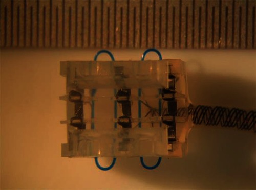
LARSI stimulator with three slot of tripoles. Reproduced with permission.3
Table 1.
Stimulator configurations for an n-tripoles book
| Name | Abbreviation | Number of wires | Figure |
|---|---|---|---|
| Independent between slot - Paired anodes | IP | 2n | 2 (a) |
| Common between slots - Paired anodes | CP | n+1 | 2 (b) |
| Independent between slots - UnPaired anodes | I\P | 3n | 2 (c) |
| Common between slots - UnPaired anodes | C\P | n+2 | 2 (d) |
Fig 2.
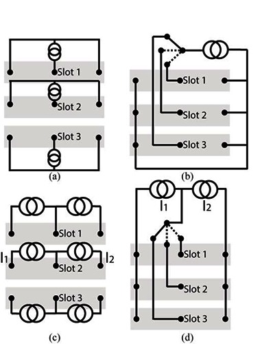
Stimulator configuration for a three slot book - (a) Independent between slots, Paired, anodes (IP); (b) Common between slots, Paired, anodes (CP); (c) Independent between slots, UnPaired, anodes (I\P); (d)
Mathematical Model
To evaluate the electrical potential in the nerve root, a finite element model was built in COMSOL Multiphysics. The equation to be solved is the following, accounting for current conservation,
| (1) |
where V is the electrical potential, and σ̿ the conductivity tensor. Material conductivities are from4. This model is coupled to an ODE (ordinary Differential Equation) system modeling the stimulators electrical circuits (Fig. 3).
Fig 3.
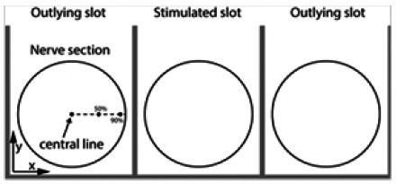
Definition of lines along the nerve where activating function is computed in a nerve section. Highlight of the stimulated/outlying slots.
The activation of nervous fibres inside a root can be evaluated using the Activating Function (AF) [5], i.e.
| (2) |
where d is the diameter of the fibre, pi, the axoplasm resistivity, cm, the membrane capacitance per unit area, Δz, the discretization length of axon, Vi, the electrical potential at z = iΔz, and Ln, the internodal distance. The activating function is a valuable tool to check if an action potential is triggered in a nervous fibre at a specific location. Positive peaks of the AF indicate a depolarization of the membrane, that can lead to the creation of an AP. Inversely, negative peaks indicate hyperpolarization. By defining an arbitrary threshold for the activating function, we evaluate which nervous fibre is active, and at which location an action potential will be fired. The cross-talk ratio (ctr) between nerves is evaluated by computing the ratio between the maximum of the AF along a nervous fibre located on the central line of the nerve being in the slot stimulated and a nerve in an outlying slot (Fig. 3), i.e.
| (3) |
A high ctr indicates a lower likelihood of accidental stimulation of neighboring nerves. The slots of the book electrode are separated by thin sheets of silicone rubber, and the 3 slots are closed by a lid. To evaluate the importance of the lid’s seal, and the impact of current spreading between slots, we computed the ctr for different gaps between the walls of the slot and the lid.
Animal Model
A series of in vitro experiments on the sciatic nerves of Xenopus Laevis were performed.
Female frogs were decapitated and pithed prior to dissection. The sciatic nerves on both sides were exposed, from the spinal cord to the knee (common peroneal branch). A thread was then tied at both ends to avoid losing the axoplasm. The threads were also used to handle the nerves as they should be touched as little as possible to preserve their integrity. From the start of the dissection, the nerves were kept moist with amphibian Ringer solution at room temperature. The same care was taken after removal from the body. The explanted nerves were 80 to 100mm long, with a diameter of 1mm at the spinal end and about half that below the knee. Each experiment spanned two days (one day per nerve) as frog nerves carefully handled and kept in Ringer remain excitable for up to 36 hours.
The nerve was mounted in a two-chamber bath as shown in Fig. 4. Using the precision screws, the tension in the nerve was adjusted to hold it just straight (rather than bowing at the middle) without over-stretching it. On the stimulation side, it was placed in the central slot of a book immersed in Ringer solution. On the recording side, it was resting, in air, on a pair of platinum hook electrodes connected to an amplifier (WorldPrecision ISO-DAM8A, gain set to 100 or 1000) and the signal was displayed on an oscilloscope and recorded. The part of the nerve in air was kept moist with Ringer solution, and care was taken to avoid shorting the hooks with the formation of a drop of solution.
Fig 4.

Experimental setup, for clarity only the central slot is shown (reproduced with permission)3
The current pulses delivered by the experimental stimulator at a frequency of 1Hz were charge balanced. Their shape was rectangular. Their width was adjustable up to nearly 3 ms. The amplitude of the pulse delivered to each anode was controlled. The cathodal current is given by the sum of both anodal currents. The total current amplitude was adjustable with a potentiometer up to 10mA. The current imbalance is calculated as i1/(i1 + i2).
To study the cross-talk threshold, current pulses were sent to the outer slot, and their amplitude increased until compound action potentials from the nerve in the other, passive slot, were recorded at the hook electrodes. Cross-talk ratios were estimated as the ratio of the cross-talk threshold to the direct activation threshold. This was done for all the current imbalances. These tests were repeated on 19 frog nerves.
Result
Mathematical Model
Fig. 5(a) shows AF curves for the CP configuration with perfectly balanced current along three nervous fibres located at the fibre centre, at 50% off-centre, and at 90% off-centre (Fig. 3). The positive peak, indicative of strong depolarization, is at the level of the central cathode. While the two negative peaks are located at the level of the two anodes. Fig. 5(b) shows activating function curves for fibres in a neighboring, non-stimulating, slot. In CP, all external anodes are connected together, hence the hyperpolarization peaks at the level of these electrodes. However, we also observe strong depolarization peaks at the edges of the slot (z = 0 mm and z = 9 mm). These zones, where action potentials are likely to be elicited, are known as virtual cathodes. Virtual cathodes are present at both ends of the peripheral slot.
Fig 5.
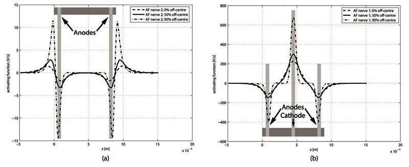
Activating function for nerve fibres at 3 locations inside a nerve. (a) Nerve in active slot. (b) Nerve in peripheral, non-stimulating, slot.
Animal model
Compound Action Potentials (CAP) were elicited in the nerve in the active slot (see Fig. 6) for all current imbalances. CAP were also elicited in the nerve in the adjacent, passive, slot for the least tripolar of the current imbalances. Average cross-talk ratios computed from these measurement are plotted on Fig. 7.
Fig 6.
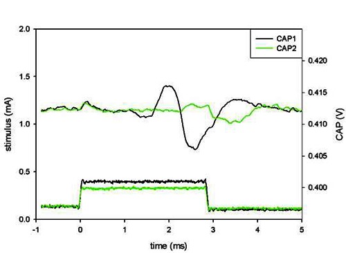
Compound action potential for true tripole (no current imbalance), for a stimulus at threshold (CAP2) and one 16% larger (CAP1). Reproduced with permission3
Fig 7.
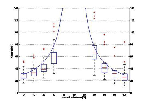
Cross-talk ratio depending of current imbalance for Independent between slots, Unpaired, anodes (IP) - Box plot represent measured data from3 continue line represent simulated data.
Model validation
Fig. 7 shows the cross-talk ratios computed using the mathematical model for the I\P situation (continuous line) and calculated from the sciatic nerve measurement (box plot). The central mark in the box represents the median, the edges are the 25th and 75th percentiles, and the whiskers extend to the most extreme data points not considered outliers. Outliers are represented by crosses.
Influence of leaking book
The results presented here are obtained by opening the lid of the book when the current is perfectly balanced to simulate the effect of a leak in the insulation of the electrode mount. When the lid is perfectly sealed, both configurations have a very different cross-talk ratio (140 for CP and over 3000 for IP). However if a leak is present (lid not well sealed), the cross-talk ratio is radically decreased in both configurations (8 for CP and 12 for IP) even for a very small leak (gap between the lid and the vertical wall = 63 µm).
Influence of central electrode position
The influence of the position of the central electrode on the cross-talk is visible on Fig. 8. The position of the central electrode is described as a relative position in the slot (0% is the location of the first electrode, 50% the normal position, and 100% corresponds to the position of the last electrode).
Fig 8.
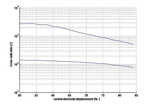
Comparison of cross-talk ratio for electrode displacement for IP (upper curve) and CP (lower curve).
Discussion
Mathematical Model
Figure of the activating function (Fig. 5) show well the direct electrode activation and virtual cathodes present at both end of the slot. This offers a likely explanation for the origin of the cross-talk observed in the patients.
Two facts can be observed on the figures of the activating function:
The amplitude of the activating function of a nervous fibre in the stimulation slot varies almost three times inside the same nerve depending on the depth of its location.
There is cross-talk, even if the current is perfectly balanced: virtual electrodes are present on the nerves not being stimulated.
Our results also show that the smallest depolarization peak is always obtained for the fibre along the centre of the nerve. Hence, if this peak is high enough to trigger an action potential, most fibres in the nerves are likely to be activated. However, this will not be the case if there is a hyperpolarization that blocks the action potential occurring near a real or virtual anode.
Animal Model
Cross-talk was present, however at ratios larger than to those observed in the LARSI patients [2], and only when the current was not balanced. In none of our 19 experiments did we observe cross-talk when the current imbalance was 10% or less.
Model validation
As seen on Fig. 7, the results of the mathematical model are close to those of the animal experiment, validating our mathematical model as an acceptable representation of an in vitro situation. In the future, this mathematical model will be used to model more electrode configurations, causes of current imbalance, and other parameters not easily controlled in an experimental setting.
Influence of leaking book
The results show that care should be taken when sealing the slot as a leak can considerably decrease the crosstalk threshold. This suggests that in the LARSI, where the cross-talk ratio was below 10, there might have been some current spread caused by poor insulation, maybe combined with an imbalance of the current.
A possible reason for this would be an unequal growth of connective tissue, that could have affected the lead seal (as it was not glued in place), and caused the impedance between the electrodes to be considerably different.
Influence of the central electrode position
We have only begun to study the influence of central electrode displacement. A misplacement of the central electrode relative position up to 20% is quite likely for hand-built commercial electrodes. Fig. 8 shows that this would have reduced by three the cross-talk ratio of independent slot with paired anode, but in regards of the high cross-talk ratio for current balanced situation (relative position of 50%), this is not an issue. Reducing the number of wires from 2n to n+1 (IP to CP configuration) increases the cross-talk even if the current is perfectly balanced. However, the cross-talk ratio when the current is perfectly balanced is very high in both configurations. If the current is not balanced, and is due to central electrode misplacement, the decrease of ctr in both configuration is still acceptable. A central electrode misplacement of a few percent is almost negligible for ctr. A leak in the seal, even with balanced current, is much worse with regards to the cross-talk. In conclusion, using a CP configuration (n+1 wires) is acceptable for ctr if the lid is perfectly sealed. Further investigation should focus on other parameters: impedance asymmetry due to contamination of the slot by a material of different conductivity, imperfect geometry of the book, etc.
Acknowledgment
An important part of this study is based on experimental data which are part of the PhD Thesis3 of Anne Vanhoestenberghe. Her knowledge and advice have been determinant to establish the simulations.
Contributor Information
Antoine Nonclercq, Email: anoncler@ulb.ac.be.
Alain Delchambre, Email: adelch@ulb.ac.be.
Anne Vanhoestenberghe, Email: a.vanhoest@ucl.ac.uk.
References
- 1.Troyk PR, Donaldson N, de N. Implantable FES Stimulation Systems: What is Needed? Neuromodulation 2001;4:196–204. [DOI] [PubMed] [Google Scholar]
- 2.Donaldson N, Rushton D, Tromans T. Neuroprostheses for leg function after spinal-cord injury. Lancet 1997;350(9079):711. [DOI] [PubMed] [Google Scholar]
- 3.Vanhoestenberghe A. Implanted Devices: Improved Methods for Nerve Root Stimulation [Doctoral dissertation, University College London, 2008]. [Google Scholar]
- 4.Geddes LA, Baker LE. The specific resistance of biological material - A compendium of data for the biomedical engineer and physiologist. Med Biol Eng 1967;5:271–293. [DOI] [PubMed] [Google Scholar]
- 5.Rattay F. Analysis of Models for Extracellular Fiber Stimulation. IEEE Trans Biomed Eng 1989;36:676–682. [DOI] [PubMed] [Google Scholar]


