Abstract
Hybrid robotic systems represent a novel research field, where functional electrical stimulation (FES) is combined with a robotic device for rehabilitation of motor impairment. Under this approach, the design of robust FES controllers still remains an open challenge. In this work, we aimed at developing a learning FES controller to assist in the performance of reaching movements in a simple hybrid robotic system setting. We implemented a Feedback Error Learning (FEL) control strategy consisting of a feedback PID controller and a feedforward controller based on a neural network. A passive exoskeleton complemented the FES controller by compensating the effects of gravity. We carried out experiments with healthy subjects to validate the performance of the system. Results show that the FEL control strategy is able to adjust the FES intensity to track the desired trajectory accurately without the need of a previous mathematical model.
Key Words: feedback error learning, functional electrical stimulation, stroke, upper limb rehabilitation, hybrid robotic system
Stroke is a leading cause of adult disability around the world. According to the World Health Organization, 15 million people worldwide suffer a stroke each year.1 Motor impairment is a common consequence after a stroke, which impacts the patients’ quality of life (e.g. loss of motor function and control) negatively. Rehabilitation therapy plays an essential role in the patients’ recovery. However, after completing conventional treatments, many patients are left with limited reaching and grasping capabilities. It has been shown that functional electrical stimulation (FES) has a positive effect for rehabilitation of upper limb motor functions in the stroke population.2,3 Furthermore, it has been reported that the use of FES aids to preserve and restore muscle mass and its function after a period of reduced activity,4 as well as to stimulate cortical reorganization after the neurological injury.5 However, the non-physiological motor unit recruitment, the lack of muscle selectivity, and the need of a large amount of power to support the arm during reaching movements hinder the wide use of FES technologies in clinical settings. Of relevance in this study, these drawbacks prevent the proper assistance of reaching movements accurately in unconstrained spaces and they generally lead to a fast and accentuated occurrence of muscle fatigue. Hybrid approaches, combining FES with robotic devices have emerged over the last years as a way to overcome these limitations, and to generate a more robust and natural solution for rehabilitation.6 The design of robust FES controllers is an important part of such systems. The limited time available during clinical trials makes it desirable that systems present simple designs with minimum parameters to be set up. Freeman et al.7 presented the use of the iterative learning control (ILC) algorithm to control the arm response when using FES for reaching rehabilitation. This strategy allows the adjustment of FES intensity based on the resulting tracking error of previous movements. However, the approach requires a mathematical description of the musculoskeletal system. Due to the high complexity of such system and the simplifications typically assumed to derive the models, the applicability of these approaches for clinical purposes is limited. Additionally, there is a need to determine a large number of parameters, which represent a time-consuming and difficult to reproduce task in a clinical environment. Kawato, 19908 proposed the Feedback Error Learning (FEL) scheme, which describes how the central nervous system acquires the internal models of the body. In this scheme, the motor control command of a feedback control loop is used to train a feedforward model that learns to anticipate the motor output command. This approach can be implemented using a neural network (NN) to learn the inverse dynamic of the controlled system, taking the output of a conventional feedback controller as a training signal. The main advantage of this strategy compared to similar approaches (e.g. ILC) is that the system does not require an explicit model of the controlled system and only requires a few parameters to work correctly. This results in a simple approach that is easy to deploy in clinical settings. Previous studies showed that the FEL scheme can be used to control the hand and leg motion with FES.9–11 However, this control strategy has never been tested in a hybrid system for rehabilitation of reaching movements. The main objective of this paper is to present the design and the implementation of the FEL controller to guide the movement of the shoulder and elbow joints with FES. The controller is used in a simple hybrid robotic system, complementing the FES assistance with a passive exoskeleton to compensate the effects of gravity.
Material and Methods
System overview
Typically, stroke patients suffer from an over-activity of flexor muscles of the arm and activity loss in the triceps, anterior deltoids and finger extensor muscles12. This is why the present system focuses on aiding users to move their paretic arm towards distal directions in 3D space. The general overview of the developed hybrid rehabilitation system is shown in Figure 1. The principal components of the system are the assistive devices (upper limb exoskeleton and FES device), the High-Level Controller (HLC) and the configuration interface. The hybrid assistance is given by the upper limb exoskeleton, Armeo Spring® (Hocoma, Switzerland), and the IntFES stimulator (Technalia, Spain). The stimulator generates biphasic electrical pulses and allows stimulating in a frequency range from 1 to 400 Hz, with pulse amplitudes from 1 to 50 mA and pulse widths from 50 to 1000 us. The HLC is implemented in a PC104 architecture running under the xPC Target® operating system (The MathWorks Inc.) for real-time operation. This component estimates the arm joint location, generates the reference trajectory and executes the FES control algorithm. Finally, a dedicated computer acquires the joint angles of the exoskeleton and it sends this information to the HLC. Also, it allows the configuration of the therapy parameters (e.g., maximum FES intensity, range of movement, arm trained, etc.).
Fig 1.
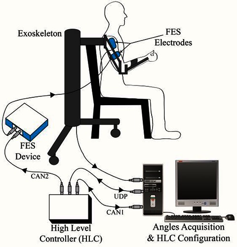
A General overview of the hybrid robotic system for reaching rehabilitation.
Fes controller
Human Arm
We approximated the position of the human arm joints using the rotation axes of position transducers embedded in the exoskeleton by considering several assumptions. First, we assumed a parallel arrangement of the human arm with the exoskeleton (Figure 2A). Second, we assumed that stimulation of the triceps produces a moment about an axis orthogonal to both the forearm and the upper arm and stimulation of the anterior deltoids produces a moment about an axis fixed with respect to the shoulder. Therefore, the same objective transformation as the one used in12,13 was implemented to determine the arm axes (shoulder and elbow) and define their positions given by the vector Ø = [Ø1, Ø2, Ø3, Ø4, Ø5] (see Figure 2B).
Fig 2.
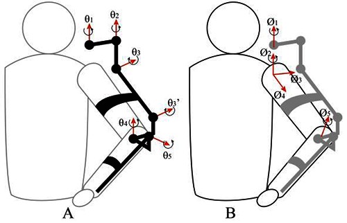
A) Exoskeleton joint axes rotation; B) Human arm joint axes rotation.
Feedback Error Learning based controller
We considered that the controlled system is composed of two single-input, single-output (SISO) system. Thus, the movement of the forearm and upper arm are independent of each other. This consideration allows us to implement two independent FEL controllers, one for each joint. Each controller consisted of a proportional-integral-derivative (PID) feedback controller combined with feedforward control based on a neural network (NN), as shown in Figure 3. The controlled system was underactuated since the assistance was applied only at the Ø2 and Ø5 axes. As was stated in12,13, the freedom of movement in the remaining joints (Ø1, Ø3, and Ø4) yields a more natural movement response.
Fig 3.
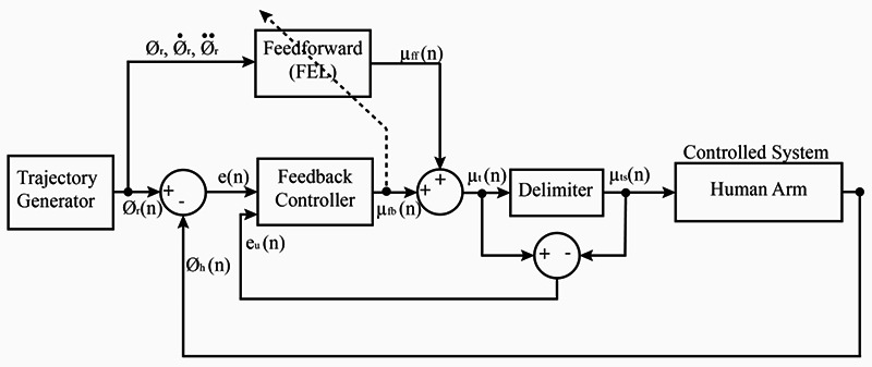
Functional electrical stimulation (FES) control scheme. Block diagram of the implemented feedback error learning controller for single joint. Ør is the reference trajectory, Øh is the measured joint angle corresponding to the anterior deltoid or triceps axes, Tf is the torque generated at the musculoskeletal system due to the FES, Th is user voluntary contribution to movement and Tg is the contributed torque for arm weight compensation.
The input for the feedback loop was the desired position profile while the input for the feedforward loop was the desired position, velocity and acceleration profiles. Positive output values of the controller generated muscle motor unit activations while negative values were ineffective and could lead to windup the integral term of the feedback controller. However, negative values were required for the FEL to learn. Therefore, we implemented a delimiter that prevented the integral windup. The PID constant parameters were adjusted using the Ziegler and Nichols method, taking the average movement responses in healthy subjects.
Feedforward learning controller
The implemented feedforward loop of the FEL controller learned the nonlinear inverse dynamic of the musculoskeletal system by receiving as input the desired kinematic profile and using the output of the feedback loop as the correction parameter8. This learning process was kept along the execution of each movement and the output of the feedback loop tended to zero as the learning proceeds evolved. The NN was defined as a three-layer perceptron network. This network relied on nine input, nine hidden nodes, and one output node. The input and hidden layers had an additional bias node (value -1). The kinematic data used for the NN was calculated beforehand, and it was normalized in the range of -1 to 1 to generate faster learning rates. The NN was trained using the gradient descent algorithm.14 The NN weights were initialized with small random values close to zero, which were updated during the movement executions at each sample time.
Reference Generator
To generate the tracking references, we used the method described by Flash and Hogan.15 They derived a mathematical expression that describes the way in which the central nervous system moves the hand smoothly from one point to another. They called this function the minimum jerk trajectory, and it only requires the target and the duration of the desired position to describe the trajectory completely. Robotic rehabilitation systems like the MIT-Manus and Arm Guide have also used this function as reference.16 In this experiment, we generated the profiles for the position, the velocity, and the acceleration.
Experiment Settings
Seven healthy subjects participated in the study. They gave their informed consent to take part in the experiment. Subjects were asked to execute a set of twelve movements. They were instructed to keep their arms passive, without making any voluntary effort, while the FES activated the target muscles (anterior deltoids and triceps). The ArmeoSpring was adjusted according to the subjects’ arm lengths. The level of support was regulated such that their arm was kept about their thigh in the horizontal plane. Surface electrodes (Pals platinum - rectangle 5x5) were attached to the anterior deltoids and triceps muscles. The maximum pulse amplitude was determined by increasing gradually the current of the stimulator, with a fixed pulse width of 450 μs, until a comfortable motor response was observed. The FEL control modified the pulse width of the stimulation during movement execution to adjust the level of assistance. The pulse width was modulated in the range of 50 to 450 µs. To define the maximum range of movement and determine the target position, we applied the maximum electrical stimulation intensity simultaneously to both muscles and recorded the resulting movement. After analyzing the recording data, the target position was defined as the maximum articular angle achieved at each joint (shoulder and elbow). These maximum angles were used in the minimum jerk function to generate the reference trajectory. In all trials, a period of three seconds was used to drive the arm from the starting position to the target.
Results
To analyze the actuation control signal of the FEL controller, we calculated the power ratio (PR) between the feedforward and the feedback controllers across trials. The PR was defined as the relation between the squared value of the stimulation intensity (output power) of the feedforward or at the feedback loop, and their sum. This analysis allows us to evaluate the learning rate since the feedforward controller should produce the full actuation command to drive the movement once the inverse dynamic model of the controlled system has been learned. The first row of Figure 4 shows the PR for the feedback (Ufb) and feedforward (Uff) controllers for the shoulder (Ø2) and elbow (Ø5) joints. It is shown that from the fourth trial, the assistance is almost given entirely by the feedforward controller in both cases. The second analysis relies on the calculation of the root mean square (RMS) error for each trial. Figure 5 depicts the evolution of the RMS error for each participant (n=7) during the execution of the twelfth trial. Here, the black line represents the average RMS error for all subjects, and the shaded area is the width of the standard deviation with respect to the average. It is observed that, for both joints, the error was reduced as the number of executed tasks increased. This points out that the FEL algorithm can learn the dynamic of the movements, resulting in enhancements of the tracking accuracy. Figure 6 shows the joints (shoulder -left- and elbow – right-) tracking accuracy during the first, fourth and twelfth movement execution. This result shows that after the fourth trial execution, the trajectory error (row 2) was significantly decreased in both joints (blue and green lines). However, the difference between the fourth and twelfth trials is smaller. This is in agreement with Fig. 5, where the first movements present a bigger slope in the learning curve. As learning proceeds, the corresponding slope flattens resulting in the final learned model. In regards to the actuation signal, Figure 7 depicts that in the first movement, most of the output is given by the feedback loop (row 1, red line). However, after the learning process, the output is mainly due to the learned model (row 2 and 3, blue line). At this point, the feedback loop is only compensating for small disturbances in the movements. This compensation causes a ripple in the output, as shown in the figure. However, lowering the gains of the PID controller can effectively reduce this ripple.
Fig 4.
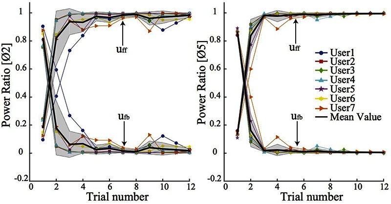
Evolution of the Power Ratio (PR) for the control action of the feedback (ufb) and feedforward controllers (uff). The left plot illustrates the PR index at the shoulder joint (Ø2) while the right represents the result for the elbow joint (Ø5)
Fig 5.
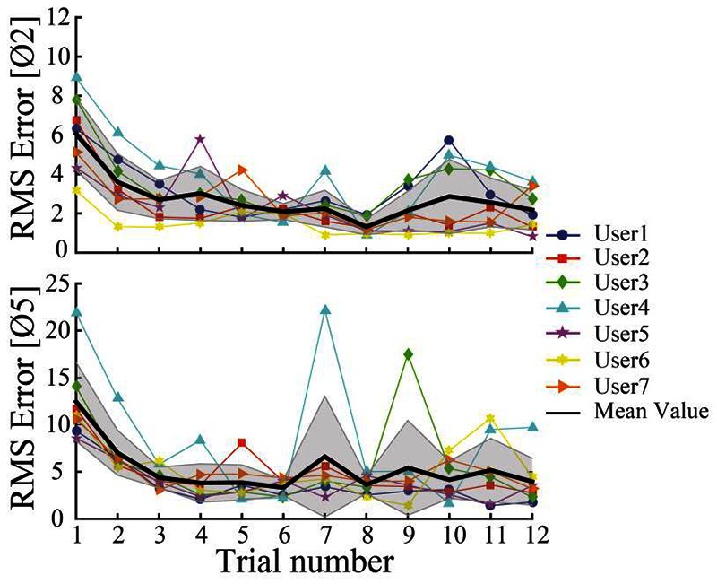
Evolution of the root mean square error over the execution of the trial for the shoulder (Ø2) and elbow joints (Ø5).
Fig 6.
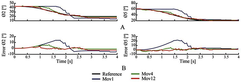
An example of the controller performance for participant 1. A) Tracking accuracy during trial 1 (blue), trial 4 (green) and trial 12 (red) for shoulder (left) and elbow (right) joints; B) Error trajectory of each trial (1 - blue-, 4 -green- and 12 –red-).
Fig 7.
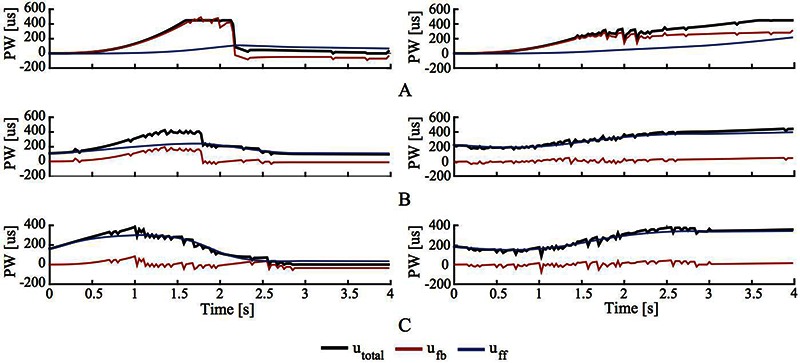
A), B) and C) The output of the FEL controller during the first, fourth and twelfth movement execution respectively for the shoulder (left) and elbow (right) joints; black: total actuation signal; red: actuation given by the feedback loop; blue: actuation signal given by the feedforward loop
Discussion
We have implemented a FES controller based on the Feedback Error Learning (FEL) scheme to assist a reaching movement. We combined this controller with a passive exoskeleton into a simple hybrid robotic system setting. The controller adjusted dynamically the FES at the shoulder and elbow simultaneously to track the desired trajectory. The FEL algorithm was able to learn the inverse dynamic of the system and reduced the error within acceptable ranges. This controller is very attractive to use in clinical environments since it achieves good accuracy in tracking a movement without needing a mathematical description of the musculoskeletal system of the patient. Also, it only needs a few parameters to work. Furthermore, due to its learning capabilities, this controller could be implemented in a full hybrid robotic system with an active exoskeleton. Usability tests with stroke patients will be addressed in future work. These tests will verify the capability of the controller to learn the inverse dynamics and adjust the level of assistance when spasticity and other alterations due to stroke are present.
Acknowledgment
This work has been done with the financial support of the Ministry of Science and Innovation of Spain, project HYPER (CSD 2009-00067 Hybrid Neuroprosthetic and Neurorobotic Devices for Functional Compensation and Rehabilitation of Motor Disorders). This paper was presented at the 20th International Functional Electrical Stimulation Society (IFESS) Conference, 2016 June 8-10, Grande-Motte, France.
Contributor Information
Jose Gonzalez-Vargas, Email: je.gonzalez@csic.es.
Jaime Ibáñez, Email: jaime.ibanez@csic.es.
Fernando Brunetti, Email: fjbrunetti@gmail.com.
José Luis Pons, Email: jose.pons@csic.es.
References
- 1.Mackay J, Mensah GA, Mendis S, Greenlund K. The atlas of heart disease and stroke. World Health Organization; 2004. [Google Scholar]
- 2.Popovic MR, Thrasher TA, Zivanovic V, Takaki J, Hajek V. Neuroprosthesis for retraining reaching and grasping functions in severe hemiplegic patients. Neuromodulation 2005;8:58–72. doi:10.1111/j.1094-7159.2005.05221.x. [DOI] [PubMed] [Google Scholar]
- 3.Hara Y. Rehabilitation with Functional Electrical Stimulation in Stroke Patients. Int J Phys Med Rehabil 2013;01:1–6. [Google Scholar]
- 4.Maffiuletti NA. Physiological and methodological considerations for the use of neuromuscular electrical stimulation. Eur J Appl Physiol 2010;110(2):223–4. doi:10.1007/s00421-010-1502-y. [DOI] [PubMed] [Google Scholar]
- 5.Thompson AK, Stein RB. Short-term effects of functional electrical stimulation on motor-evoked potentials in ankle flexor and extensor muscles. Exp Brain Res 2004;159:491–500. doi:10.1007/s00221-004-1972-4. [DOI] [PubMed] [Google Scholar]
- 6.Del-Ama AJ, Koutsou AD, Moreno JC, et al. Review of hybrid exoskeletons to restore gait following spinal cord injury. J Rehabil Res Dev 2012;49:497. [DOI] [PubMed] [Google Scholar]
- 7.Freeman CT, Rogers E, Hughes AM, et al. Iterative Learning Control in Health Care: Electrical Stimulation and Robotic-Assisted Upper-Limb Stroke Rehabilitation. IEEE Control Syst 2012;32(1):18–43. doi:10.1109/MCS.2011.2173261. [Google Scholar]
- 8.Kawato M. Feedback-error-learning neural network for supervised motor learning. Adv neural Comput 1990;6:365–72. [Google Scholar]
- 9.Kurosawa K, Futami R, Watanabe T, Hoshimiya N. Joint Angle Control by FES Using a Feedback Error Learning Controller. IEEE Trans Neural Syst Rehabil Eng 2005;13:359–71. [DOI] [PubMed] [Google Scholar]
- 10.Watanabe T, Fukushima K. An Approach to Applying Feedback Error Learning for Functional Electrical Stimulation Controller: Computer Simulation Tests of Wrist Joint Control. Adv Artif Neural Syst 2010;2010:1–8. doi:10.1155/2010/814702. [Google Scholar]
- 11.Koike Y, Gonzalez J, Gomez J, Yu W. Implementing Feedback Error Learning for FES control. In: 2011 4th International Conference on Biomedical Engineering and Informatics (BMEI) IEEE; 2011. doi:10.1109/BMEI.2011.6098623. [Google Scholar]
- 12.Lum PS, Burgar CG, Shor PC. Evidence for improved muscle activation patterns after retraining of reaching movements with the MIME robotic system in subjects with post-stroke hemiparesis. Neural Syst Rehabil Eng IEEE Trans 2004;12(2):186–194. [DOI] [PubMed] [Google Scholar]
- 13.Cai Z, Tong D, Meadmore KL, et al. Design & amp; control of a 3D stroke rehabilitation platform. 2011 IEEE Int Conf Rehabil Robot 2011:1–6. doi:10.1109/ICORR.2011.5975412. [DOI] [PubMed] [Google Scholar]
- 14.Freeman CT. Upper Limb Electrical Stimulation Using Input-Output Linearization and Iterative Learning Control. Control Syst Technol IEEE Trans 2014;99:1 doi:10.1109/TCST.2014. 2363412. [Google Scholar]
- 15.Marsland S. Machine learning: an algorithmic perspective. CRC press; 2015. [Google Scholar]
- 16.Flash T, Hogan N. The coordination of arm movements: an experimentally confirmed mathematical model. J Neurosci 1985;5:1688–1703. doi:4020415. [DOI] [PMC free article] [PubMed] [Google Scholar]
- 17.Huang VS, Krakauer JW. Robotic neurorehabilitation: a computational motor learning perspective. J Neuroeng Rehabil 2009;6:5. [DOI] [PMC free article] [PubMed] [Google Scholar]


