

1 Background
Orthopaedic residency training is in the midst of a paradigm shift. In 2012, the Residency Review Committee (RRC) for Orthopaedic Surgery and the American Board of Orthopaedic Surgery (ABOS) mandated that there must be structured motor skills training for first-year residents1. Taking from other disciplines such as laparoscopic surgery, surgical simulators have emerged as the tools by which first-year orthopaedic residents can practice and acquire these motor skills. However, in a 2011 national survey of program directors and residents, it was shown that one of the greatest barriers to training residents was cost2. This study further showed that most programs would only be able to afford a simulator costing between $1000 and $15,000. This is a contrast to many virtual reality simulators currently available, which can easily cost upwards of $100,000.
In its mandate, the ABOS also defined a set of core competency skills for a surgical resident to acquire. One such skill is wire navigation, where a surgeon uses fluoroscopic imaging to guide the placement of a wire in bone. This common technique covers many areas of orthopaedic surgery.
Given the new environment in orthopaedic skills training, this project was focused on developing a more affordable surgical simulator that could provide high fidelity training for the task of wire navigation. We specifically targeted the task of placing a k-wire in the treatment of a hip fractures because it is a task that all residents are exposed to during residency. The goal of our simulator was to provide simulated x-ray images of a real k-wire as it is placed into an artificial bone.
2 Methods
The wire navigation simulator (Fig. 1) has six main components: a single camera interfaced with a Raspberry Pi (a credit-card sized computer), a series of three mirrors, a surrogate femur, a guide wire driver, a laser etched guide wire, and a laptop. The camera and mirrors are used to acquire stereo images of the guide wire as the user (resident) places the wire in the surrogate femur. A stream of images are acquired on the Raspberry Pi and transferred over ethernet to the laptop. When a resident requests an x-ray image, the most recently transferred stereo images are grabbed by a MATLAB program, and image processing/analysis is performed on these images. Once the image analysis is completed, the laptop screen displays an artificial x-ray image to the user, showing where the wire is relative to the surrogate femur.
Fig. 1.
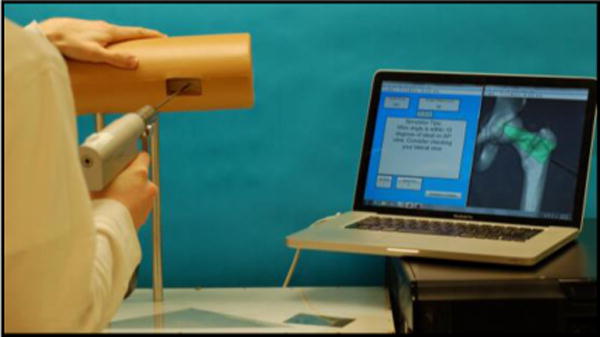
The simulator prototype is shown here. A skin-like sleeve surrounds the surrogate femur to occlude the geometry of the femur from the resident. The Raspberry Pi camera and mirrors are hidden from the user beneath an acrylic surface.
The image processing/analysis proceeds in four main steps: gross edge detection, image cropping and enhancement, pattern matching, and point-to-point registration (Fig. 2). In the first step, the algorithm finds the edges of the wire within an image. The camera is positioned relative to the surrogate femur so that the wire is at the focal point of the camera across a working volume near the femur, while background objects remain out of focus. A gaussian filter is applied to each image to ensure that remaining background noise is blurred, and then a Canny edge detector is applied to the image. A Hough algorithm finds the best-fit position for lines that describe where the wire is located in each image.
Fig. 2. A flow of the pattern matching sequence.
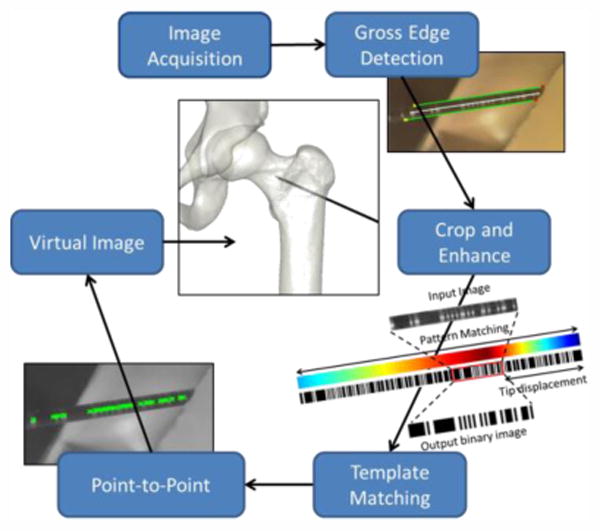
Once the edges of the wire have been found, the image is cropped and rotated so that the wire is completely isolated and horizontally positioned. An adaptive histogram equalization algorithm is applied to the cropped image to enhance the contrast of the etched pattern on the wire and to reduce the effect of any dark or bright patches.
With the wire isolated, images are run through a pattern-matching algorithm. The wire is etched with a binary encoded pattern so that each section of wire has a unique address. The algorithm uses a normalized cross correlation to find where the section of imaged wire best matches along the entire wire pattern. This is a critical step because it gives two key pieces of information; how far the tip of the wire is from the imaged section and a binary image of the wire that can be used to find corresponding points in each image.
A Canny edge detector is applied to the binary images, creating an edge image that marks the start and end of vertical black lines on each wire. These lines represent feature points used to reconstruct the wire vector in 3D space. Subsets of points from the each stereo image are put into a Direct Linear Transform algorithm that uses the 2D points from both images to calculate their 3D position relative to the surrogate bone. The algorithm samples subsets of feature points until a best-fit 3D vector has been found. Using this vector and the tip offset information gained during the pattern-matching step, an artificial x-ray image is created, showing the trajectory and position of the wire relative to the femur (Fig. 3).
Fig. 3.
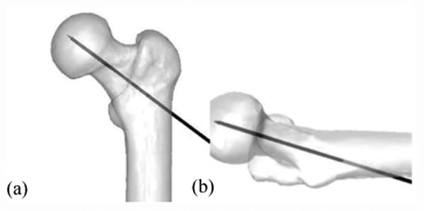
An artificial x-ray displays the wire in bone. Both anterior-posterior (a) and lateral (b) images are available.
Given that this simulator relies on image processing, lighting and background conditions can play a major role in its performance. To test the simulator performance, it was taken to six locations around the University of Iowa campus and run through an array of expected user interactions. Locations were chosen so that it could be exposed to a variety of lighting conditions. At each location, wires were placed into the bone and imaged, as if a resident were using it. The test was deemed successful if the image processing produced an image that a user would accept as true and a failure if the reconstructed image appeared incorrect. In the case of a failed reconstruction, it is very obvious to the user that the wire position shown is incorrect (errors of multiple centimeters).
The accuracy of the simulator was also assessed, by placing the wire at known positions and comparing the projected tip location to the known location. These tests were done in a controlled environment optimized for performance.
3 Results
In testing the performance of the simulator, 491 reconstructions were performed across the 6 different locations (Table 1). Of these cases, 9 were deemed as failed reconstructions, a success rate of roughly 98%. During these reconstructions, the time to display an x-ray varied from 1.75 to 3 seconds. Longer delays occur when there is an initial error in pattern matching and further internal checks must be used to correct for these errors. The accuracy of the simulator was found to be between 0.5 and 1.3mm of error.
Table 1. Simulator performance across varied locations.
| Location | Trials | Failures | Percent Fail |
|---|---|---|---|
| Office | 111 | 1 | 1 |
| Office Bright | 98 | 4 | 4.1 |
| Commons | 90 | 2 | 2.2 |
| Commons Bright | 50 | 1 | 2 |
| Library | 61 | 1 | 1.6 |
| Photo booth | 61 | 0 | 0 |
| Total | 471 | 9 | 1.9 |
4 Interpretation
Although the simulator can at times produce a reconstruction that incorrectly displays the wire location, we have shown that this happens less than 2% of the time across a variety of environments. The results in a photo booth location suggest that by more fully controlling the lighting conditions, all of the failures could be avoided. However, this would come at the cost of a more complicated design. For the majority of requested x-rays, the wire tip location was found with an accuracy that is more than sufficient for training residents. Future work will involve training residents with this simulator and demonstrating how residents can improve on this task through simulated practice.
This project has successfully achieved its goal of developing a high fidelity surgical simulator that can be used to train orthopaedic residents on the task of wire navigation. It uses the same tools that are used by surgeons in the OR which is a large advantage over many of the haptic feedback virtual reality trainers commercially available today. By using readily available raw materials, the cost of constructing a single simulator was kept low, around $500. Not accounting for the intellectual cost of developing the image processing algorithms, this simulator would certainly fall within the limits of a residency training budget as suggested in the 2011 national survey. While the initial focus of development was on hip wire navigation, this setup could easily be applied to other applications, allowing residents to practice a wide variety of guide wire placement tasks.
Acknowledgments
This work was partially supported by grants from the Orthopaedic Research and Education Foundation, the American Board of Orthopaedic Surgery, and the Agency for Healthcare Research and Quality.
Contributor Information
Steven Long, Department of Orthopaedics and Rehabilitation, 2181 Westlawn, The University of Iowa, Iowa City, IA 52242.
Geb W. Thomas, Department of Mechanical and Industrial Engineering, 2404 Seamans Center for the Engineering Arts and Sciences, The University of Iowa, Iowa City, IA 52242
Donald D. Anderson, Department of Orthopaedics and Rehabilitation, 2181 Westlawn, The University of Iowa, Iowa City, IA 52242
References
- 1.ACGME. Orthopaedic surgery requirements. [2015 Oct 26]; http://www.acgme.org/acgmeweb/tabid/140/ProgramandInstitutionalAccreditation/SurgicalSpecialties/OrthopaedicSurgery.aspx.
- 2.Karam MD, Pedowitz RA, Natividad H, Murray J, Marsh JL. Current and future use of surgical skills training laboratories in orthopaedic resident education: a national survey. J Bone Joint Surg Am. 2013 Jan 2;95(1):e4. doi: 10.2106/JBJS.L.00177. 2013. [DOI] [PubMed] [Google Scholar]