Abstract
We report the development and use of MRI-compatible and MRI-visible 3D printed models in conjunction with advanced visualization software models to plan and simulate safe access routes to achieve a theoretical zone of cryoablation for percutaneous image-guided treatment of a C7 pedicle osteoid osteoma and an L1 lamina osteoblastoma. Both models altered procedural planning and patient care. Patient-specific MRI-visible models can be helpful in planning complex percutaneous image-guided cryoablation procedures.
INTRODUCTION
Percutaneous image-guided thermal ablation of tumors in the posterior spinal elements is difficult as these tumors often abut major neural structures including the nerve roots, dura, and spinal cord. Neurological damage and cerebrospinal fluid (CSF) leak have both been reported (1,2). Three-dimensional (3D) pre-procedure planning and simulation may enhance procedure safety and efficacy. Also known as additive manufacturing or rapid prototyping, 3D printing has been utilized for pre-procedure planning in many areas including endovascular aneurysm repair and many types of surgery (3–5). It has also been utilized for spine surgery simulation (6–8). We have created CT- and MRI-visible models of a cervical osteoid osteoma and a lumbar osteoblastoma and then used those models in conjunction with advanced visualization techniques to plan and simulate percutaneous MRI-guided spine tumor cryoablation.
MATERIALS AND METHODS
This study was approved by our institutional review board and performed in compliance with HIPAA. Patients were consented for the in vivo procedures according to standard institutional protocol. The need for patient informed consent was waived for the research component involving the development of 3D models and procedure simulation.
Patient 1 was a 17 year-old male with a C7 right pedicle osteoid osteoma status post partial cryoablation. The lesion was only partially ablated because the most anteroinferior aspect of the tumor was at the periphery of the ablation zone and the probe could not be repositioned without ice ball extension into the thecal sac. Due to residual persistent pain, we developed a CT-visible, MRI-compatible, and MRI-visible 3D printed phantom to determine whether there was a viable percutaneous approach that would enable safe cryoablation of the residual lesion.
Raw data from the patient’s most recent cervical spine CT was reconstructed at 1 mm isotropic voxel resolution. Segmentation with isolation of bone and tumor was performed using Vitrea 6.7 (Vital Images, Inc., Minnetonka, MN). The segmentation was exported as a Stereolithography (STL) file format and post-processed with 3-matics (Materialise NV, Leuven, Belgium) computer aided design (CAD) software to optimize for printing (remeshing, smoothing and trimming).
The model was printed on an Objet 500 Connex printer (Stratasys, Eden Prairie, MN) with a material that has been newly identified as possessing an MR signal (Objet RGD525 High Temperature, Stratasys), likely due to a small proportion of petroleum product in the resin formulation (9). An MR-visible 3D printing material was not previously known and thus simulation was not an option at the time of this patient’s initial cryoablation, which was also performed by us. Print time for the particular printing technology used (material jetting) is dependent on a number of factors including the desired printing resolution, the specific printing material used, and whether multiple models are printed together. The print time for this particular model was 12.5 hours. Were this model printed on the same printer but using a different material (Vero White, Stratasys), the print time would have been 4.5 hours due to differences in the time required to relieve the internal stresses in the printed parts between the printing of each layer. The cost of printing this model was $437, including overnight shipping (R&D Technologies, North Kinston, RI). The planned procedure was simulated on the 3D printed model in our combined CT and MR procedure suite. The model was placed in a position similar to that expected for the patient’s spine and the radiologist performed the procedure under sterile conditions. Drilling was performed under CT guidance with a Siemens Biograph mCT 64 PET-CT System (Siemens Medical Solutions, Malvern, PA). Following drilling, the same type of cryoprobe to be used in the actual procedure (17-gauge IceSeed, Galil Medical, Minneapolis, MN) was advanced to the anterior aspect of the visible lesion. The model was then transferred to the MRI scanner and the cryoablation ice ball size and location was monitored with a Siemens 3-Tesla MAGNETOM Verio MRI System (Siemens Medical Solutions, Malvern, PA). The simulated procedure took approximately 90 minutes. The in vivo procedure was performed in the patient the following day, approximately 9 months after the initial cryoablation, by the same radiologists (NH and TL) who performed the both initial cryoablation and the simulation, and with identical technique to the simulation (Figure 1). The in vivo procedure took approximately 7.5 hours from first CT image to final MRI image with an intraprocedural delay of approximately 2 hours due to a technical malfunction of the MRI scanner. Of note, at our institution we typically monitor spine cryoablation with MRI, which enables visualization of the ice ball and proactive manipulation of the argon flow rate to avoid ablation of adjacent nerves and of the thecal sac without the necessity of adjuvant thermoprotective techniques.
FIGURE 1.
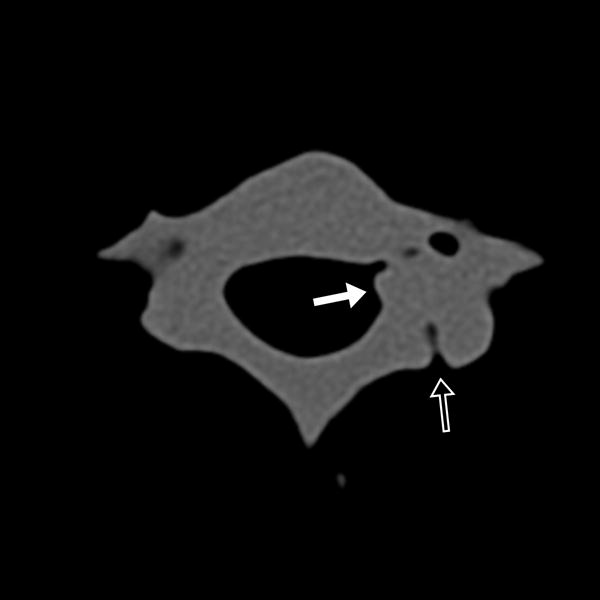
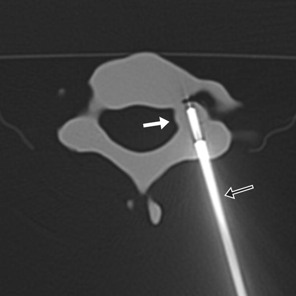
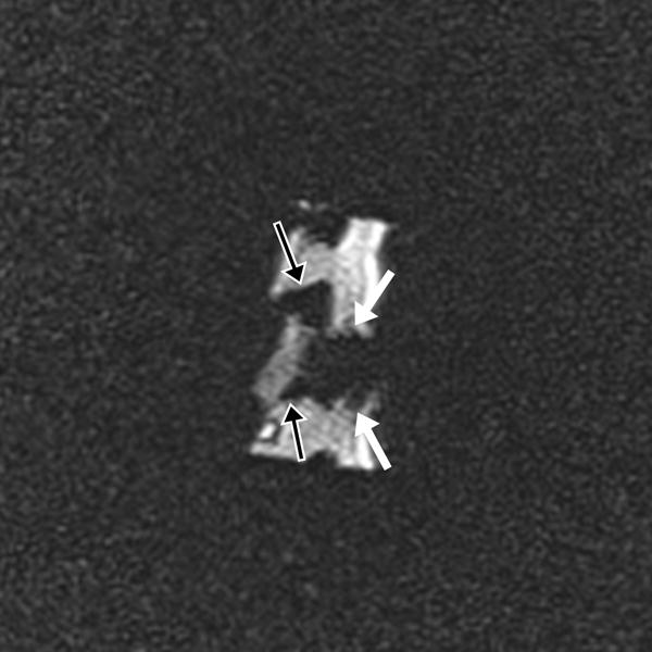
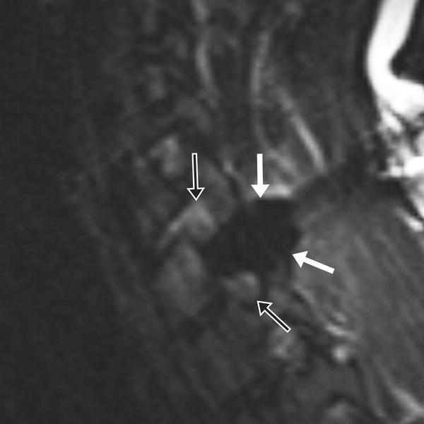
17-year-old male with C7 osteoid osteoma. (a) Axial CT image of the model demonstrates the tumor (white arrow) and prior ablation needle tract (black arrow). (b) Axial CT image of the model with the cryoprobe (black arrow) positioned within the tumor (white arrow). Sagittal T2 weighted TSE MR images of the (c) model and (d) patient, with the model rotated slightly clockwise relative to the patient but otherwise in similar plane, demonstrate the ice ball (white arrows) encompassing the entire tumor and sparing the neural foramina (black arrows).
Patient 2 was a 22 year-old male with an L1 left lamina osteoblastoma also status post partial cryoablation. The L1 lesion was only partially ablated due to a conservative approach taken to ensure the safety of the adjacent nerve root. Given the utility of the 3D model in Patient 1, a similar model was created of the L1 tumor and a similar sequence of events was followed. Printing of this model took 15.5 hours and cost $819 including overnight shipping (R&D Technologies, North Kingston, RI). The simulated procedure took approximately 90 minutes. In addition, due to a high likelihood of procedure failure identified during the simulation, as described in the results section, advanced 3D visualization models were created to explore alternative ablation approaches. Specifically, 3-matic CAD software (Materialise NV, Leuven, Belgium) was used to simulate an approximately ellipsoidal 3 × 2 cm cryoablation zone, the maximum anticipated size of a safe cryoablation zone in this case (the manufacturer-supplied specifications of the iceball shape for this cryoprobe by laboratory testing in gel are 2.0 × 2.7 cm for −20C and 3.3 × 3.8 cm for 0C; in vivo sizes are typically smaller and we dynamically adjust the growth of iceballs in vivo by titrating cryoprobe flow rate and freeze times). Simulated ablation zones were placed in multiple orientations, and the tract necessary to achieve each zone was simulated with a thin cylindrical shape. The in vivo procedure was performed the following day, approximately 9 months from the initial cryoablation, by the same radiologists (NH and TL) utilizing an approach identified with the 3D software models (Figure 2). The in vivo procedure took approximately 5 hours from first CT image to final MRI image.
FIGURE 2.
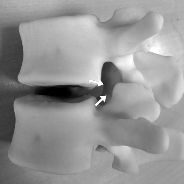
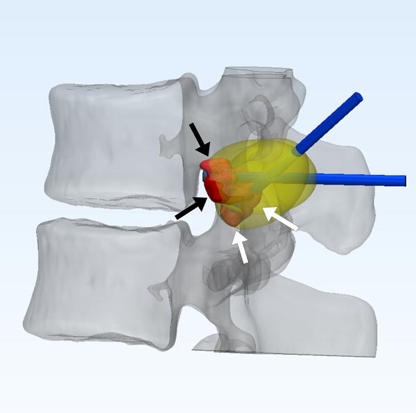
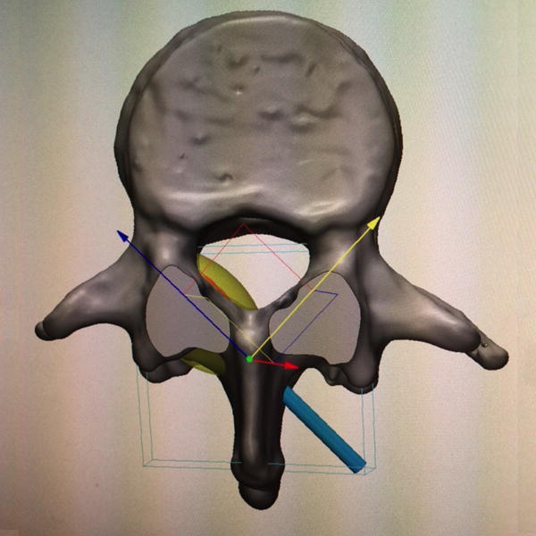
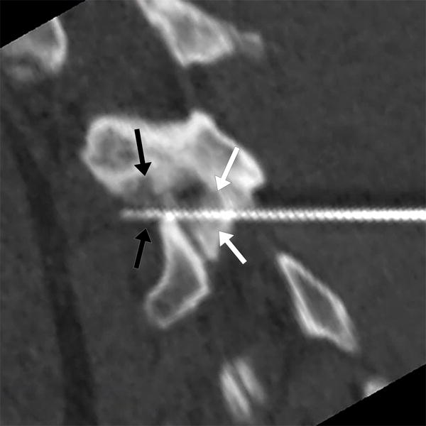
22-year-old male with L1 osteoblastoma. (a) 3D printed model, printed with CT- and MR-visible material for simulation of a dual-tract approach, demonstrates the inferior palpable tumor lobule (white arrows). (b) Advanced 3D visualization software model developed prior to the in vivo procedure displays the residual tumor lobules inferior (white arrows) and deep (black arrows) to the ablated tumor nidus with the cryoprobe tracts (blue arrows) and theoretical ablation zones (yellow volumes) as performed during the model simulation. (c) Advanced 3D visualization software model developed prior to the in vivo procedure displays theoretical contralateral single-tract approach that allowed simultaneous ablation of both lobules (blue/blue arrow indicating direction of cryoprobe, yellow volume indicating projected ice ball contour). Although the modeled ice ball contour appears to invade the expected thecal space, CSF flow was expected to decrease the size of this component of the ice ball in vivo. This approach was utilized in the actual in vivo procedure the next day, the ice ball was carefully monitored, and there was no ice ball extension into the thecal sac. (d) Reconstructed sagittal double oblique CT image, with the posterior aspect of the patient conventionally oriented at the left of the image, demonstrates the residual tumor lobules inferior (white arrows) and deep (black arrows) to the ablated tumor nidus. The cryoprobe is positioned through both of these residual lobules.
RESULTS
Prior to viewing the 3D model, we planned to enter the C7 posterior elements more superiorly than during the first ablation to enable a steep approach for easy positioning of the cryoprobe tip within the residual tumor. The 3D model demonstrated that the residual cortical defect from the initial C7 ablation was not only patent and accessible, but more prominent and deformed than was appreciated on the individual 2D CT slices. The extent of this deformity, likely in part due to slow healing from partial ablation of the tract, generated concern that creating a second cortical hole would decrease osseous integrity and result in subsequent posterior element fracture. As a result, we decided to use the simulation as a test to determine whether the residual lesion could be adequately targeted through the initial cortical hole. To that end, the initial cortical hole was used for access during the simulation, a new more angulated tract was drilled through the model medullary tissue, and the cryoprobe tip was advanced to the anterior edge of the residual tumor. The same approach was taken in vivo the following day. An ice ball covered the residual tumor without compromising the thecal sac or adjacent neural foramina, there was no complication, and the patient experienced complete sustained pain relief to the time of writing, approximately 8 months post-ablation. Follow-up CT from approximately 6 months post-ablation demonstrated a nearly healed cortical defect and appropriate sclerosis in the region of ablation without growing residual tumor.
The 3D model of the L1 tumor demonstrated two visible and palpable residual tumor lobules located inferior (within the foramen) and deep to the initial ablation zone. These lobules were difficult to appreciate as discreet elements of residual tumor on the 2D CT images. During the simulation, the deep lesion was approached directly through the lamina then a second tract was drilled to the inferior lobules through the same cortical hole. Drill shavings from the inferior tract partially blocked the superior tract and it proved very difficult to reposition the cryoprobe from one tract into the other under MR-guidance. The simulation thus suggested a high likelihood of failure. Because the patient was scheduled for the procedure on the following day, there was not adequate time to print a new model and perform a second simulation utilizing a new approach. As such, that evening an alternative approach was sought entirely by consulting and manipulating the STL model that was printed in 3D visualization software. The 3D visualization software demonstrated that there was only a single approach that would allow simultaneous and safe ablation of both lobules and that approach, through the contralateral spinous process, was taken the next day during the in vivo procedure. Again an ice ball covered the residual tumor without compromising the thecal sac or adjacent neural foramina, there was no complication, and the patient experienced complete sustained pain relief to the time of writing, approximately 5 months post-ablation. There was no follow-up imaging at the time of writing.
DISCUSSION
We report the use of an MR-compatible, CT- and MR-visible 3D printed model used in conjunction with advanced visualization software methods to plan and simulate safe access routes to achieve a theoretical zone of cryoablation for percutaneous image-guided cryoablation of spine tumors. These models are easily generated using current radiology post-processing software and prepared for 3D printing using commercially-available CAD software.
We generated 3D printed models from the CT examinations of a C7 right pedicle osteoid osteoma and an L1 left lamina osteoblastoma. The models were utilized for procedural planning and cryoprobe placement simulation prior to performing the procedures on the patients. The model of the C7 tumor revealed more extensive cortical deformation than was apparent on the CT slices, leading to an alteration in approach, and the simulation proved that an approach through the residual cortical hole allowed appropriate access to the residual tumor without further compromise of the cortex. The simulated procedure on the L1 tumor model revealed that the planned procedure with two separate pathways to the two residual tumor lobules was technically suboptimal and likely to fail. Subsequent advanced visualization software models resulted in utilizing an otherwise implausible contralateral approach. Both cryoablations were technically successful with complete tumor ablation, complete pain relief, and no complication. In the future we plan to utilize advanced visualization models prior to performing the simulated procedure.
Two limitations of our technique are the cost of printing the model, $437 and $819 for the reported cases, and the additional procedure-room time for simulation. The most important technical limitations are that tumor tissue in the printed model has the same CT Hounsfield units and MR signal as model bone tissue and that the spinal cord and adjacent nerves are not printed. We are currently developing techniques to enable MRI signal differentiation of model tumor tissue from model normal tissue and to include additional major structures, including the nerves, in our printed models. Moreover, because cryoablation is a dynamic process that involves titrating argon gas flow rates and freeze and thaw times, tumor access and cryoprobe positioning are only the first aspects of successful ablation. Factors not encountered during the simulation, such as alterations of the ablation zone due to CSF or vessel flow, could alter procedural management and goals during the process of in vivo ablation.
Our experience indicates that 3D printed and advanced visualization software models can be helpful in planning and optimizing the approach to complex percutaneous image-guided cryoablation procedures, specifically when the tumor is in the spinal posterior elements where there is a high risk of injury to adjacent neural structures. Moreover, advanced visualization software models may have the greatest impact if generated prior to the simulated procedure to ensure the optimal theoretical approach is trialed in the simulation. We plan to utilize advanced visualization software models followed by simulation on 3D printed models on all future complex spine tumor ablation cases as utilizing this approach initially may avoid additional procedures to eliminate any residual untreated tumor.
Acknowledgments
Grant support: The Advanced Multimodality Image Guided Operating Suite was supported in part through NIH grant P41 EB015898. Grant sponsor: National Institute of Biomedical Imaging (D.M.), grant number: EB015868; Grant sponsor: Vital Images, a Toshiba Medical Systems Group company (D.M.).
Disclosures: None – JPG, TK, NH, AAG, TCL. DM receives research grant support from Vital Images, a Toshiba Medical Systems Group company.
The study was approved by our institutional review board and performed in compliance with HIPAA. The need for patient informed consent was waived.
Footnotes
This material has not been presented at any scientific meeting.
References
- 1.Nakatsuka A, Yamakado K, Takaki H, Uraki J, Makita M, Oshima F, et al. Percutaneous radiofrequency ablation of painful spinal tumors adjacent to the spinal cord with real-time monitoring of spinal canal temperature: a prospective study. Cardiovasc Intervent Radiol. 2009 Jan;32(1):70–5. doi: 10.1007/s00270-008-9390-9. [DOI] [PubMed] [Google Scholar]
- 2.Kurup AN, Morris JM, Boon AJ, Strommen JA, Schmit GD, Atwell TD, et al. Motor Evoked Potential Monitoring during Cryoablation of Musculoskeletal Tumors. J Vasc Interv Radiol. 2014 Nov;25(11):1657–64. doi: 10.1016/j.jvir.2014.08.006. [DOI] [PubMed] [Google Scholar]
- 3.Tam MDBS, Laycock SD, Brown JRI, Jakeways M. 3D printing of an aortic aneurysm to facilitate decision making and device selection for endovascular aneurysm repair in complex neck anatomy. J Endovasc Ther. 2013 Dec;20(6):863–7. doi: 10.1583/13-4450MR.1. [DOI] [PubMed] [Google Scholar]
- 4.Chae MP, Rozen WM, McMenamin PG, Findlay MW, Spychal RT, Hunter-Smith DJ. Emerging Applications of Bedside 3D Printing in Plastic Surgery. Front Surg. 2015;2:25. doi: 10.3389/fsurg.2015.00025. [DOI] [PMC free article] [PubMed] [Google Scholar]
- 5.Mitsouras D, Liacouras P, Imanzadeh A, Giannopoulos A, Cai T, Kumamaru K, et al. Medical 3D Printing for the Radiologist. RadioGraphics. doi: 10.1148/rg.2015140320. In Press. [DOI] [PMC free article] [PubMed] [Google Scholar]
- 6.Paiva WS, Amorim R, Bezerra DAF, Masini M. Aplication of the stereolithography technique in complex spine surgery. Arq Neuropsiquiatr. 2007 Jun;65(2B):443–5. doi: 10.1590/s0004-282x2007000300015. [DOI] [PubMed] [Google Scholar]
- 7.Sugawara T, Higashiyama N, Kaneyama S, Takabatake M, Watanabe N, Uchida F, et al. Multistep pedicle screw insertion procedure with patient-specific lamina fit-and-lock templates for the thoracic spine: clinical article. J Neurosurg Spine. 2013 Aug;19(2):185–90. doi: 10.3171/2013.4.SPINE121059. [DOI] [PubMed] [Google Scholar]
- 8.Yang M, Li C, Li Y, Zhao Y, Wei X, Zhang G, et al. Application of 3D rapid prototyping technology in posterior corrective surgery for Lenke 1 adolescent idiopathic scoliosis patients. Medicine (Baltimore) 2015 Feb;94(8):e582. doi: 10.1097/MD.0000000000000582. [DOI] [PMC free article] [PubMed] [Google Scholar]
- 9.Mitsouras D, Lee T, Liacouras P, Pietilla T, Ionita C, Maier S, et al. Three-Dimensional Printing of MRI-Visible Phantoms for MR Image-Guided Therapy Simulation. Magn Reson Med. doi: 10.1002/mrm.26136. In Press. [DOI] [PMC free article] [PubMed] [Google Scholar]


