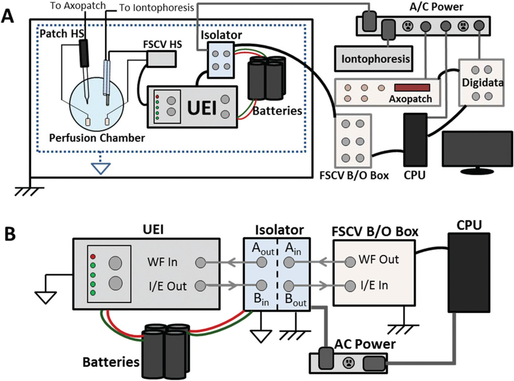
Fig. 1.
Instrumentation for combined recordings. (A) Block diagram of FSCV, patch clamp, and iontophoresis instruments. Patch clamp commands are generated at the CPU, amplified (Digidata, Axopatch), and applied at the patch headstage. All components are referenced to AC ground. Similarly, iontophoresis currents are AC ground-referenced. For FSCV, commands originate at the CPU referenced to AC ground. These are amplified (B/O box) and transduced (isolator) to a battery-referenced potential. The UEI, powered by the battery, receives the command and applies the waveform at the electrode. (B) Transduction of FSCV signals. The waveform command is sent from the CPU to the isolator (‘WF Out’ to ‘Ain’), and arrives at the UEI after transduction (‘Aout’ to ‘WF in’). FSCV current is transduced through the isolator (‘I/E out’ to ‘Bin’) and recorded by the CPU (‘Bout’ to ‘I/E in’).

