Abstract
3D printing of composite materials offers an opportunity to combine desired properties of composite materials with flexibility of additive manufacturing in geometric shape and complexity. In this paper, shear-induced alignment of aluminum oxide nanowires during stereolithography printing was utilized to fabricate a nanowire reinforced polymer composite. To align the fibers, a lateral oscillation mechanism was implemented and combined with wall pattern printing technique to generate shear flow in both vertical and horizontal directions. A series of specimens were fabricated for testing the composite material's tensile strength. The results showed that mechanical properties of the composite were improved by reinforcement of nanofibers through shear induced alignment. The improvement of tensile strength was approximately ~28% by aligning the nanowires at 5wt% (~1.5% volume fraction) loading of aluminum oxide nanowires.
Keywords: Additive manufacturing, 3D printing, Stereolithography, Fiber Reinforced Polymer, Nanocomposite, Fiber Orientation
INTRODUCTION
One dimensional (1D) nanoscale particulates (NPs) such as nanorods, nanofibers, and nanotubes have been widely used for medicine [1], electronics [2, 3], and photonic applications [4, 5]. NPs are combined with matrix in a controlled dimension and percentage to improve various properties, such as mechanical, electrical, and thermal properties, thus there is also growing interest in nanocomposites [6-11]. These improvements are directly related with the material, dimensions, and orientation distribution of fibers. Orientation distribution with respect to fiber length and concentration is one the most important factors that influences the ultimate strength of a fiber-reinforced composite structure. The influence of fiber length, orientation and distribution on tensile strength was studied by Fu and Lauke analytically [12, 13]. Analysis of Fu and Lauke showed that strength of the composites increases with increase in fiber length, interfacial adhesion strength and fiber orientation. Increase in fiber orientation was described by decrease in mean fiber angle relative to direction of the force. Along the alignment direction, not only strength of material increases but also thermal and electrical conductivity of material increases [14]. Therefore 1D NPs have become increasingly attractive for researcher. Different methods of aligning 1D nanostructures exist in literature[15], such as electric field induction [16, 17], magnetic field induction [14, 18], chemical surface modification[19], nanoimprint lithography[20], flow induced alignment[21].
3D printing is a manufacturing process of making complex solid objects from a digital file in forms of successive layers. Addition of fiber reinforcement into 3d printing material was demonstrated successfully to produce reinforced polymer composite (RPC) for Fused deposition modelling (FDM) [22, 23], Stereolithography (SLA) [24, 25], inkjet printing [26]. Flow induced alignment is easily achievable for FDM and inkjet printing. FDM and inkjet printing include a nozzle where material flows through. Shear generated within the nozzle provides partial alignment of short fibers in the direction of the extrusion [22, 23, 26]. On the other hand, alignment of short fibers during SLA 3d printing was demonstrated by magnetic and acoustic fields [24, 25]. However alignment by electric or magnetic fields limit the material of reinforcement because they require particles with specific electrical and magnetic properties. Acoustic field is a useful method to distribute and pattern particles towards pressure nodes or anti-nodes in the matrix medium [25]. Although acoustic field manipulates the particles to form distinctive long parallel strand of lines, the individual fibers have a degree of misalignment which increases with higher particle volume fractions [27].
In this paper, we demonstrated that shear induced alignment can be used instead of magnetic and acoustic alignment to have better distribution and orientation of fibers without material constraints. We developed a new method to use flow induced alignment during Digital Light Processing (DLP) based SLA 3D printing. Linear oscillatory actuation mechanism (LOAM) was combined with SLA device to generate Couette flow which was used for alignment. Aluminum oxide nanofibers (AONWs) were treated with silane coupling agent and were used as an additive to enhance interfacial bond between NPs and matrix material. Printed wall pattern was also accompanied with LOAM to provide additional alignment of the nanofibers. Our method of using shear induced alignment provides a simple and cheap method for alignment of 1D NPs during SLA 3D printing.
MATERIALS AND METHOD
Materials
Acrylate based photocurable polymer purchased from Madesolid to be used as a matrix for nanofiber reinforced polymer composite (NFRPC). The density and the viscosity of the resin were provided by supplier as 1.12 g/cm3 and 361 cP at 20°C. AONWs with 2-6 nm diameter and 200-400 nm length were purchased from Sigma-Aldrich to be used as the reinforcement of the composite. AONWs and photocurable polymer are two dissimilar materials and a coupling reaction is necessary to provide a chemical bond between them. In order to couple the matrix and nanowires, 3-(Trimethoxysilyl)propyl methacrylate (TMSPMA) purchased from Sigma-Aldrich and was used as a coupling agent.
Aluminum oxide is a widely used metal oxide of great importance in the industry due to its high strength, chemical stability, electrical and thermal insulation, and corrosion resistance. AONWs also attract attention in research field for some experimental and commercial composite application with high performance [28]. The addition of nanowires is intended to improve the mechanical, thermal, or chemical properties compared to the neat matrix. These enhancements are significantly affected by introduction of surface coupling for better interfacial adhesion. Aluminum oxide is cheaper than other alternative options and can be functionalized to improve interfacial interaction between aluminum oxide and polymer [7, 29].
To introduce coupling agent onto surface of AONWs, TMSPMA was dissolved in 95% ethanol – 5% water solution with acetic acid to lower pH to 4.5-5.5. The amount of silane, which was added to solution, was calculated according to Equation 1 [30].
| (1) |
where, X is the amount of silane, mnw is the amount of nanowires, Ass is specific surface area of nanowires, and ω is the specific wetting surface of silane. In this study, the specific wetting surface of silane was ω = 315 m2/g and the specific surface area of nanowires was Ass > 360 m2/g. As a result, the minimum necessary amount of silane to treat 1 g of nanowire powder was calculated as 1.14 g. AONWs was initially dehydrated at 60°C for 24 hours and was silanated in the solution by stirring for 5 minutes at room temperature. Then the mixture was separated by decanting the solution. The nanowires were rinsed twice with acetone and silane layer was postcured for 2 hours at 60°C [29]. Photocurable resin combined with untreated and treated nanowires in the ratios of 1, 2, 3, 4, and 5 wt% were used for the control and test specimens. Possible existing bubbles in the suspension were removed by vacuum degassing. Additionally ultrasonic cavitation was used for better dispersion of the nanowires into photocurable resin.
Design Setup
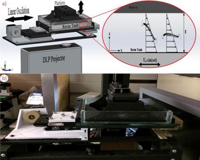
Figure 1 shows our designed DLP based SLA desktop 3D printer. A simple lateral harmonic motion mechanism was also incorporated to generate Couette flow. To manipulate the orientation of the nanofibers, we first fabricated patterns of micro channels specifically designed to align the fibers in the desired direction. Then we used linear harmonic oscillation to align the fibers. It was observed that nanowires with 2-6 nm diameter and 200-400 nm length were responding to alignment process. The designed 3D printer can manufacture complex structure with minimum feature size of 50 μm.
Figure 1.
DLP based SLA desktop 3D printer and incorporated linear harmonic oscillator mechanism. (a) 3D demonstration of the system consists of linear oscillation mechanism, platform, resin tank, and DLP projector. (b) Photo of 3D printer during linear oscillation process
DLP based SLA desktop 3D printer consists of a linear sliding mechanism oscillating with Uo sin(ωt), a resin tank with the dimensions of 140 × 190 × 36 mm3, DLP projector and a platform with the surface dimensions of 130 × 165 mm2. A linear slide is connected to a cam mechanism which is driven by a stepper motor. A schematic demonstration of oscillatory Couette flow generated by the system is shown in Figure 1a.
Fiber Alignment
Fiber motion and orientation in a simple shear flow has been studied extensively in literature [31-36]. Without a solid boundary, single fiber in the simple shear flow will tend to align in the shear direction with periodic rotations. Such periodic tumbling motion in simple shear flow was described by Jeffery's orbit [31] and was validated for diluted suspensions [32, 33]. The characteristics of fiber motion are affected by the existence of a solid boundary. When fibers are near a solid wall, they align better and faster than what Jeffery's equation predicts [34-36]. In addition, if aspect ratio of fibers increases, they cannot be considered as rigid rod. This creates a sudden decrease in the period of the motion. General behavior of a flexible fiber in a shear flow was demonstrated by Arlov, Forgacs & Mason as flexible spin, flexible spin superimposed on a spherical elliptical orbit, springy rotation, snake turn, and s-turn forms [35].
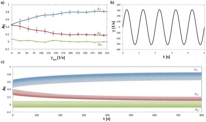
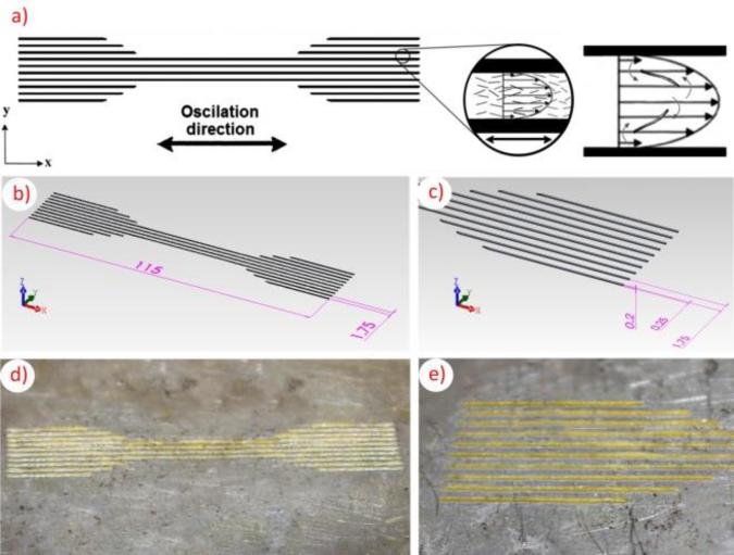
In a simple shear flow, channel width and thickness affect the alignment significantly. In wide channels, while fibers align in the flow direction near the walls, they orient perpendicular to the flow at the center of the channel [36, 37]. The region in the center of the channel is called core layer. the regions near the walls are called skin layers. If the channel is thin enough, the core layer will disappear and fibers will perfectly align in the flow direction. In similar studies for micro injection molding, skin-core morphology was still visible in the range of 300-500 μm [38-40]. As the thickness goes below 200 μm, it resulted with core-free morphology [40-42]. Thickness is not the only factor which effects fiber alignment. Without sufficient shear rate even the thicknesses down to 100 μm cannot provide core-free morphology [43, 44]. In our device, we set the thickness between platform and resin tank as 200 μm. We studied different velocity and frequency settings to find optimal shear rate and frequency values for sufficient alignment. The result of experimental study for influence of shear rate on fiber orientation tensor is shown in Figure 4a. Figure 4b illustrates time dependent shear rate profile at a maximum shear rate of (γmax) 314 s−1 and frequency (ω) of 1 Hz which used for ultimate strength tests. Additionally Figure 4c shows results for time dependent fiber orientation tensor at frequency of 0.05 Hz. We also proposed the use of printed wall patterns to manipulate the local flow of resin which is driven by oscillation. While the oscillation creates simple flow which provides alignment on x-y plane, the printed wall pattern provides additional alignment along channel direction. Wall pattern is designed parallel to the oscillation direction to align fibers in same direction as shown in Figure 2.
Figure 4.
Demonstration of shear rate profile and influence of maximum shear rate and frequency on fiber orientation tensor. (a) The influence of maximum shear rate γmax, on orientation tensor at frequency of f = 1Hz and 5wt% AONWs loading, (b) The time dependent- shear rate profile which was used in ultimate strength tests, (c) The time dependent fiber orientation distribution at γmax = 314s−1 and f = 0.05Hz with 5wt% AONWs loading
Figure 2.
Three dimensional and optical images of wall pattern for test specimen fabrication; the width of the walls is 250 μm, the distance between walls is 1.75 mm, and the height of the wall is 200 μm
Fabrication of Test Specimens and Mechanical Testing
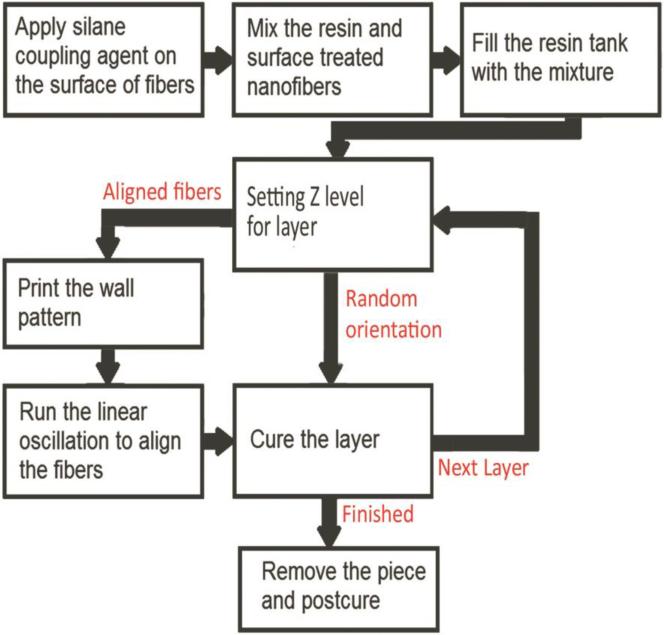
Figure 3 shows the diagram of the fabrication steps for test specimens. First, TMSPMA was applied on the surface of the AONWs as described in Section 2.1. Then, treated nanowires were mixed with photocurable resin with 1, 2, 3, 4, 5 wt% fraction ratios. Prepared suspensions were placed in resin tank to fabricate test specimens. The distance between platform and resin tank was set for layer thickness. Layer thickness was 200 μm for our test specimens. Wall pattern shown in Figure 2 was printed to guide the fibers in the oscillation direction for fabrication of the layers with aligned fibers. Lateral linear oscillator was turned on to align the fibers. Time-dependent maximum shear rate of 314 s−1 was generated by lateral oscillation mechanism for 1000 cycles (Figure 4). After that the resin was exposed to the projected image from DLP projector and was cured. The last three processes, consisting of wall pattern fabrication, alignment by oscillation, and finishing the layer by curing, were repeated for every layer. Following the removal of the specimens from platform, they were post-cured further and ready for mechanical testing. The fabrication steps for randomly oriented specimens do not include printing the wall pattern and linear oscillation which are only necessary to align the fibers.
Figure 3.
Flow chart of the fabrication process
Uniaxial tensile tests were performed at room temperature (20–25°C) with constant 1 mm/min displacement rate. Nominal strain rate was 0.1 mm/mm·min at start of the test. Each data was collected as average of 5 independent printed specimens. The shape and dimensions of specimens are illustrated in Figure 5. All specimens were printed with 0.2 mm layer thickness and total of 20 layers
Figure 5.
Geometry of the tensile test specimens; dimensions are in millimeters
RESULTS AND DISCUSSION
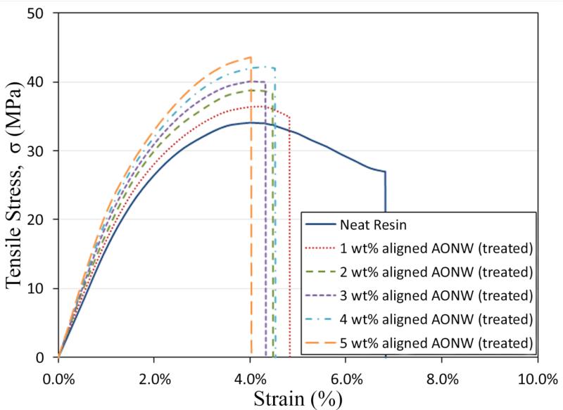
Tensile stresses-strain curves of nanocomposites are plotted out in Figure 6. This includes unreinforced photocurable resin for comparison and it shows that tensile strength of specimen increases with increasing nanofiber content.
Figure 6.
Tensile stress-strain curves of the surface treated aligned AONW reinforced nanocomposites.
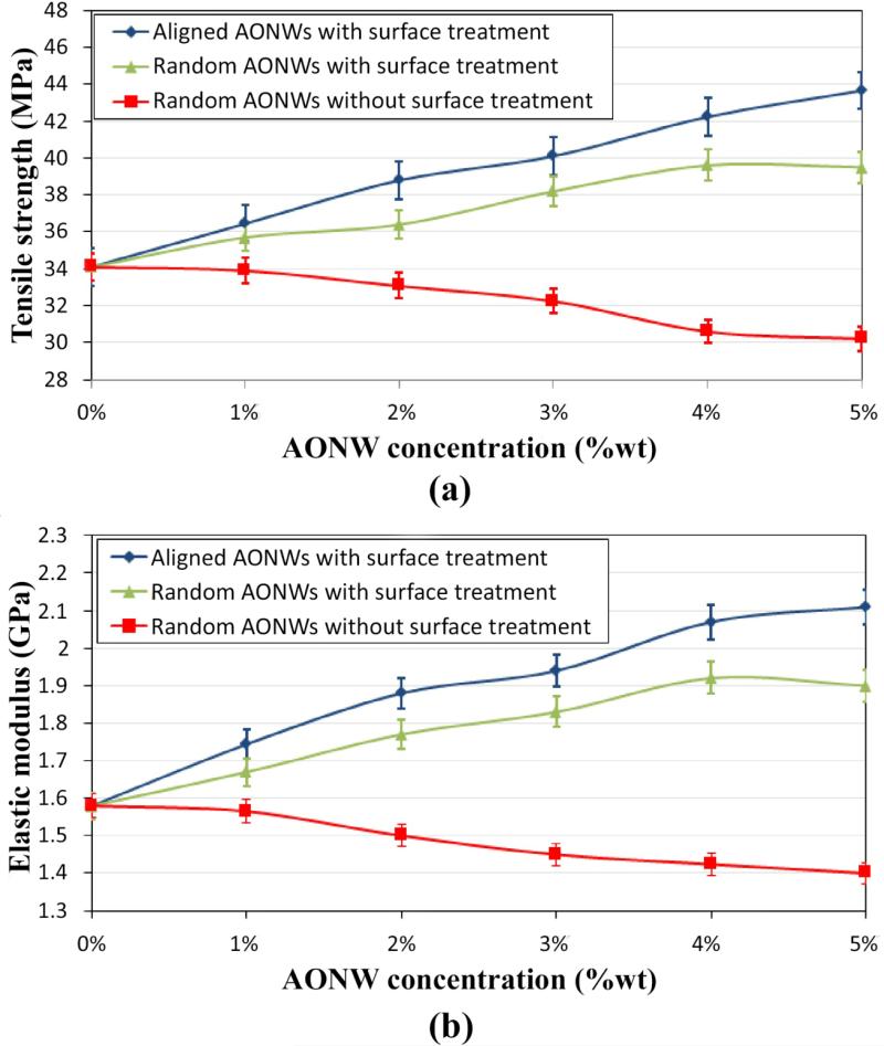
The tensile properties of the aligned and randomly orientated nanocomposites are plotted in Figure 7. Figure 7a shows that the addition of reinforcement gradually decreases the tensile strength without surface treatment as it was expected. Significantly larger surface areas of the nanowires compared to similar masses of larger scale particles causes greater aggregation of NPs. It was observed that the use of surface coupling agent improves interfacial interaction between AONWs and polymer matrix. Subsequently it enhances the tensile strength and elastic modulus when the reinforcement has higher stiffness than the matrix (as shown in Figure 7a). With the use of surface coupling agent, 5 wt% randomly orientated AONW reinforcement (1.5 % volume fraction) provides 15% improvements in tensile strength and 20% improvement in elastic modulus of the nanocomposite. The comparison between randomly orientated sample with 5wt% and the specimen with 5wt% align AONWs clearly shows the effect of orientation distribution on ultimate strength of NFRPC. The alignment of fibers provides additional 13% improvement to the elastic modulus and ultimate strength of NFRPC in the alignment direction (as shown in Figure 7a and b). This enhancement of ultimate strength with increase in fiber orientation is in line with general knowledge of composite materials. 5 wt% aligned AONWs in nanocomposite with surface treatment enhances tensile strength 28% and elastic modulus 34%.
Figure 7.
Tensile strength and elastic modulus of random and aligned AONW reinforced composites with different concentrations; (a) Tensile strength, (b) Elastic modulus.
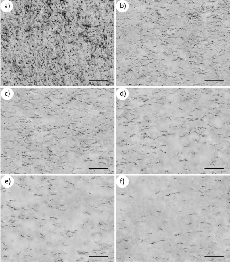
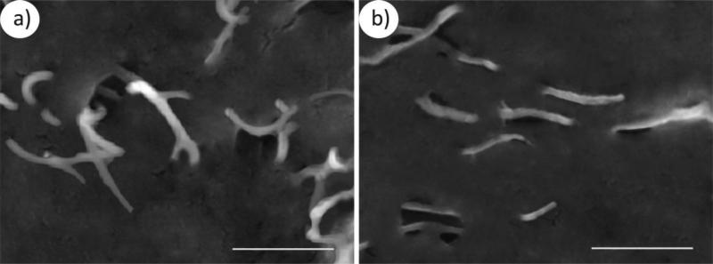
The dispersion and alignment of AONWs in the polymer matrix are illustrated in Figure 8 as transmission electron microscopy (TEM) and in Figure 9 as scanning electron microscopy (SEM) images. Figure 8a,b,c,d,e,f are TEM images which illustrates dispersion and alignment of the samples and they were also used for orientation distribution analysis. The AONWs were clearly shown to change from random orientation to be aligned along the shear direction. However, there was no visible difference in the fiber orientation distribution between aligned 1, 2, 3, 4, 5 wt% fraction ratio specimens. Analysis does not provide any evidence for influence of nanowires loading on the orientation distribution.
Figure 8.
TEM images of nanowire alignment and dispersion within printed components (Scale bars are 1 μm); (a)TEM image of randomly orientated AONWs, (b)TEM image of aligned AONWs with 5wt% reinforcement, (c) TEM image of aligned AONWs with 4wt% reinforcement, (d) TEM image of aligned AONWs with 3wt% reinforcement, (e) TEM image of aligned AONWs with 2wt% reinforcement, (f) TEM image of aligned AONWs with 1wt% reinforcement.
Figure 9.
SEM images of nanowire alignment within printed components (Scale bars are 50 nm); (a)SEM image of randomly orientated AONWs, (b) SEM image of aligned AONWs with 5wt% reinforcement.
CONCLUSIONS
Shear-induced fiber alignment technique was used to fabricate AONW reinforced polymer composite. DLP based stereolithography desktop 3D printer, incorporated with lateral linear oscillation mechanism, was designed and built to demonstrate the technique. Polymer nanocomposite specimens, containing 1–5wt% of AONWs, were prepared with silane surface coupling agent to enhance interfacial interaction between nanofibers and matrix. Oscillation mechanism combined with printed wall pattern was used to generate shear induced unidirectional alignment in test specimens. Tensile tests showed that Young's modulus and the tensile strength enhances with the increase in nanowire concentration and alignment of the nanowires. Only with 5wt% (1.5% by volume) nanofiber, 28% improvement in strength is achieved by the alignment of the nanowires. Further improvement can be expected to be achieved by increasing the volume fraction of the nanofibers. Alignment of the fibers can be achieved in any direction on x-y plane by changing the wall pattern.
Comparisons between different shear rates, frequencies, AONWs loading were performed and their influence on orientation distribution of AONWs and ultimate strength investigated. TEM images of Figure 8 show that AONWs were well dispersed in polymer matrix and suggested our shear approach aligned the AONWs in desired direction. Shear rates were illustrated to have significant influence in AONWs orientation (Figure 4a) while frequency and AONWs loading has almost no visible effect on orientation.
In summary, this novel research demonstrates a method for nanofiber alignment during rapid prototyping. This method has potential for production of tailored anisotropy in fiber reinforced nanocomposites. It might also be used in applications such as high strength, electronic, photonic, and flexible metamaterials.
ACKNOWLEDGMENTS
The authors acknowledge that this research was partially supported by National Science Foundation (NSF) grants CBET-1113040, DMS-1516236, CBET-1264808, and National Institutes of Health (NIH) grant EB015105.
REFERENCES
- 1.Chung W-J, Oh J-W, Kwak K, Lee BY, Meyer J, Wang E, Hexemer A, Lee S-W. Biomimetic self-templating supramolecular structures. Nature. 2011;478:364–8. doi: 10.1038/nature10513. [DOI] [PubMed] [Google Scholar]
- 2.Lee S, Shin S, Lee S, Seo J, Lee J, Son S, Cho HJ, Algadi H, Al-Sayari S, Kim DE. Ag nanowire reinforced highly stretchable conductive fibers for wearable electronics. Advanced Functional Materials. 2015;25:3114–21. [Google Scholar]
- 3.Zheng Z, Gan L, Zhai T. Electrospun nanowire arrays for electronics and optoelectronics. Science. 2016;59:201. [Google Scholar]
- 4.Duan X, Niu C, Sahi V, Chen J, Parce JW, Empedocles S, Goldman JL. High-performance thin-film transistors using semiconductor nanowires and nanoribbons. Nature. 2003;425:274–8. doi: 10.1038/nature01996. [DOI] [PubMed] [Google Scholar]
- 5.Yan R, Gargas D, Yang P. Nanowire photonics. Nature Photonics. 2009;3:569–76. [Google Scholar]
- 6.Xu GC, Wang J, Ji XL, Xiong JY, Li F. Effect of nano-silicon nitride on the mechanical and electric properties of polypropylene nanocomposite. Journal of Composite Materials. 2007;41:2213–23. [Google Scholar]
- 7.Guo Z, Pereira T, Choi O, Wang Y, Hahn HT. Surface functionalized alumina nanoparticle filled polymeric nanocomposites with enhanced mechanical properties. Journal of Materials Chemistry. 2006;16:2800–8. [Google Scholar]
- 8.Kirca M, To AC. Mechanics of CNT Network Materials. Advanced Computational Nanomechanics. 2015;29 [Google Scholar]
- 9.Yin J, Retsch M, Thomas EL, Boyce MC. Collective mechanical behavior of multilayer colloidal arrays of hollow nanoparticles. Langmuir. 2012;28:5580–8. doi: 10.1021/la300039v. [DOI] [PubMed] [Google Scholar]
- 10.Deng F, Ito M, Noguchi T, Wang L, Ueki H, Niihara K-i, Kim YA, Endo M, Zheng Q-S. Elucidation of the reinforcing mechanism in carbon nanotube/rubber nanocomposites. ACS nano. 2011;5:3858–66. doi: 10.1021/nn200201u. [DOI] [PubMed] [Google Scholar]
- 11.Xia Y, Yang P, Sun Y, Wu Y, Mayers B, Gates B, Yin Y, Kim F, Yan H. One-dimensional nanostructures: synthesis, characterization, and applications. Advanced materials. 2003;15:353–89. [Google Scholar]
- 12.Fu S-Y, Lauke B. Effects of fiber length and fiber orientation distributions on the tensile strength of short-fiber-reinforced polymers. Composites Science and Technology. 1996;56:1179–90. [Google Scholar]
- 13.Fu S-Y, Lauke B. The elastic modulus of misaligned short-fiber-reinforced polymers. Composites science and technology. 1998;58:389–400. [Google Scholar]
- 14.Hone J, Llaguno M, Nemes N, Johnson A, Fischer J, Walters D, Casavant M, Schmidt J, Smalley R. Electrical and thermal transport properties of magnetically aligned single wall carbon nanotube films. Applied physics letters. 2000;77:666–8. [Google Scholar]
- 15.Su B, Wu Y, Jiang L. The art of aligning one-dimensional (1D) nanostructures. Chemical Society Reviews. 2012;41:7832–56. doi: 10.1039/c2cs35187k. [DOI] [PubMed] [Google Scholar]
- 16.Sakar M, Balakumar S, Saravanan P, Jaisankar SN. Electric field induced formation of one-dimensional bismuth ferrite (BiFeO 3) nanostructures in electrospinning process. Materials & Design. 2016;94:487–95. [Google Scholar]
- 17.Liu Y, Chung J-H, Liu WK, Ruoff RS. Dielectrophoretic assembly of nanowires. The Journal of Physical Chemistry B. 2006;110:14098–106. doi: 10.1021/jp061367e. [DOI] [PubMed] [Google Scholar]
- 18.Jiang X, Feng J, Huang L, Wu Y, Su B, Yang W, Mai L, Jiang L. Bioinspired 1D Superparamagnetic Magnetite Arrays with Magnetic Field Perception. Advanced Materials. 2016 doi: 10.1002/adma.201601609. [DOI] [PubMed] [Google Scholar]
- 19.Kwak G, Seol M, Tak Y, Yong K. Superhydrophobic ZnO nanowire surface: chemical modification and effects of UV irradiation. The Journal of Physical Chemistry C. 2009;113:12085–9. [Google Scholar]
- 20.Rao SG, Huang L, Setyawan W, Hong S. Nanotube electronics: large-scale assembly of carbon nanotubes. Nature. 2003;425:36–7. doi: 10.1038/425036a. [DOI] [PubMed] [Google Scholar]
- 21.Li Y, Wu Y. Coassembly of graphene oxide and nanowires for large-area nanowire alignment. Journal of the American Chemical Society. 2009;131:5851–7. doi: 10.1021/ja9000882. [DOI] [PubMed] [Google Scholar]
- 22.Compton BG, Lewis JA. 3D-printing of lightweight cellular composites. Advanced Materials. 2014;26:5930–5. doi: 10.1002/adma.201401804. [DOI] [PubMed] [Google Scholar]
- 23.Zhong W, Li F, Zhang Z, Song L, Li Z. Short fiber reinforced composites for fused deposition modeling. Materials Science and Engineering: A. 2001;301:125–30. [Google Scholar]
- 24.Nakamoto T, Kojima S. Layered Thin Film Micro Parts Reinforced with Aligned Short Fibers in Laser Stereolithography by Applying Magnetic Field. Journal of Advanced Mechanical Design, Systems, and Manufacturing. 2012;6:849–58. [Google Scholar]
- 25.Llewellyn-Jones TM, Drinkwater BW, Trask RS. 3D printed components with ultrasonically arranged microscale structure. Smart Materials and Structures. 2016;25:02LT1. [Google Scholar]
- 26.Lee H, Seong B, Kim J, Jang Y, Byun D. Direct Alignment and Patterning of Silver Nanowires by Electrohydrodynamic Jet Printing. Small. 2014;10:3918–22. doi: 10.1002/smll.201400936. [DOI] [PubMed] [Google Scholar]
- 27.Scholz M-S, Drinkwater B, Trask R. Ultrasonic assembly of anisotropic short fibre reinforced composites. Ultrasonics. 2014;54:1015–9. doi: 10.1016/j.ultras.2013.12.001. [DOI] [PubMed] [Google Scholar]
- 28.Mallick PK. Fiber-reinforced composites: materials, manufacturing, and design. CRC press; 2007. [Google Scholar]
- 29.Noordin MR, Liew KY. Synthesis of alumina nanofibers and composites. INTECH Open Access Publisher; 2010. [Google Scholar]
- 30.APPLYING A SILANE COUPLING AGENT. Gelest Reference Library; [Google Scholar]
- 31.Jeffery GB. Proceedings of the Royal Society of London A: Mathematical, Physical and Engineering Sciences. The Royal Society; 1922. The motion of ellipsoidal particles immersed in a viscous fluid. pp. 161–79. [Google Scholar]
- 32.Mason S, Manley RSJ. Proceedings of the Royal Society of London A: Mathematical, Physical and Engineering Sciences. The Royal Society; 1956. Particle motions in sheared suspensions: orientations and interactions of rigid rods. pp. 117–31. [Google Scholar]
- 33.Joung C, Phan-Thien N, Fan X. Direct simulation of flexible fibers. Journal of non-newtonian fluid mechanics. 2001;99:1–36. [Google Scholar]
- 34.Moses KB, Advani SG, Reinhardt A. Investigation of fiber motion near solid boundaries in simple shear flow. Rheologica Acta. 2001;40:296–306. [Google Scholar]
- 35.Carlsson A. Near wall fibre orientation in flowing suspensions. Department of Mechanics: KTH Royal Institute of Technology; 2009. [Google Scholar]
- 36.Papthanasiou T, Guell DC. Flow-induced alignment in composite materials. Elsevier; 1997. [Google Scholar]
- 37.Oumer AN, Mamat O. A Review of Effects of Molding Methods, Mold Thickness and Other Processing Parameters on Fiber Orientation in Polymer Composites Asian. Journal of Scientific Research. 2013;6:401. [Google Scholar]
- 38.Ito H, Yagisawa Y, Saito T, Yasuhara T, Kikutani T, Yamagiwa Y. Fundamental study on structure development of thin-wall injection molded products. Theoretical and Applied Mechanics Japan. 2005;54:263–8. [Google Scholar]
- 39.Chu J, Hrymak A, Kamal M. ANTEC-CONFERENCE PROCEEDINGS. Citeseer; 2007. Microstructural characteristics of micro-injection molded thermoplastics. p. 1973. [Google Scholar]
- 40.Yang C, Yin X-H, Cheng G-M. Microinjection molding of microsystem components: new aspects in improving performance. Journal of Micromechanics and Microengineering. 2013;23:093001. [Google Scholar]
- 41.Giboz J, Copponnex T, Mélé P. Microinjection molding of thermoplastic polymers: morphological comparison with conventional injection molding. Journal of Micromechanics and Microengineering. 2009;19:025023. [Google Scholar]
- 42.Yang C. Flow-induced morphology evolution of uniformly miniaturized high-density polyethylene parts prepared by micro-injection molding. The International Journal of Advanced Manufacturing Technology. 2013;68:1745–55. [Google Scholar]
- 43.Lu Z, Zhang K. Morphology and mechanical properties of polypropylene micro-arrays by micro-injection molding. The International Journal of Advanced Manufacturing Technology. 2009;40:490–6. [Google Scholar]
- 44.Lu Z, Zhang K. Crystal distribution and molecule orientation of micro injection molded polypropylene microstructured parts. Polymer Engineering & Science. 2009;49:1661–5. [Google Scholar]


