Abstract
A 10-mm cavity length magnetooptically Q-switched Nd:GdVO4 laser was demonstrated using a single-crystalline ferrimagnetic rare-earth iron garnet film. To design the Q-switching system, the magnetic, optical, and magnetooptical properties of the garnet film were measured. The diode pumped solid-state laser cavity was constructed using a 190-μm-thick garnet film with 58% transmittance. The garnet film had maze-shaped magnetic domains, and the domain walls disappeared when a field of over 200 Oe was applied. Therefore, the polarization state of the transmitted light was modified by modulating the magnetization, and a Q-switched pulse output with a pulse width of 5 ns and peak power of 255 W was achieved in the 10-mm-long cavity. The physical limitation of the pulse width was discussed with the calculated results.
Rare-earth iron garnets (RIGs) are well known ferrimagnetic materials that are used in various communication applications such as optical isolators, microwave filters1, and bubble domain memories2. In general, RIGs have a garnet structure expressed as the general formula R3Fe5O12, where R indicates a rare-earth ion. Substituting elements in the R or iron site results in an interesting change in the magnetic and optical properties3,4,5, and variation in the substitution allows broad applications6,7 for RIGs. Despite the range of potential applications, there are few studies on magnetooptical (MO) Q-switches using RIGs. We have recently proposed the use of an RIG as a Q-switch because of its quick optical modulation speed, thin thickness to obtain sufficient changes of optical states, high transmissivity, and large MO effect in the near infrared region8.
For a Q-switch, Q-factor modulation of a laser cavity is required to generate high-power short laser pulses. In particular, diode-pumped solid-state micro lasers (DPSSMLs) attract much interest because they are compact (on the order of centimetres) and demonstrate high stability and efficiency9,10,11. To obtain giant pulse power and small timing jitter with the integrated DPSSML, active Q-switches based on electro-optical12,13 and acousto-optical effects14 are more suitable than passive Q-switches such as saturable absorbers. However, active Q-switches are difficult to miniaturize, and the obtained pulse width and peak power are limited. So far, the cavity length of active Q-switches has not been less than 10 mm.
To solve this issue, MO materials could be strong candidates for active Q-switches in DPSSMLs because of their ultrafast response time15,16 and their widely studied lamination techniques17,18. In 1995, Zhou et al. demonstrated an MO Q-switched laser with a paramagnetic material that showed a Q-switched laser pulse with a full width at half maximum (FWHM) of 100 ns19; however, there has been no significant progresses since this report. We recently showed the first MO Q-switched laser using RIG8, but its cavity length was not any shorter than other active Q-switches even though its thickness was less than 1 mm. Moreover, the detailed switching mechanism was not revealed, so the physical limitations could not be discussed.
In this study, we report an MO Q-switch using a short cavity that cannot be realized by other active Q-switches. This MO Q-switch is based on the motion of magnetic micro-domains (MMDs) in a ferrimagnetic garnet film. A single-crystalline RIG film sandwiched by two coils was installed in a diode end-pumped Nd:GdVO4 laser cavity, and Q-switching operation was demonstrated using the pulsed magnetic field.
Results and Discussion
Magnetooptical film
The 190-μm-thick single crystalline RIG film used as the MO Q-switch was fabricated on a 560-μm-thick Gd3Ga5O12 (GGG) substrate via liquid phase epitaxy. Both sides were polished to avoid light scattering. The magnetic, optical, and MO properties of the RIG were measured to design a pulse-field generator for Q-switching. A vibrating sample magnetometer (TM-VSM 261483-HGC, Tamakawa) and a spectrophotometer (UV-3150, Shimadzu) were used to study the magnetic and optical properties, respectively. Measurement of the Faraday rotation (FR) of the RIG was conducted using the rotating analyser method. For investigating the FR and obtaining MO images, a power meter (918D-IR-OD3, Newport) and a charge-coupled device (CCD) camera (QICAM Fast 1394, QImaging) were used as detectors, respectively. The entire measurement was conducted at room temperature.
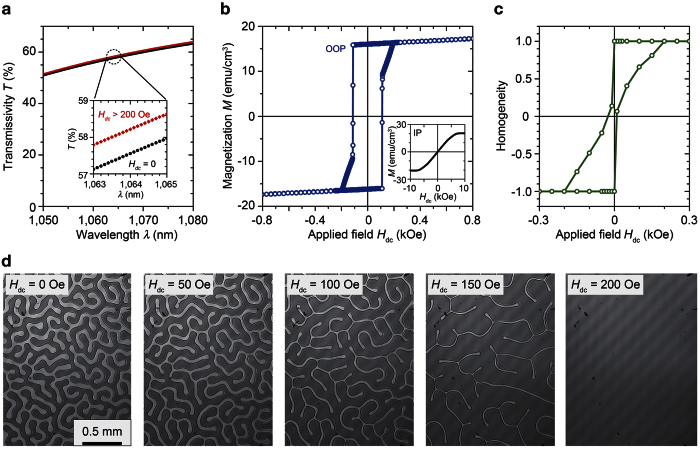
Figure 1a shows the transmittance of the RIG for applied magnetic fields of 0 Oe and 200 Oe. The applied field was perpendicular to the film surface. At the wavelength of 1,064 nm, which is the fluorescent wavelength of Nd:GdVO4, the transmittances of the RIG measured by the spectrophotometer with applied magnetic fields of 0 Oe and 200 Oe were 57.6% and 58.2%, respectively. The refractive index nMO and extinction coefficient κMO obtained by fitting software (SCOUT) based on the Fresnel equation were 2.23 and 1.03 × 10⁻⁴ (~ −53 dB/cm), respectively. Figure 1b shows the measured magnetic hysteresis loop. The easy axis was out-of-plane due to the crystalline anisotropy of film. The magnetization was saturated out-of-plane by an external magnetic field of over ~200 Oe, and the FR at the wavelength of 1,064 nm was ~47°. Figure 1c shows the homogeneity of the polarization state of the transmitted light obtained with the polarization microscope images shown in Fig. 1d. Maze-like magnetic domains with an average width of ~50 μm were observed in this garnet film without external magnetic field. These maze-like magnetic domains generated diffraction, showing a transmission difference of 0.6%.
Figure 1. Properties of the single crystalline garnet film.
(a) Transmittance spectrum of the magnetooptical garnet with/without the applied magnetic field. An enlarged plot in the vicinity of the wavelength of λ = 1,064 nm is shown in the inset. (b) Magnetic hysteresis loop of the garnet when the field was applied in the out-of-plane (OOP) direction. The in-plane (IP) magnetization loop is shown in the inset. (c) Homogeneity of the polarization plane state of the transmitted light through the garnet. (d) Polarization microscope images with various applied magnetic fields Hdc.
Laser set up
The constructed laser cavity is shown in the inset of Fig. 2. The aspects of the gadolinium vanadate crystal were 3 × 3 × 4 mm3 (a-cut and Nd 0.5 at.% doped), and the side faces were contacted with a copper heat sink, which was controlled with a Peltier module to keep the lasing material at 20 °C. The heat sink and the 300-mm curvature radius concave mirror (output coupler, OC) with a reflectance R of 90% at the wavelength of 1,064 nm were placed with the distance of L. The entire set up was fixed with a metal jig (Thorlabs). The OC can move along the rods to change the cavity length from 10 to 130 mm. This length was fixed in the Q-factor control experiment using a dc magnetic field. Pumping light at a wavelength of 808 nm was provided by a fibre-coupled continuous wave (CW) laser diode (LIMO32-F400-DL808, LIMO) and was focused on the centre of the Nd:GdVO4 crystal using a lens set. The lasing material was coated with dielectric mirrors: high reflectance (HR) of 99.8% at the wavelength of 1,064 nm and high transmittance (HT) of 98% at the wavelength of 808 nm on the input side. On the opposite surface of the Nd:GdVO4 crystal, the coating had HT of 98% at the wavelength of 1,064 nm and HR of 99.8% at the wavelength of 808 nm. The RIG was placed at 6 mm from the input surface of NdGdVO4. Figure 2 shows the beam diameter in the cavity estimated using a ray-trace program (Paraxia-Plus, SCIOPT) based on the physical constants of the used materials (see Methods). The spot diameter at the surface of the lasing material was 0.45 mm. On the garnet film, the spot diameter was changed as shown in the right bottom inset of Fig. 2; thus, the light transmitted through at least three magnetic domains when there was no applied field.
Figure 2. Beam diameter in the cavity with respect to the cavity length.
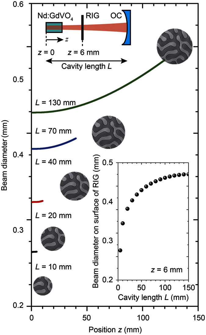
Lasing material Nd:GdVO4, RIG, and OC were placed in alignment as shown in the schematic on the upper left. The RIG was placed 6 mm from the Nd:GdVO4 surface (z = 6). The beam spot sizes at the surface of RIG with various cavity lengths are expressed by the circular images of MMDs, and the diameter is plotted in the bottom right inset.
Figure 3 shows the measured laser output versus pump power of the used laser cavity with and without the RIG. No magnetic field was applied. The reflectance R of 90% showed the slope efficiency ηs of 64.1%, and the threshold power was 0.29 W. The prepared RIG was inserted into this cavity; as a result, ηs was degraded to 4.6 × 10⁻⁴%, and the threshold power was 1.29 W. The increased loss and degraded slope efficiency were due to the absorption of the garnet film and its surface reflection. These properties can be decreased by improving the composition and optimization of the anti-reflection coating.
Figure 3. Output properties of the laser cavity with/without MO film.
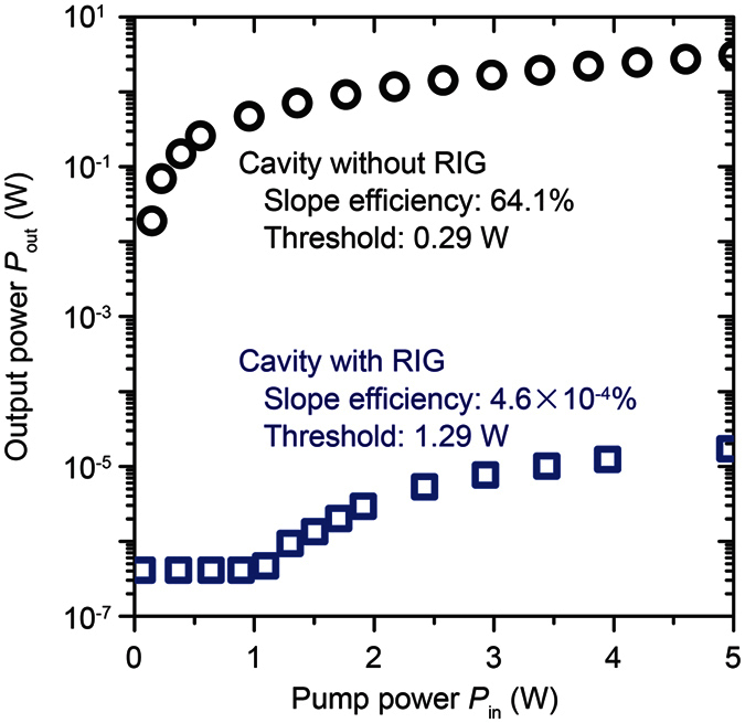
Output power of the laser under CW operation with respect to the pump power. Circles and squares show the output characteristics of the cavity with and without the RIG, respectively.
Magnetic-domain-controlled Q-factor
To understand the effect of domain motion, the Q-factor was changed by the dc field by changing the position of the ring-shaped samarium cobalt permanent magnet. The internal diameter of the magnet was 7 mm, the outer diameter was 12 mm, and the thickness was 3.5 mm. The generated magnetic field was uniform on the garnet in the beam exposure area. A sufficient magnetic field for saturating the used magnetic garnet was obtained by moving the permanent magnet. The laser properties and those for the laser containing magnetic garnet were measured.
The output power was changed as a function of the dc magnetic field via the MMD motion of the garnet film. The power was increased by two orders of magnitude by applying a saturation magnetic field of ~200 Oe. Moreover, the Q-factor measured by the spectral analyser of the output was increased from 887 to 986. This increase is due to the banishment of the magnetic domains. When the FR is 0°, the polarization plane of the light, which passed through the different domains, would be rotated to a different direction. This rotation direction depends on the magnetization direction of the passed magnetic domains. These lights are spatially overlapped and mixed in the cavity. The lack of uniformity of the polarization states of the transmitted light could cause a decrease in the Q-value of the cavity. In contrast, when the FR is over 47°, the polarization state of the transmitted light is spatially uniform; thus, the output power was drastically increased, indicating controllability of the laser power by the garnet film.
Magnetooptical Q-switching
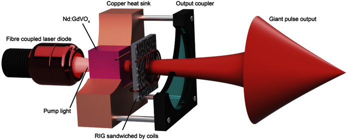
Subsequently, MO Q-switching with a pulsed field was conducted in the cavity. The RIG sandwiched by coils enabled the generation of a sufficient magnetic field to saturate the magnetization of the garnet film. The diameter of the coil (~5.3 mm) was sufficiently large to allow the beam to pass through the coil. The number of turns in the coil (3 turns) was minimized to decrease the inductance that would shorten the width of the electrical pulse. This MO Q-switch set was inserted in the cavity. Figure 4 shows a schematic of the used laser cavity with the MO Q-switch setup sandwiched by coils; part of the heat sink and the OC are cut away for better visualization of the setup. The distance between the lasing material and the OC was changed, and the peak power and pulse width of the MO Q-switch were measured.
Figure 4. Schematic of the laser-diode end-pumped Nd:GdVO4 laser cavity containing the RIG sandwiched by a pair of 5.3-mm diameter coils.
The lasing material was fixed in the copper heat sink. The heat sink and the OC formed a cage-shaped system with rods, and the cavity length can be changed within 10–130 mm.
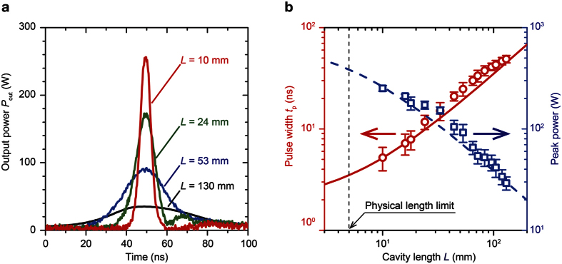
The pulsed field for Q-switching was generated by a pulsed current with an amplitude of 56 A and width of 2.5 μs. The obtained Q-switched pulse from the 130-mm-long cavity had a peak power of 30 W and FWHM of 45 ns. This was comparable with our previous report8. The cavity length was changed from 130 mm to 10 mm. When the cavity is shortened, reduction of the pulse width and an increase of the peak power was achieved, as shown in Fig. 5a. Figure 5b shows the change of the output pulse width and peak power when the cavity length was varied. The pulse width proportionally decreased with the cavity length, and the peak power was inversely proportional to the decreasing cavity length. The shortest pulse width tp was 5 ns, and the largest peak power was 255 W; thus, 1.3 μJ/pulse. The repetition rate was 100 Hz. The peak power of 255 W was 3.4 × 10⁴ times larger than that under CW operation.
Figure 5. MO Q-switched pulse output characteristics.
(a) Output pulse shapes when the cavity length was changed within 10–130 mm. (b) Pulse width and peak power as a function of the cavity length. The pulse width (red circles) was decreased, and the peak power (blue squares) was increased as the cavity was shortened. The error bars show the standard deviation of ten duplicate measurements. The calculated value of the pulse width (solid curve line) and peak power (dashed curve line) with the changing cavity length is also plotted. The vertical dashed line indicates the physical length limit of the cavity because of the total thickness of the used Nd:GdVO4 and RIG (L = 4.75 mm).
Discussion with theoretical analysis
The measured pulse width tp can be written as20,21
 |
where r is the inversion ratio, η is the energy extraction efficiency, and τc is the round-trip time in the cavity. Here, r and η can be described as r = Ni/Nth and η = (Ni − Nf)/Ni, respectively, where Ni is the initial population inversion, Nth is the threshold population inversion, and Nf is the final population inversion. Moreover, Ni, Nth, Nf, and τc can be described by Ni = δmax/(2σL), Nth = δmin/(2σL), Nf = Ni − Nth·ln(Ni/Nf), and τc = 2 L/(cδmin), respectively, where δmax (Q-switch is “OFF”) and δmin (Q-switch is “ON”) are, respectively, the maximum and minimum cavity losses, σ is the stimulated-emission cross-section of Nd:GdVO4 ( = 7.6 × 10⁻²³ m2), and c is the velocity of light ( = 3.0 × 10⁸ m/s). The minimum cavity loss δmin can be derived with the equation δmin = −ln(R) − 2ln(Ton), where R is reflectance of OC ( = 0.90) and Ton is the transmittance of RIG when a magnetic field of 200 Oe was applied (Ton = 0.582); thus, δmin = 1.188. The maximum cavity loss δmax was derived analytically with the measured tp shown in Fig. 5b. The average δmax within L = 10–130 mm was 1.258. These derived physical constants can be used to estimate the pulse width tp as a function of the inversion ratio r. In Fig. 6, the circle shows the shortest pulse width estimated when the cavity length is at its physical length limit (L = 4.75 mm). As the solid line shows, to improve this MO Q-switched laser, the inversion ratio r needs to be increased. Hence, an increase of δmax should contribute to the improvement of the MO Q-switched laser.
Figure 6. Pulse width tp estimation based on the rate equation of the Q-switched laser including RIG.
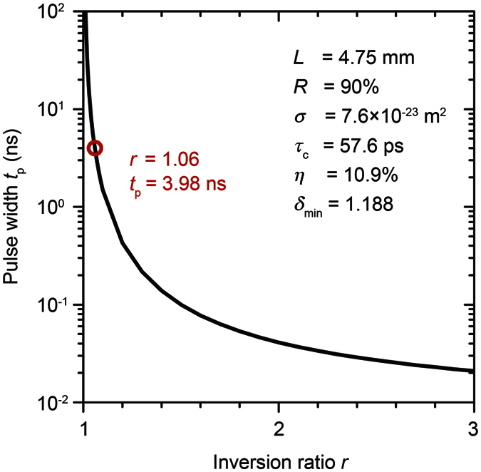
The red circle indicates the value of the inversion ratio and pulse width at the physical cavity length limit (L = 4.75 mm). The curved line plots the calculated dependence on various inversion ratios r using the cavity parameters shown in the inset. An increase of r can improve the pulse width.
Conclusion
We have reported that MMDs in a single-crystalline rare-earth-substituted iron garnet film caused Q-factor modulation in a laser cavity. The demonstrated active MO Q-switched laser with 10-mm cavity length provided a maximum peak power of 255 W with FWHM of 5 ns at a repetition rate of 100 Hz using a 190-μm-thick RIG film. This is the largest power and shortest pulse width obtained by MO Q-switches. In addition, the thickness of the Q-switch is extremely small in comparison with other reported active and passive Q-switches, which allowed us to construct the shortest active Q-switched laser system to our knowledge. Because the RIG could be epitaxially grown on lasing materials, we find the Q-switch system to be very promising for achieving actively Q-switched DPSSMLs, which have an even shorter cavity and a higher power output. Such MMDs can be controlled actively22 and quickly23, hence MO Q-switched laser can show novel functionalities in the near future.
Methods
Optical constants used in beam diameter characterizations
The used physical constants for the beam diameter calculation discussed with Fig. 2 are shown. The refractive indices of Nd:GdVO4, the GGG substrate, and the RIG film were 2.19, 1.94, and 2.23, respectively, and the thicknesses were 4 mm, 0.56 mm, and 0.19 mm, respectively. The curvature radius of the concave mirror (OC) was 300 mm.
Additional Information
How to cite this article: Morimoto, R. et al. Magnetic domains driving a Q-switched laser. Sci. Rep. 6, 38679; doi: 10.1038/srep38679 (2016).
Publisher's note: Springer Nature remains neutral with regard to jurisdictional claims in published maps and institutional affiliations.
Acknowledgments
This research acknowledges support from the Japan Society for the Promotion of Science (JSPS) KAKENHI No. 26706009, No. 26220902; and Ministry of Internal Affairs and Communications (MIC) SCOPE No. 0159-0117. We also thank Dr. Ryosuke Isogai, Mr. Naoki Kanazawa, Mr. Takuya Yoshimoto, Mr. Kazuki Nakamura, Dr. Hideki Ishizuki, and Dr. Yoichi Sato for useful discussions and experimental support.
Footnotes
The authors declare no competing financial interests.
Author Contributions R.M. and T.G. conducted the experiments and analysed the results. T.T. showed the method of the theoretical analysis. J.P. and M.M. designed and fabricated magnetic field generators. H.T., Y.N., P.L., H.U., and M.I. conducted the characterizations of the magnetic and magnetooptical responses of the fabricated samples.
References
- Gurevich A. G. & Melkov G. A. Magnetization oscillations and waves. (CRC Press, 1996). [Google Scholar]
- Sugita Y. In Physics and engineering applications of magnetism (eds Ishikawa Y. & Miura N.) 231–259 (Springer Berlin Heidelberg, 1991). [Google Scholar]
- Dionne G. F. Magnetic oxides. (Springer Berlin Heidelberg, 2009). [Google Scholar]
- Inoue M., Levy M. & Baryshev A. V. Magnetophotonics from theory to applications. (Springer Berlin Heidelberg, 2014). [Google Scholar]
- Sugano S. & Kojima N. Magneto-optics. (Springer Berlin Heidelberg, 2000). [Google Scholar]
- Stadler B. J. H. & Mizumoto T. Integrated magneto-optical materials and isolators: a review. IEEE Photon. J. 6, 1–15 (2014). [Google Scholar]
- Stanciu C. D. et al. All-optical magnetic recording with circularly polarized light. Phys. Rev. Lett. 99, 047601 (2007). [DOI] [PubMed] [Google Scholar]
- Goto T. et al. Magneto-optical Q-switching using magnetic garnet film with micromagnetic domains. Opt. Express 24, 17635–17643 (2016). [DOI] [PubMed] [Google Scholar]
- Byer R. L. Diode laser-pumped solid-state lasers. Science 239, 742–747 (1988). [DOI] [PubMed] [Google Scholar]
- Tsunekane M. et al. High peak power, passively Q-switched microlaser for ignition of engines. IEEE J. Quantum Elec. 46, 277–284 (2010). [Google Scholar]
- Sakai H., Kan H. & Taira T. >1 MW peak power single-mode high-brightness passively Q-switched Nd3+:YAG microchip laser. Opt. Express 16, 19891–19899 (2008). [DOI] [PubMed] [Google Scholar]
- Yu Z., Malmström M., Tarasenko O., Margulis W. & Laurell F. Actively Q-switched all-fiber laser with an electrically controlled microstructured fiber. Opt. Express 18, 11052–11057 (2010). [DOI] [PubMed] [Google Scholar]
- Velsko S. P., Ebbers C. A., Comaskey B., Albrecht G. F. & Mitchell S. C. 100 W average power at 0.53 μm by external frequency conversion of an electro-optically Q-switched diode-pumped power oscillator. Appl. Phys. Lett. 64, 3086–3088 (1994). [Google Scholar]
- Yu X. et al. Comparison of electro-optical and acousto-optical Q-switched, high repetition rate Nd:GdVO4 laser. Laser Physics 21, 442–445 (2011). [Google Scholar]
- Kimel A. V., Kirilyuk A. & Rasing T. Femtosecond opto-magnetism: ultrafast laser manipulation of magnetic materials. Laser & Photonics Reviews 1, 275–287 (2007). [Google Scholar]
- Pritchard J. W., Mina M. & Weber R. J. Improved switching for magneto-optic fiber-based technologies. IEEE Trans. Magn. 48, 3772–3775 (2012). [Google Scholar]
- Grishin A. M., Khartsev S. I. & Kawasaki H. 980 nm Bi3Fe5O12/Sm3Ga5O12 magneto-optical photonic crystal. Appl. Phys. Lett. 90, 191113–191113 (2007). [Google Scholar]
- Goto T. et al. Optical Tamm states in one-dimensional magnetophotonic structures. Phys. Rev. Lett. 101, 113902 (2008). [DOI] [PubMed] [Google Scholar]
- Zhou F. Z. et al. Compact, magneto-optic Q-switched, neodymium-dopedbismuth germinate crystal (Nd:BGO) laser pumped by a laser diode. Appl. Opt. 34, 4266–4268 (1995). [DOI] [PubMed] [Google Scholar]
- Siegman A. E. Lasers. (University Science Books, 1986). [Google Scholar]
- Pavel N., Saikawa J., Kurimura S. & Taira T. High average power diode end-pumped composite Nd:YAG laser passively Q-switched by Cr4+:YAG saturable absorber. Jpn. J. Appl. Phys. 40, 1253–1259 (2001). [Google Scholar]
- Rodionova V. et al. The defects influence on domain wall propagation in bistable glass-coated microwires. Physica B: Condensed Matter 407, 1446–1449 (2012). [Google Scholar]
- Ono T. et al. Propagation of a magnetic domain wall in a submicrometer magnetic wire. Science 284, 468–470 (1999). [DOI] [PubMed] [Google Scholar]


