Abstract
Purpose
The aim of this study was to assess the feasibility and advantages of a patient-specific breast bolus made using a 3D printer technique.
Methods
We used the anthropomorphic female phantom with breast attachments, which volumes are 200, 300, 400, 500 and 650 cc. We simulated the treatment for a right breast patient using parallel opposed tangential fields. Treatment plans were used to investigate the effect of unwanted air gaps under bolus on the dose distribution of the whole breast. The commercial Super-Flex bolus and 3D-printed polylactic acid (PLA) bolus were applied to investigate the skin dose of the breast with the MOSFET measurement. Two boluses of 3 and 5 mm thicknesses were selected.
Results
There was a good agreement between the dose distribution for a virtual bolus generated by the TPS and PLA bolus. The difference in dose distribution between the virtual bolus and Super-Flex bolus was significant within the bolus and breast due to unwanted air gaps. The average differences between calculated and measured doses in a 200 and 300 cc with PLA bolus were not significant, which were -0.7% and -0.6% for 3mm, and -1.1% and -1.1% for 5 mm, respectively. With the Super-Flex bolus, however, significant dose differences were observed (-5.1% and -3.2% for 3mm, and -6.3% and -4.2% for 5 mm).
Conclusion
The 3D-printed solid bolus can reduce the uncertainty of the daily setup and help to overcome the dose discrepancy by unwanted air gaps in the breast cancer radiation therapy.
Introduction
High energy photon beams for radiation therapy exhibit penetration, beam uniformity, and skin-sparing properties [1, 2]. This skin sparing near the surface inside a patient is caused by a dose build-up effect of megavoltage photon beam. The absorbed dose increases within a certain depth beyond the surface until they reach a maximum before megavoltage photon beam reaches electron equilibrium [3]. The ability to spare the skin is very useful for many different types of cancer, however, there is a problem with the treatment of superficial lesions near the skin surface. Thus, a build-up material (bolus) is placed in direct contact with the patient’s skin surface in order to increase the superficial dose and improve dose uniformity by compensating for missing tissue [4–6]. Normal organs including lung and heart could be protected because bolus brings isodose lines toward the surface and it was demonstrated that the use of bolus in the postmastectomy radiotherapy reduced the normal tissue complication probabilities (NTCPs) of the ipsilateral lung [7]. There are several bolus products currently available which are soft and rubbery tissue equivalent materials [8]. In case of the irregular surface region of a patient, unwanted air gaps under bolus might occur between the bolus and patient skin due to the malleability of bolus material.
Bustson et al. reported effects on skin dose from air gaps under bolus in the circumstances of breast cancer treatment [9]. That study was performed by different air gaps and oblique incident beams in a flat solid water phantom. Results of the larger air gap showed that the larger reduction of skin dose. The use of a solid bolus placed directly on the patient’s skin has been designed to deliver the desired dose to surface [10]. With manufacturing a solid bolus, several studies have shown the clinical efficacy for head and neck, post mastectomy irradiations, and paraspinal muscle treatment [11–15]. Using 3D printer techniques for radiation therapy has been gaining interest and the 3D printer can create a solid bolus without air gaps ideally.
The aim of this study was to assess the feasibility and advantages of a solid breast bolus made using a 3D printer technique. The bolus substance must be odorless, non-sticky, and harmless to the skin. In this study, thus, the polylactic acid (PLA) was adopted as a bolus material [16, 17]. We printed a patient-specific breast bolus for an anthropomorphic phantom and simulated a real patient treatment. The effects of different breast sizes and bolus thicknesses on the dose distribution were investigated between the commercial bolus and 3D-printed solid bolus.
Materials and Methods
Treatment simulation and planning
We used the anthropomorphic phantom (Model 702 Adult ATOM Female; CIRS Inc., Norfolk, VA) with breast attachments for our subject of study. This female phantom with breast attachments of various volumes (200, 300, 400, 500 and 650 cc) underwent the computed tomography (CT) scans with the Brilliance CT Big BoreTM (Philips, Amsterdam, Netherlands). These CT sets with no bolus material (CTno) were used to create the virtual bolus structure in the treatment planning system (TPS) and to design the 3D printing bolus. Furthermore, the female phantom, which the commercial bolus (Super-Flex bolus, Action Product Inc., Hagerstown, MD) was placed directly on the breast attachment, underwent other CT scans (CTbolus) in order to investigate the effect of unwanted air gaps near the breast surface and nipple. Two boluses of 3 and 5 mm thicknesses were selected for this study.
Conventional radiotherapy treatment of breast cancer used parallel opposed tangential fields as a primary plan to encompass the breast and then one electron beam were used for boost plan [18]. We simulated the treatment for a right breast patient. The primary plans were analyzed using 10 MV photon beams due to large breast volume for this study. The different dynamic wedge filters for different breast attachments were used to increase the dose in the ventral part of the breast while decreasing the dose in the dorsal part. Treatment plans were generated for all breast attachments with different bolus types. The plan_VB as an original plan was consisted of CTno sets and virtual bolus structures of water equivalent. The prescription dose to for a whole breast was 50.4 Gy in 28 fractions. Then, the plan_PLA was generated in CTno sets with virtual PLA bolus structures. The plan_bolus was generated in CTbolus sets including the Super-Flex bolus. The planning parameters of the plan_VB were applied to Plan_PLA and Plan_bolus, respectively. Dose distributions for all plans were calculated in EclipseTM (version A10, Varian Medical Systems, Palo Alto, CA) using the analytical anisotropic algorithm (AAA) with a calculation grid size of 2.5 mm.
3D breast bolus design and printing
A patient-specific breast bolus was manufactured using a 3D printer with a clear-PLA material. The design of the breast bolus for 3D printing was based on a CT image. The TPS imported the CT image sets without bolus materials. The boluses of 3 and 5 mm thicknesses were generated as a structure for each CT image set of different breast attachments and the shapes of these boluses were optimized to cover a whole breast without air gaps in the TPS. The bolus material generated in the TPS was set as water-equivalent. We used the clear-PLA material for the plastic material, however, its physical properties were not identical to those of water. The physical properties for the material are listed in Table 1. Thus, the water-equivalent depth of PLA was simply calculated with the ratio of water and PLA physical densities. The bolus thicknesses of 3 and 5 mm for the clear-PLA were reduced to 2.50 and 4.12 mm with 0.83 of the depth-scaling factor, respectively. A Hounsfield unit (HU) of clear-PLA also was set as 274 HU that was derived from an electron density ratio of 1.14 and mass density ratio of 1.2 compared to water.
Table 1. Physical properties of the clear-PLA and 3D printer settings.
| Print Setting | First Layer Setting | Physical Property of Clear-PLA | |||
|---|---|---|---|---|---|
| Bed Temperature | 65°C | Bed Temperature | 65°C | Chemical Formula | C3H4O2 |
| Extruder Temperature | 240°C | Extruder Temperature | 240°C | Physical Density | 1.2 g/cm3 |
| Extrusion Width | 0.44 mm | Extrusion Width | 0.57 mm | Electron Density ratio compared to water | 1.14 |
| Layer Height | 0.2 mm | Layer Height | 0.1 mm | Effective Z | 4.22 |
| Layer Speed(Default Printing Speed) | 50 mm/s | Layer Speed | 15 mm/s | ||
| Fill Density | 1 g/cm3 | ||||
| Fill Pattern | Rectilinear | ||||
| Fill Angle | 45° | ||||
| Perimeter Speed | 3.33 mm/s | ||||
| Perimeter Extrusion Width(Z axis Movement Speed) | 0.44 mm | ||||
| Nozzle Diameter | 0.4 mm | ||||
| Filament Diameter | 1.75 mm | ||||
| Extrusion Multiplier | 1 | ||||
| Z Offset | -1 mm | ||||
Abbreviations: PLA, poly lactic acid
All bolus structures of 10 (two boluses for one breast attachment) were exported to 3DSlicer (www.slicer.org), which is the open source software that converts a structure file to the standard tessellation language (STL) file. The converted STL file was interpreted by the 3D printing software Simplify3D® (www.simplify3d.com) and was sent to our 3D printer (MEISTER, 3D BOX Inc., Incheon, Korea). This 3D printer provides the Fused Deposition Modeling (FDM) technology. The optimized print settings for manufacturing the clear-PLA breast bolus are on the Table 1.
Evaluation of treatment plans
Treatment plans were generated to investigate the effect of unwanted air gaps between bolus and patient skin on the dose distribution of the whole breast. The planned dose difference was calculated for Plan_PLA and Plan_bolus compared to Plan_VB, respectively. The VeriSoftTM 3.1 (PTW, Freiburg, Germany) selected the center of the whole breast in the sagittal plane to calculate the dose difference without suppressing doses.
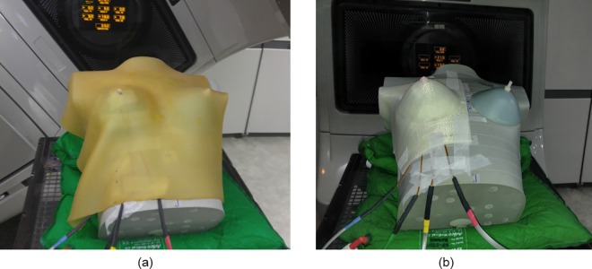
The MOSFET dosimeter (Best Medical Canada, Ottawa, ON, Canada) was used to measure skin doses of breast. The used MOSFET dosimeters were calibrated and the performance characteristics had been verified in the author’s previous study [19]. Both of Plan_VB and Plan_PLA were applied to measure skin dose, shown in Fig 1. For Plan_VB, the Super-Flex bolus was used to simulate the treatment condition. The same measurement points located on both sides of the nipple and breast were used for both of Plan_VB and Plan_PLA with fixed MOSFET positions. Two breast attachments of 200 and 300 cc were used by measuring with different bolus thicknesses of 3 and 5 mm. The Clinac iX (Varian Medical Systems, Palo Alto, CA) delivered the plan. Differences between calculated and measured doses at the surface were acquired to investigate the uncertainty of bolus structures. The percentage difference (%diff) was calculated as follow:
Fig 1.
MOSFET placement for measurements under (a) Super-Flex bolus and (b) PLA bolus.
Results
PLA boluses for all breast attachments were successfully manufactured using a 3D printer. Those of 200 and 300 cc volumes were a good fit against the breast of an anthropomorphic phantom without air gaps between the bolus and phantom. For the larger volume, however, we could not lay PLA bolus on the breast because the 3D-printed bolus was a negative mold and the solid bolus did not fit the lower breast where it meets the inframammary fold. Thus, we investigated calculated dose distributions for all breast attachments and both 200 and 300 cc of breast attachments were used to measure skin dose.
Difference of the dose distribution
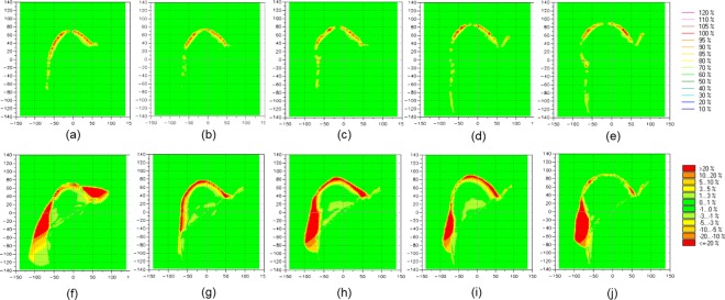
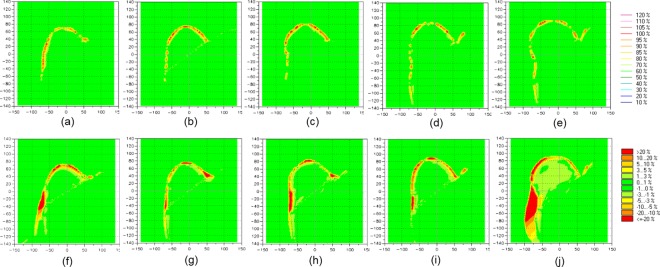
The planar dose distributions of Plan_VB using the virtual water-equivalent bolus were compared to dose planes calculated of treatment plans using PLA bolus and Super-Flex bolus, respectively. Two bolus thicknesses of 3 and 5 mm were then used in treatment planning. Fig 2 shows the comparison of the dose distribution in treatment planning using a 3 mm thick bolus. Compared to Plan_PLA, the dose difference was shown in the bolus area. The PLA bolus was set to high density material as 274 HU and a thickness was thinner than that of water. Thus, the higher dose was absorbed in the PLA bolus compared to a water-equivalent bolus. The larger volume of the breast shows the greater number of points of the dose difference. It is merely the difference to bolus size to cover the breast. Plan_PLA shows no difference in dose to the target of a whole breast. However, compared to Plan_bolus, the dose difference due to unwanted air gaps was shown within bolus and breast. The dose difference under the bolus was more than 20% of a normalization value of the prescription for all attachments. The air gap reduced the dose uniformity to the breast and the difference was less than 5% with no impact on the volume size. Fig 3 shows the comparison of the dose distribution in treatment planning using a 5 mm thick bolus. Compared to Plan_PLA, the dose difference was also shown in the bolus area. There was no differences according to the bolus thickness. However, compared to Plan_bolus, the dose difference between bolus and breast decreased compared to 3 mm bolus. A heavier bolus may be described that serve to reduce the air gap through better contact. The numerical data representing percentage of dose difference less than 3% between Plan_PLA and Plan_VB, and Plan_bolus and Plan_VB for all volumes of attachments are shown in Table 2. The mean percentages of dose difference less than 3% for comparison between Plan_PLA and Plan_VB (91.5% and 91.4% for 3- and 5-mm-thick bolus, respectively) were higher than those for comparison between Plan_bolus and Plan_VB (72.9% and 82.0% for 3- and 5-mm-thick bolus, respectively) with statistical significance (p < 0.001). There is a good agreement between the dose distribution for the virtual bolus and PLA bolus.
Fig 2.
The difference of the dose distribution between Plan_VB and Plan_PLA for (a) 200 cc,(b) 300 cc,(c) 400 cc, (d) 500 cc, (e) 650 cc attachments, and between Plan_VB and Plan_bolus for (f) 200 cc, (g) 300 cc, (h) 400 cc, (i) 500 cc, (j) 650 cc attachments using 3-mm-thick bolus.
Fig 3.
The difference of the dose distribution between Plan_VB and Plan_PLA for (a) 200 cc,(b) 300 cc,(c) 400 cc, (d) 500 cc, (e) 650 cc attachments, and between Plan_VB and Plan_bolus for (f) 200 cc, (g) 300 cc, (h) 400 cc, (i) 500 cc, (j) 650 cc attachment using 5-mm-thick bolus.
Table 2. Percentage of dose difference less than 3% between Plan_PLA and Plan_VB, and Plan_Bolus and Plan_VB for 200 cc, 300 cc, 400 cc, 500 cc and 650 cc attachments using 3- and 5-mm-thick bolus.
| 3-mm-thick bolus | 5-mm-thick bolus | |||
|---|---|---|---|---|
| Plan_PLA vs. Plan_VB | Plan_bolus vs. Plan_VB | Plan_PLA vs. Plan_VB | Plan_bolus vs. Plan_VB | |
| 200 cc | 87.8 | 65.2 | 88.9 | 79.9 |
| 300 cc | 91.8 | 72.1 | 91.4 | 86.6 |
| 400 cc | 91.5 | 72.4 | 90.4 | 83.8 |
| 500 cc | 93.2 | 76.2 | 93.0 | 84.2 |
| 650 cc | 93.1 | 78.7 | 93.5 | 75.6 |
| Mean | 91.5 | 72.9 | 91.4 | 82.0 |
Skin dose measurement
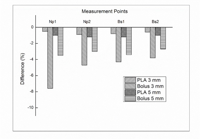
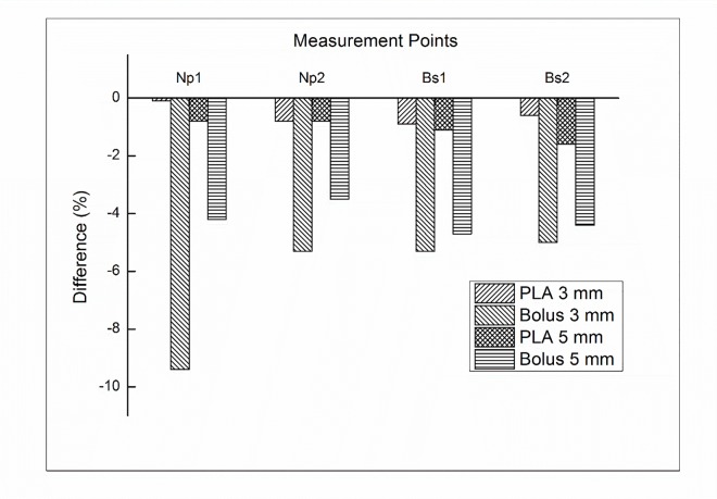
In addition to dose difference in treatment plan comparison, we further investigated the uncertainty of bolus replacement by measuring the skin dose. Fig 4 shows the percentage difference between calculated and measured doses in 200 cc breast attachment. With PLA bolus of 3 mm, the difference was not significant, which ranged from -0.5% to -0.9%. The average difference in PLA bolus of 5 mm was -1.1%. There was no impact on the volume size. With the Super-Flex bolus, however, significant dose differences were observed. With 3 mm bolus, the average difference was -5.1%, which ranged from -3.8% to -7.6%. With 5 mm bolus, the dose difference was reduced compared to that of 3 mm bolus. The average difference was -3.2%, which ranged from -2.7% to -3.5%. There was still no impact on the volume size. For a 300 cc breast attachment, the average differences were not significant for PLA bolus, which were -0.6% and -1.1% for 3 mm and 5 mm, respectively. With the Super-Flex bolus, the average differences were -6.3% and -4.2% for 3 mm and 5 mm bolus, respectively. The results of the dose difference for a 300 cc breast attachment were shown in Fig 5. The negligible air gap under PLA bolus showed a good agreement between calculated and measured doses regardless of the bolus thickness and breast size. The Super-Flex bolus of 5 mm reduced more air gaps compared to 3 mm bolus due to bolus weight. As a result of the dose difference, the negative values mean that unwanted air gaps make under dose in the measurement.
Fig 4. The percentage difference between the calculated and measured doses for Plan_PLA and Plan_bolus with a 200 cc attachment at both sides of the nipple (Np) and breast surface (Bs).
Fig 5. The percentage difference between the calculated and measured doses for Plan_PLA and Plan_bolus with a 300 cc attachment at both sides of the nipple (Np) and breast surface (Bs).
Discussion
High energy photon beams have a low dose at the skin surface, which is known as the skin sparing effect. The surface dose predominantly depends on photon beam energy [20, 21]. To cover the tumor which is near the surface, a bolus is used to increase the surface dose. However, commercial flat boluses cannot perfectly contact with the irregular surface, which makes an unwanted air gap between bolus and skin. This air gap significantly affect the surface dose [22]. The bolus routinely is used for radiation therapy of breast cancer. An unwanted air gap might be unavoidable in the daily setup. Moreover, variations in air gaps cannot be predicted in treatment planning. Thus, there is the dose discrepancy between calculated and delivered doses.
This study investigated the feasibility and advantages of a solid breast bolus made using a 3D printer technique. The printing material was the clear-PLA, which had been evaluated in previous other studies as a bolus material [23]. The bolus structure for printing was generated automatically above the body structure following the shape of the patient’s skin in the TPS. The TPS defines the body structure based on the CT image with HU threshold values. A characteristic of all imaging methods is that there is some blurring that occurs within the process. In the CT imaging process, there are several sources of blurring that collectively limit visibility of detail [24, 25]. There was no blurring effect by breathing since the anthropomorphic phantom was used in this study. However, there was still blurred images for the anthropomorphic phantom due to other sources during the imaging process. The blurred boundaries of CT images were included in the body structure. In this study, thus, the appropriate HU threshold value was investigated. The HU value of -950 seems appropriate to print a good fit of PLA bolus.
All of the printed PLA boluses were negative molds and rigid boluses. The breast volumes of bigger than 400 cc are droopy breasts in the anthropomorphic phantom model used in this study. The 3D-printed PLA bolus could not fit the breast attachments bigger than 400 cc because the PLA boluses were not flexible and those breast attachments were also rigid and had breast sagging (ptosis). For the patient with droopy breasts, however, the 3D-printed breast bolus might be applied for radiation treatment in the prone position because human’s breasts feature flexible.
In the case of postmastectomy radiotherapy without reconstruction in breast cancer, commercial bolus is often used to deliver the uniform dose distribution to chest wall [26, 27]. After the mastectomy without breast reconstruction, breast volume is less than 200 cc which may result in small air gap between bolus and patient’s skin. It is different experimental situation from this study. Further study validating the PLA bolus in case of breast volume less than 200 cc will be performed as a future work.
Using 3D printer techniques for radiation therapy have been gaining interest and the clinical efficacy have been investigated in several studies including this study. The 3D printing technique allows to manufacture the patient-specific bolus at low cost. PLA material of one kg used in this study is cheap (less than 30$) and can make two 5-mm-thick bolus. It have taken 12 hours to manufacture one PLA bolus. In order to implement the 3D-printed bolus in a clinic, however, practical problems should be considered such as a clinical process, space, and human resources. Furthermore, the patient may feel discomfort due to the hardness of the plastic bolus which is also limited to sensitive skin or open wounds and 3D-printed PLA bolus may be not well fitted to patient’s skin when patients breathe during treatment. Further work will investigate the soft patient-specific bolus using natural organic polymers such as glucomannan, curdlan, and gelatin to fix these limitation in clinic [8]. At that time, the 3D printer will manufacture the molding box for a patient-specific bolus. In this study, the measurements were performed for only anthropomorphic female phantom. It is important to evaluate the effect of 3D-printed PLA boluses on dose distribution in real cases for daily treatments. Further study evaluating 3D-printed PLA bolus in the case of anatomical modification will be performed with showing statistical analysis.
Conclusions
The 3D-printed solid bolus was applied to breast radiotherapy. This bolus can reduce the uncertainty of the daily setup and help to overcome the dose discrepancy due to unwanted air gaps. This negative 3D printing mold has a good fit against the irregular breast except for the folded breast. The 3D-printed bolus could replace currently used commercial boluses.
Supporting Information
(DICOM)
(ZIP)
Acknowledgments
This research was supported by grant no. 04-2015-0890 from the Seoul National University Hospital Research Fund.
Data Availability
All relevant data are within the paper and its Supporting Information files.
Funding Statement
This research was supported by a grant of the SNUH Research Fund (grant number: 04-2015-0890). The funder had no role in study design, data collection and analysis, decision to publish, or preparation of the manuscript.
References
- 1.Mihaylov IB, Penagaricano J, Moros EG. Quantification of the skin sparing effect achievable with high-energy photon beams when carbon fiber tables are used. Radiother Oncol. 2009;93: 147–152. 10.1016/j.radonc.2009.05.008 [DOI] [PubMed] [Google Scholar]
- 2.Sung W, Park JM, Choi CH, Ha SW, Ye S. The effect of photon energy on intensity-modulated radiation therapy (IMRT) plans for prostate cancer. Radiat Oncol J. 2012;30: 27–35 10.3857/roj.2012.30.1.27 [DOI] [PMC free article] [PubMed] [Google Scholar]
- 3.Loevinger R. A formalism for calculation of absorbed dose to a medium from photon and electron beams. Med Phys. 1981;8: 1–12. 10.1118/1.594901 [DOI] [PubMed] [Google Scholar]
- 4.Turner JY, Zeniou A, Williams A, Jyothirmayi R. Technique and outcome of post-mastectomy adjuvant chest wall radiotherapy-the role of tissue-equivalent bolus in reducing risk of local recurrence. Br J Radiol. 2016: 20160060 10.1259/bjr.20160060 [DOI] [PMC free article] [PubMed] [Google Scholar]
- 5.Andic F, Ors Y, Davutoglu R, Baz Cifci S, Ispir EB, Erturk ME. Evaluation of skin dose associated with different frequencies of bolus applications in post-mastectomy three-dimensional conformal radiotherapy. J Exp Clin Cancer Res. 2009;28: 41 10.1186/1756-9966-28-41 [DOI] [PMC free article] [PubMed] [Google Scholar]
- 6.Hsu SH, Roberson PL, Chen Y, Marsh RB, Pierce LJ, Moran JM. Assessment of skin dose for breast chest wall radiotherapy as a function of bolus material. Phys Med Biol. 2008;53: 2593–2606. 10.1088/0031-9155/53/10/010 [DOI] [PubMed] [Google Scholar]
- 7.Cho JH, Cho KH, Keum K, Han Y, Kim YB, Chu SS, et al. The benefit of individualized custom bolus in the postmastectomy radiation therapy: numerical analysis with 3-D treatment planning. Radiat. Oncol. J. 2003;21: 82–93. [Google Scholar]
- 8.Vyas V, Palmer L, Mudge R, Jiang R, Fleck A, Schaly B, et al. On bolus for megavoltage photon and electron radiation therapy. Med Dosim. 2013;38: 268–273. 10.1016/j.meddos.2013.02.007 [DOI] [PubMed] [Google Scholar]
- 9.Butson MJ, Cheung T, Yu P, Metcalfe P. Effects on skin dose from unwanted air gaps under bolus in photon beam radiotherapy. Radiat Meas. 2000;32: 201–204. [Google Scholar]
- 10.Su S, Moran K, Robar JL. Design and production of 3D printed bolus for electron radiation therapy. J Appl Clin Med Phys. 2014;15: 4831 10.1120/jacmp.v15i4.4831 [DOI] [PMC free article] [PubMed] [Google Scholar]
- 11.Gupta T, Mallik S, Master Z, Phurailatpam R, Laskar S. Brain-sparing holo-cranial radiotherapy: a unique application of helical tomotherapy. Clin Oncol (R Coll Radiol). 2011;23: 86–94. [DOI] [PubMed] [Google Scholar]
- 12.Kudchadker RJ, Antolak JA, Morrison WH, Wong PF, Hogstrom KR. Utilization of custom electron bolus in head and neck radiotherapy. J Appl Clin Med Phys. 2003;4: 321–333. 10.1120/1.1621494 [DOI] [PMC free article] [PubMed] [Google Scholar]
- 13.Kudchadker R, Antolak J, Morrison W, Hogstrom K. Conformal head and neck radiotherapy using custom electron bolus. Med Phys. 2002;29: 1337. [DOI] [PMC free article] [PubMed] [Google Scholar]
- 14.Low DA, Starkschall G, Sherman NE, Bujnowski SW, Ewton JR, Hogstrom KR. Computer-aided design and fabrication of an electron bolus for treatment of the paraspinal muscles. Int J of Radiat Oncol Biol Phys. 1995;33: 1127–1138. [DOI] [PubMed] [Google Scholar]
- 15.Perkins GH, McNeese MD, Antolak JA, Buchholz TA, Strom EA, Hogstrom KR. A custom three-dimensional electron bolus technique for optimization of postmastectomy irradiation. Int J of Radiat Oncol Biol Phys. 2001;51: 1142–1151. [DOI] [PubMed] [Google Scholar]
- 16.Zou W, Fisher T, Zhang M, Kim L, Chen T, Narra V, et al. Potential of 3D printing technologies for fabrication of electron bolus and proton compensators. J Appl Clin Med Phys. 2015;16: 4959 10.1120/jacmp.v16i3.4959 [DOI] [PMC free article] [PubMed] [Google Scholar]
- 17.Burleson S, Baker J, Hsia AT, Xu Z. Use of 3D printers to create a patient-specific 3D bolus for external beam therapy. J Appl Clin Med Phys. 2015;16: 5247 10.1120/jacmp.v16i3.5247 [DOI] [PMC free article] [PubMed] [Google Scholar]
- 18.Yoon MS, Kim Y, Jeong J, Nam T, Ahn S, Chung W, et al. Analysis on the dosimetric characteristics of tangential breast intensity modulated radiotherapy. Prog Med Phy. 2012:23: 219–228 [Google Scholar]
- 19.Park JM, Lee J, Kim HS, Ye SJ, Kim JI. Development of an applicator for eye lens dosimetry during radiotherapy. Br J Radiol. 2014; 87. [DOI] [PMC free article] [PubMed] [Google Scholar]
- 20.Klein EE, Esthappan J, Li Z. Surface and buildup dose characteristics for 6, 10, and 18 MV photons from an Elekta Precise linear accelerator. J Appl Clin Med Phys. 2003;4: 1–7. 10.1120/1.1520113 [DOI] [PMC free article] [PubMed] [Google Scholar]
- 21.Lamb A, Blake S. Investigation and modelling of the surface dose from linear accelerator produced 6 and 10 MV photon beams. Phys Med Biol. 1998;43: 1133–1146. [DOI] [PubMed] [Google Scholar]
- 22.Khan Y, Villarreal-Barajas JE, Udowicz M, Sinha R, Muhammad W, Abbasi AN, et al. Clinical and Dosimetric Implications of Air Gaps between Bolus and Skin Surface during Radiation Therapy. J Can Ther. 2013;04: 1251–1255. [Google Scholar]
- 23.Burleson S, Baker J, Hsia AT, Xu ZG. Use of 3D printers to create a patient-specific 3D bolus for external beam therapy. J Appl Clin Med Phys. 2015;16: 166–178. [DOI] [PMC free article] [PubMed] [Google Scholar]
- 24.Tarver RD, Conces DJ Jr., Godwin JD. Motion artifacts on CT simulate bronchiectasis. Am J Roentgenol. 1988;151: 1117–1119. [DOI] [PubMed] [Google Scholar]
- 25.Arac M, Oner AY, Celik H, Akpek S, Isik S. Lung at thin-section CT: influence of multiple-segment reconstruction on image quality. Radiology. 2003;229: 195–199. 10.1148/radiol.2291020642 [DOI] [PubMed] [Google Scholar]
- 26.Park K, Park S, Jeon MJ, Choi J, Kim JW, Cho YJ et al. Clinical application of 3D-printed-step-bolus in post-total-mastectomy electron confromal therapy. Oncotarget. 2016; 1–9. [DOI] [PMC free article] [PubMed] [Google Scholar]
- 27.Blitzblau RC, Horton JK. Treatment planning technique in patients receiving postmastectomy radiation therapy. Pract Radiat Oncol. 2013;3: 241–248. 10.1016/j.prro.2012.09.004 [DOI] [PubMed] [Google Scholar]
Associated Data
This section collects any data citations, data availability statements, or supplementary materials included in this article.
Supplementary Materials
(DICOM)
(ZIP)
Data Availability Statement
All relevant data are within the paper and its Supporting Information files.


