Abstract
In Electrical Impedance Tomography (EIT), we apply patterns of currents on a set of electrodes at the external boundary of an object, measure the resulting potentials at the electrodes, and, given the aggregate data set, reconstruct the complex conductivity and permittivity within the object. It is possible to maximize sensitivity to internal conductivity changes by simultaneously applying currents and measuring potentials on all electrodes but this approach also maximizes sensitivity to changes in impedance at the interface. We have therefore developed algorithms to assess contact impedance changes at the interface as well as to efficiently and simultaneously reconstruct internal conductivity/permittivity changes within the body. We use simple linear algebraic manipulations, the generalized SVD, and a dual-mesh finite-element-based framework to reconstruct images in real time. We are also able to efficiently compute the linearized reconstruction for a wide range of regularization parameters and to compute both the Generalized Cross-Validation (GCV) parameter as well as the L-curve, objective approaches to determining the optimal regularization parameter, in a similarly efficient manner. Results are shown using data from a normal subject and from a clinical ICU patient, both acquired with the GE GENESIS prototype EIT system, demonstrating significantly reduced boundary artifacts due to electrode drift and motion artifact.
I. Introduction
In Electrical Impedance Tomography (EIT), we can maximize sensitivity to changes in conductivity and permittivity deep within the body by simultaneously applying currents and measuring voltages on all electrodes [1], or, more specifically, by applying the eigen-currents of the Dirichlet-to-Neumann map. By doing so, though, we tend to also maximize our sensitivity to changes in impedance that occur at the interface between the electrodes and the body. An alternate approach is to use “four-electrode” measurements by applying current through adjacent electrodes and measuring on non-current-carrying electrodes [2]. In this case sensitivity to electrode impedance changes is reduced but the current density is primarily concentrated near the surface of the body, reducing the sensitivity to changes deep within the body. An ideal approach would give us high sensitivity to internal changes while also being robust to changes at the electrode-skin interface.
EIT has been proposed for a number of distinct applications from breast cancer screening [3], [4], [5] to monitoring of hydration [6] to lung ventilation [7], [2]. A review of the history, methods, and applications of EIT can be found in the text by Holder [8]. EIT can be performed in a number of modes: in absolute imaging, the goal is to compute a three-dimensional model of the three-dimensional conductivity and permittivity, typically by comparing the measured data to some sort of numerical or analytical “forward model.” In contrast, for difference-imaging, we only wish to reconstruct changes in the electrical properties of the body, assuming for example a homogeneous background distribution of properties. In difference-imaging, differences between voltages (or currents) measured on various electrodes over time are used as the inputs to the algorithm. Since the two measurements are affected by the same systematic errors due to electrode position uncertainty, absolute contact impedance and other factors, this imaging mode tends to be quite robust to these sources of error, which largely cancel-out in the subtraction. While this imaging approach, which has been generally used for lung monitoring, is typically robust to mis-estimation of body shape, electrode positions, and absolute electrode contact impedance variations, it is less robust to changes that happen simultaneously with the imaging, for example changes in the quality of each electrode’s contact with the body over time. The subject of this paper is difference-imaging where we attempt to compensate for some of these time-varying electrode-contact changes.
A number of electrode models have been suggested for use in EIT [9], [10] and it appears that the model with the most practical utility is the “complete electrode model” (CEM), introduced in [10] and further studied in [11], [12], [13], [14]. However, the superiority of this model has been primarily demonstrated with saline tank and phantom studies. Using human subject data, we will show the utility of this model for estimating changes that are happening in some small neighborhood of the electrodes and removing their effect from the conductivity reconstructions. Mathematically, the existence and uniqueness of the forward solution to the CEM model equations has been demonstrated [14].
In the field of solid-state physics the term “contact impedance” has a specific meaning related to the energy potential that needs to be overcome at the interface between for example a metal contact and a semiconductor substrate. In the case of imaging the body with EIT, the physics of the problem is significantly more complicated. The charge carriers in the electronic circuitry are electrons and the body contains various types of ions (chloride, sodium, potassium, etc…). Complex electrochemistry takes place at the interface of the electrodes, for example silver chloride [15], and the body. Similarly the skin has a complex three-dimensional multi-layered structure. We have found it useful to model all of the phenomena at the interface of each electrode and the skin with a single complex, time-varying parameter which we will refer to as its “contact impedance” keeping in mind that physically this parameter is the result of the aggregation of a number of distinct physical phenomena. We thus propose to use the current patterns that maximize distinguishability due to internal changes [1] while estimating and compensating for changes at the interface between the skin and the body using the complete electrode model. Changes in what we call “contact impedance” may be due to ion diffusion gradients, electrode motion, perspiration, contact gel, double-layer boundary effects, or changes in skin temperature, all of which serve to modulate the quality of current transfer through the electrodes and into the skin. To a lesser extent we may also be compensating for imperfections in the system hardware, for example drift in the applied currents over time.
There has been previous work on simultaneously estimating electrode contact impedances using the CEM and a medium’s internal admittivity. Kolehmainen and co-workers [16] demonstrated the sensitivity of the static imaging reconstruction using the CEM to errors in the assumed value of the contact impedance. The theory underlying the problem of simultaneous reconstruction of images and estimation of contact impedances was described in a report by Vilhunen and co-workers in 2002 [17]. The results shown were for a saline tank test cell with metal electrodes. In a follow-up publication, the same group [18] formulated the inverse problem as one of Bayesian estimation, incorporating regularization of the estimated image. They confirmed the results in a saline tank phantom with metal electrodes. The methods described in our current paper are based on a linearization assumption. The validity of this assumption has previously been validated for EIT determining the support of an inclusion in a piecewise-constant medium [19] but we are not aware of results on unique estimation of internal admittivities and contact impedances. In our current work, as the focus is on difference-imaging with a reference point close-by in time, we believe that the linearization assumption is warranted.
In a previous article, we described an approach to compensating for electrode contact quality using the complete electrode model in the context of absolute imaging [20]. There we showed that we could simultaneously estimate the contact impedances of all electrodes simultaneously with the image reconstruction, including compensating for the partial occlusion of one or more electrodes. More recently, Nissinen [21] reported on an algorithm for simultaneously estimating unknown contact impedances and unknown boundary shape, again in the context of absolute imaging. All of the above-referenced works relate to absolute or “static” imaging. Here, we consider the problem of difference or dynamic imaging where the region being imaged and contact impedances are both changing over time and show results for human subjects in vivo.
In what follows, we will describe efficient algorithms for simultaneously estimating time-varying electrode contact impedances and generating reconstructions using the complete electrode model. First, we will consider the case of reconstructing a single global impedance (or a small number of regional impedances). In this case, no regularization may be necessary, although it could be introduced to further constrain the solution. We then consider the case of reconstructing the spatial distribution of conductivity and permittivity, a problem requiring regularization to reduce its ill-posedness. We show that it is possible, using the generalized singular value decomposition (GSVD) [22], to generate explicit formulas for the matrices used in the linearized reconstruction for all possible values of the regularization parameter. Using the GSVD, it is also possible to efficiently compute the generalized cross-validation (GCV) metric. As for any given regularization parameter we can easily compute the reconstruction solution, we can also easily compute the L-curve [23] which is a heuristic approach to choosing the regularization parameter that simultaneously minimizes the residual as well as some selected image penalty function.
The structure of this paper is as follows. In section II, we outline the mathematical structure of the problem and describe the dual-mesh reconstruction approach used. The complete electrode model is described mathematically in section III and we also outline how the forward model can be solved and how the Jacobian matrices can be generated using the finite-element model. We also describe the software used to generate the finite element meshes used in our human subject experiments. The image reconstruction algorithms are described in sections IV and V. Example results for a normal subject and an intensive care unit patient are in Section VI.
II. Mathematical Preliminaries
At each time, we assume a measurement vector, y(t), resulting from the application of K patterns of current on L electrodes, where typically K = L − 1 to form a complete set of measurement. We denote the measurement at time 0, y(0), to be the “reference” measurement. Furthermore, we assume that our medium is well-described by the CEM and that we are able to compute the Jacobian matrices with respect to the contact impedances and the internal medium admittivities using previously-described methods [11], [12]. In our modeling, we use the finite-element method with customized meshes refined at the electrodes and we compute the Jacobian matrix with respect to changes in conductivity on the basis of tetrahedral elements.
The FEM meshes required for reasonable forward modeling accuracy typically have hundreds of thousands to millions of elements. Reconstructing images using this many basis functions would be computationally very expensive. We therefore create a “coarse” mesh whose basis functions are composed of disjoint unions of the forward-modeling tetrahedral elements. In the simplest case, this coarse-scale mesh contains only a single basis function representing the global admittivity of the entire medium. More generally, we consider a matrix P whose columns are orthogonal and represent linear combinations of tetrahedral basis functions. Specifically, we can write:
| (1) |
where x(t) is the solution for the admittivity at time t, P is a matrix of size V × M where V is the number of fine-scale basis functions, M is the number of coarse-scale basis functions, and p(t) is an M × 1 column vector representing the solution in terms of coarse-scale basis functions at time t. In the simplest case, P is a column vector of all ones and p(t) is a scalar at each point in time representing the global complex admittivity of the entire medium. If we have prior information that the medium is composed of different regions, for examples two lobes of the lungs and the heart, we can then generate basis functions defined on the support of each of these regions, and solve for the admittivity within each of these regions at each point in time.
We use a simple agglomerative algorithm to create a coarse mesh from a fine mesh. We start with the original tetrahedral finite-element mesh generated by the finite-element meshing software and merge elements with nearest neighbors until a minimum volume threshold, Vt is reached. Specifically, we used Algorithm 1.
Algorithm 1.
Fine-to-coarse mesh refinement
| Initialize set of coarse mesh elements C with tetrahedral elements from mesh generation |
| for each c ∈ C do |
| compute V(c), the volume of c |
| compute N(c), the list of nearest neighbors of c |
| initialize L(c), the list of tetrahedral elements comprising c |
| end for |
| for each c ∈ C such that V (c) < Vt do |
| Merge c with the member of N(c) with the largest volume, m |
| Remove c from C |
| Update N(m) to include N(c): |
| Update members of N(c) to include m |
| Update members of N(c) to remove c |
| Update V (m) = V (c) + V (m) |
| Update L(m) = L(m) ∪ L(c) |
| end for |
We note that other merging criteria, for example based on combined element shape or extent can be considered and if we have a priori information about tissue boundaries then we can implement the constraint that we do not merge members of C, which are ultimately the basis functions used in the reconstruction, across tissue boundaries. We also note that the performance of this algorithm could be further optimized but that we achieve quite reasonable performance at present by first sorting the elements by volume in increasing order (eliminating smallest elements first.)
III. Numerical Modeling
To analyze the human subject data, we used the CEM as implemented by the EIDORS MATLAB software toolkit [24]. Jacobian matrices were computed using finite differences. However, as we shall see below, it is possible to explicitly compute the Jacobian matrices with respect to perturbations in either contact impedances or internal medium conductivities.
A. Mathematical description of the CEM
In EIT, we assume that the potential in the body is described by Poisson’s equation, which is derived from the quasistatic approximation to Maxwell’s equations with isotropic conductivities:
| (2) |
where u(p) is the scalar potential as a function of position, p.
Cheng, Isaacson et al. [10] introduced the CEM in which the electrodes, being highly conductive, are specified to be at a uniform potential, but where there is assumed to be a potential gradient between the electrodes and the medium being probed which can be quantified by a “contact impedance” parameter which is defined on a per-electrode basis:
| (3) |
| (4) |
| (5) |
Here eℓ is the support of electrode ℓ, Iℓ is the current injected into this electrode, Uℓ is the measured potential on this electrode, zℓ is the electrode contact impedance, and ν is the vector normal to the boundary.
The following additional constraints, which require that the currents and voltages over all electrodes sum to zero, are needed for existence and uniqueness of the forward solution [14]:
| (6) |
| (7) |
B. Numerical CEM Solution
The complete electrode model can be numerically solved using the Galerkin method, utilizing a set of test functions, υ, and representing both u(p), υ(p), and γ(p) as a linear combination of basis functions. The divergence theorem leads to the following relation:
| (8) |
Applying the boundary conditions, Eqs. 3 and 4, Eq. 8 can be rewritten as
| (9) |
Rewriting Eq. 5, we have
| (10) |
Substituting Eq. 10 into Eq. 9, we find that:
| (11) |
and substituting Eq. 10 into Eq. 3, we have
| (12) |
where ℓ = 1,2,…,L and |eℓ| is the area of ℓ-th electrode.
Finally, substituting Eq. 12 into Eq. 11, we have
| (13) |
This equation is discretized by approximating the potential u by a finite linear combination of basis functions φα and choosing test functions υ = φβ:
| (14) |
| (15) |
where B is the number of basis functions used in the discretization. For example, B is equal to the number of nodes in the mesh for linear finite elements.
In the finite-element method (FEM), u, υ, and γ are discretized by linear, quadratic, or even potentially higher-order basis functions defined on a mesh of nodes, with each basis function having compact support, and Eq. 13 reduces to a sparse linear system, which can be solved by either direct or iterative linear algebraic methods.
C. Finite-Element Meshing
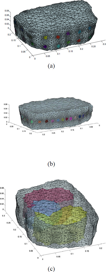
For the finite-element meshing, we use the CGAL [25] software package, using features in this package to increase the density of mesh elements near the electrodes. We create a finite-element mesh from a three-dimensional segmented magnetic resonance imaging (MRI) volume [26] as shown in Fig. 1. In our human-subject experiments, we experimented with several electrode configurations, and data from each of these configurations will be displayed in Section VI. Specifically, we use a single ring of 32 electrodes to maximize in-plane resolution, or two rings of 16 electrodes each to give 3-D resolution. The axes scaled in meters and the positions of the electrodes in the two configurations can be seen in Figs. 1 (a) and (b). If a patient-specific labeled imaging volume were available, for example from a computed tomography image or MRI, we could produce a personalized EIT mesh with identified sub-volumes denoting for example the heart and two lung lobes, as shown in Fig. 1 (c). Since no such images were available for our normal subjects, we used a homogeneous FEM mesh.
Fig. 1.
Finite element meshes used showing positions of electrodes and refinement of mesh near electrodes for two electrode configurations: (a) Two rings of 16 electrodes each (b) Single ring of 32 electrodes (c) Mesh with transparency showing capability of developing a patient-specific mesh given a labeled volume.
IV. Reconstruction without Regularization
If we are only reconstructing the value of a single “pixel” or a small number of basis function coefficients at each time point, then it is possible that the problem is sufficiently well-posed, even taking into account contact impedances, that we can compute the solution without the need for explicit regularization. In this case, we assume the following model:
| (16) |
where Jγ is the Jacobian matrix with respect to fine-scale FEM tetrahedra, Jz is the Jacobian matrix with respect to contact impedances on the electrodes (with dimension LK ×L), z(t) is a column vector of contact impedances at time t, n(t) is a column vector of noise measurements and y(t),y(0) are the measurement vectors at times t and 0, respectively. We reiterate that L is the number of electrodes and K is the number of patterns applied. In what follows, we simplify matters by introducing the following notation: Jp = JγP, where P is the fine-to-coarse basis function transformation matrix.
In this case, we can show, with the assistance of some linear algebra, that the least-squares solution for p(t) is as follows:
| (17) |
where is the Hermitian transpose of the matrix Jp and I is the identity matrix of the appropriate size. Specifically, we derive this equation as follows:
| (18) |
and, as usual for least-squares problems, multiply both sides by the transpose of the left-hand side:
| (19) |
We then obtain the following expression for change in contact impedances at time t by solving the first equation of the system of equations 19:
| (20) |
We finally obtain Eq. 17 by substituting Eq. 20 into the second equation of the system of equations 19 and solving for p(t):
| (21) |
We can further simplify Eq. 17 by computing the singular value decomposition (SVD) of the matrix Jz: . Given the SVD, we can show the following:
| (22) |
We then define: , where I is the identity matrix, as the operator projecting the data onto the null space of the Jacobian matrix with respect to the contact impedances. Finally, one can show that:
| (23) |
Once we have computed p(t), we then compute the changes in contact impedances at time t as follows:
| (24) |
We note that this expression can similarly be simplified using the SVD of Jz.
V. Reconstruction with Regularization
In the case where p(t) has relatively high dimension on the order of hundreds or thousands of basis functions, we do not choose the least-squares solution of z(t) and p(t), as it highly sensitive to even extremely small noise levels. Instead we find some trade-off between minimizing the residual and minimizing some property of the solution, for example its l2 norm, introducing a regularization term into the equations.
In what follows, we regularize p(t) and not z(t), as it is generally the case that the condition number of Jz is reasonably small.
The regularized simultaneous solution of the contact impedances and medium admittivities are expressed as follows:
| (25) |
where the regularization parameter is λ and L is a regularization operator. In what follows, for L we use the graph Laplacian [27] with a weight of unity if two coarse-scale elements of p are nearest neighbors as determined by an algorithm such as Algorithm 1 and zero otherwise.
This equation is equivalent to the solution of the following matrix system in a least-squares sense:
| (26) |
Using an analogous approach to that described in Section IV, we can show that the least squares solution to this system of equations is:
| (27) |
In what follows, we use the fact that NHN = N. We then compute the GSVD [22] of (NJp,L) as follows:
| (28) |
| (29) |
Finally, it can be shown that, for any value of the regularization parameter, the solution for p(t) is:
| (30) |
where C and S are diagonal matrices, X is a full-rank typically well-posed matrix whose inverse can be precomputed (for the purposes of generating the solution for any value of the regularization parameter) and U is an orthonormal matrix.
A number of approaches have been suggested for selection of the optimal value of the regularization parameter. One widely-cited and utilized method, generalized cross-validation (GCV) [28] generalizes the procedure of n-fold cross-validation, where data points are ”held out” from the solution we examine the residual between the true and predicted values of these held-out data points. The expression for the GCV functional is as follows:
| (31) |
where, in our case, y = y(t) − y(0). For the case of simultaneous imaging and contact impedance estimation, the matrix, A(λ) is given by the following expression:
| (32) |
Heuristically, the GCV functional attempts to find a tradeoff between minimizing the residual, ‖y(t) − y(0) − Jzz(t) − Jpp(t)‖2, given by its numerator, and mitigating the extent to which random noise is amplified in the reconstruction, given by its denominator.
We can compute the numerator of V (λ) using the GSVD and Equations 30 and 24. From the standpoint of computation, only the numerator of V (λ), which is the norm of the residual, is significant and can be relatively easily computed using the GSVD. The denominator does not depend at all on the data, y, and so can be pre-computed for all possible candidate values of the regularization parameter.
VI. Results and Discussion
At GE Global Research, we have developed a prototype EIT instrument, the GE GENESIS system, with 32 independent high-output-inpedance current sources, presently operating at a single frequency, 10 kHz. A safety circuit monitors the total applied current in real-time and interrupts operation if the current exceeds established safe limits for this frequency. We simultaneously apply currents on each channel and measure voltages using matched filter detection and 16-bit high-precision Analog-to-Digital Converters (ADCs). The matched filter produces both in-phase and quadrature components for each measurement.
A. Normal Subject Study
We studied healthy, adult volunteers with the approval of an outside institutional review board (IRB) provided by Ethical and Independent Review Services and after obtaining informed consent. A single ring of 32 standard ECG electrodes (Intelesens Ltd. Belfast, Northern Ireland) was placed around the circumference of the chest at approximately the fifth intercostal space and EIT data were collected at a frame rate of approximately 19 frames/sec. A complete set of trigonometric current patterns was applied during each data frame.
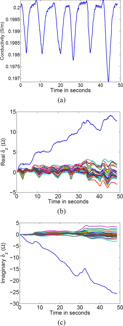
We first used Equations 23 and 24 to compute a single global conductivity and a set of contact impedances at each point in time. The results for a human subject, subject F78, during normal but deep breathing are shown in Fig. 2. The estimated changes in the real and imaginary parts of the contact impedances are shown in Figs. 2 (b) and 2 (c), respectively, where we note that the actual units of the contact impedance parameters are Ωm2 but we have divided by the electrode areas to give results in units of Ohms. This convention will be followed for the remainder of this article. In all of the reconstructions to follow, we computed the Jacobian matrices with an assumed homogeneous background conductivity of 0.2 S/m and with all electrodes having initial absolute contact impedances of 100 Ω.
Fig. 2.
Estimation of a single global time-varying conductivity (a) and time-varying electrode contact impedances (b) and (c).
The reference frame was taken at end-expiration and we see a sharp drop in conductivity with each inspiration. We also see changes in electrode contact impedances correlated with inspiration. Specifically, we see decreases in contact impedances during inspiration and increases during expiration. This effect may be due to the slight stretching of the skin in inspiration, which may recruit or expand pores through the epidermis. Finally, we notice that one particular electrode, which happens to be electrode 16, experienced a relatively large increase in contact impedance during the data collection.
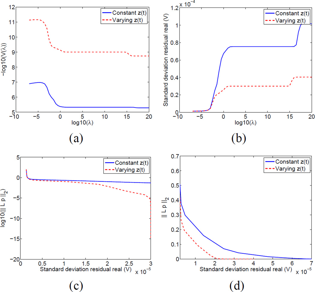
Next, we chose the data time point with the largest change in global conductivity in the first twenty seconds of data collection and computed the GCV functional over a wide range of potential regularization parameters, with the results shown in Fig. 3. We note that −log(V (λ)) reaches its maximum at almost precisely the same value where the residual reaches its leftmost asymptote, which represents the noise floor of the instrument. This noise floor of approximately 2 micro-volts RMS (root mean square) is consistent with results obtained with measurements of resistor phantoms. In Fig. 3 we compare the two approaches (reconstruction assuming constant contact impedances and reconstruction allowing contact impedances to vary over time) looking at the GCV functional as a function of regularization parameter in Fig. 3 (a). We compare the achievable residuals using the two approaches in Fig. 3 (b). The reconstructions represented in Fig. 3 (b) show several “phase transitions.” To the far right, for a very high regularization parameter, the solutions are identically zero. Then for a wide range of regularization parameter values, the solutions are spatially constant (i.e. with zero Laplacian). Finally, for smaller values of the regularization parameter, the solution has some spatial structure. The solutions where we reconstruct both changes in contact impedances and changes in the medium for all values of the regularization parameter achieve a lower value of the residual, notably so for the region from λ = 102 to λ = 1014 where the solutions are spatially constant.
Fig. 3.
GCV functional vs. regularization parameter (a) and residual standard deviation vs. regularization parameter (b) and L-curve analysis (c) over a wide range including “blow-up” at noise floor and (d) over a smaller range away from “blow-up” point
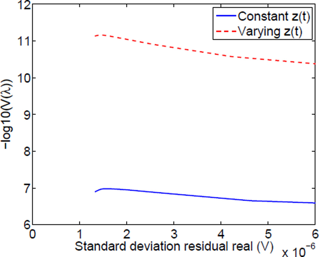
It is also instructive to consider the “L-curve” showing the tradeoff between the achievable reconstruction residual and the image penalty function, ‖Lp‖2, where in the case of the Laplacian, we are penalizing images with low smoothness. In comparing the two reconstruction approaches in Fig. 3 (c), with image penalty shown on a logarithmic scale, we see that when including contact impedance parameters, we can achieve a smoother image (lower penalty) for any given residual. We can choose an optimal regularization parameter in each case by looking at the L-curve not including the region where the penalty “explodes” at the noise floor in Fig. 3 (d). We choose regularization parameters achieving residuals of 15 micro-volts and 10 micro-volts, respectively, for the reconstructions with constant and static contact impedances as reasonable tradeoffs between minimizing image penalties and minimizing the residual. It is also interesting to look at the GCV functional vs. the residual, shown in Fig. 4. We find that this functional increases monotonically until we reach the noise floor, at approximately 1.8 micro-volts but that the optimal image quality, both by visual inspection and by examining the L-curve, is obtained at a higher value of the residual. We believe that the reason for this is that the derivation of the GCV functional is based on the assumption of purely independent, identically distributed Gaussian noise, whereas in reality we believe that the largest source of “noise” is the modeling error, for example computing the Jacobian matrix assuming a homogeneous background conductivity when the body is clearly far from being so and with all electrodes having the same initial absolute values of the contact impedances. The L-curve method better accounts for these realities.
Fig. 4.
Close examination of the GCV function vs. the residual
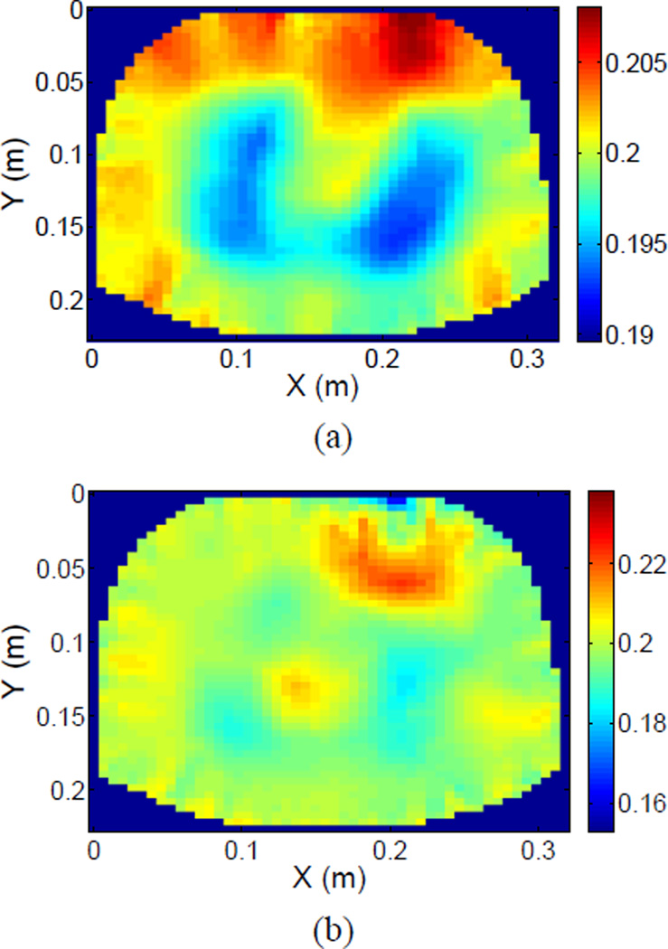
Finally, we computed reconstructions of the same data point, 42.16 seconds after the start of the data collection, under two assumptions. In the first case, we used the algorithms described earlier and computed an image as well as values for the changes in the electrode contact impedances. In the second case, we used the “standard” approach in which only an image was computed and the contact impedances on the electrodes were assumed to remain constant. The results are shown in Fig. 5. In Fig. 5 (a), where we have simultaneously computed an image and varying contact impedances, the two lobes of the lungs are clearly evident. In Fig. 5 (b), the lungs appear less evident, there are in general electrode artifacts and in particular there is a large negative artifact near electrode 16, at the top center right of the image.
Fig. 5.
Reconstruction assuming (a) Time-varying contact impedances and (b) Constant contact impedances
B. Clinical Study
A total 20 adult ICU subjects (10 Male, 10 Females, age: 49.05 16.32 years (mean standard deviation)) were studied in the intensive care unit (ICU) at Columbia University Medical Center, New York, NY after obtaining approval of the Institutional Review Board of Columbia University. Written informed consent was obtained from the subject or a family member if the subject was sedated. About one hour of impedance measurements for each ICU subject was collected at a carrier frequency of 10 kHz.
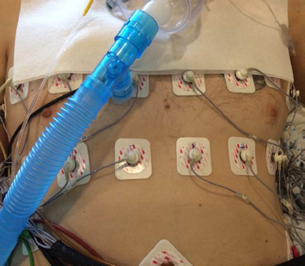
A comprehensive summary of our research results from this study will be presented elsewhere. Here, we will present results from a specific patient, Patient 119, for illustrative purposes. Adult subject 119 was Female, age: 22, chest circumference: 75 cm, body mass index (BMI): 14.1, with right lower lobe pneumonia and hypoxemia. EIT measurements were made in a 3D configuration (2 axial rings with 16 electrodes per ring) with the subject receiving mechanical ventilation in a semi-recumbent position (supine in bed with elevated backrest). The two electrode rings were at approximately the fourth and sixth intercostal spaces, as shown (for a representative male subject) in Fig. 6.
Fig. 6.
Electrode configuration for adult ICU subjects
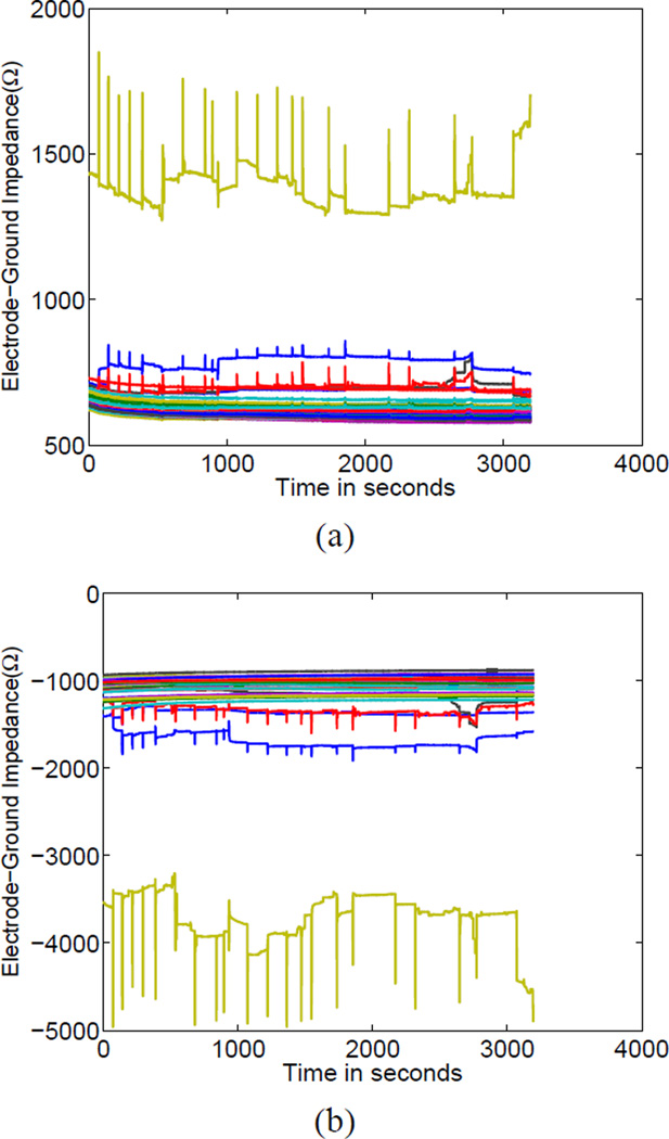
A particularly useful feature of the GENESIS system is that, interleaved with the optimal trigonometric excitation patterns used for producing high-quality images we also applied “electrode check” patterns sending current through each electrode to a distant ground electrode. In this way, we were able to assess the quality of each electrode’s contact in real time. We show the variation over time of all electrode-to-ground impedances in Fig. 7, where the real and imaginary parts of the impedance are shown in Fig. 7 (a) and (b), respectively. We noted that one electrode, electrode 20, was a significant outlier in terms of its impedance-to-ground, with a value of approximately 1500 Ω in the real part and −4000 Ω in its imaginary part, as compared to approximately 600 Ω and and −1500 Ω for the real and imaginary impedances-to-ground for all other electrodes. The GENESIS system is equipped with software to automatically adjust the gain of its analog preamplifier to prevent measurements from saturating but one consequence of this gain adjustment is that it is possible that effective signal-to-noise ratio was decreased due to increased quantization error as a result of this adjustment. Thus, in such cases, it may be beneficial to replace or somehow improve the contact of poorly contacting electrodes. We note in Fig. 7 the existence of a number of a large “spikes” in the impedance of several electrodes, which we attribute to motion artifact.
Fig. 7.
Electrode-to-distant-ground impedances measured nearly simultaneously with reconstruction data (a) Real part (b) Imaginary part
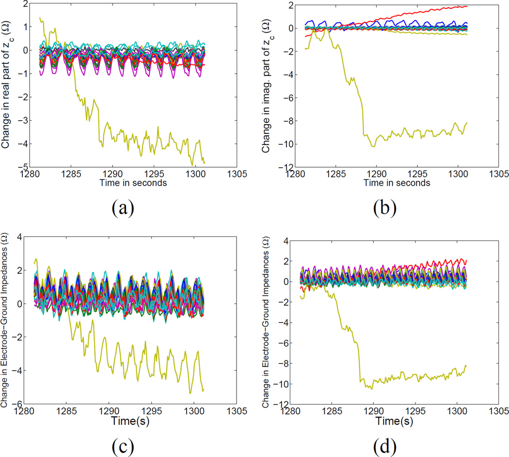
We have noted that the electrode contact impedances tended to drift significantly over time but at a relatively slow rate and that respiration and cardiac events occur at a much faster rate. We have thus chosen to process the data in 20-second non-overlapping “blocks” to minimize the effect of electrode drift over time. However, even within such a short time period, electrode impedance variations occur. One particular block of data, block 65, is shown in Fig. 8. In Fig. 8, we display the changes in the estimated electrode contact impedances, with the real and imaginary parts shown in Figs. 8 (a) and (b). The corresponding nearly simultaneously measured changes in electrode impedances to ground are shown, for the real and imaginary parts of the measurements, respectively, in Figs. 8 (c) and (d). We note the strong similarity between Figs. 8 (a) and (c) and also (b) and (d). In particular, the correlation coefficients between the real and imaginary parts of the changes in estimated impedances and the changes in the electrode impedances-to-ground for electrode 20 (the electrode experiencing the greatest change) were 0.97 and 0.998, respectively. We believe that the electrode-to-ground impedances are dominated by contact impedance variations but also contain the phenomena of interest, respiration and perfusion, and thus the two sets of parameters (estimated changes in impedances and measured changes in electrode impedances to ground) should not be identical. However, the strong similarity provides evidence attesting to the usefulness of the estimation algorithms.
Fig. 8.
Estimated changes in contact impedances estimated by the simultaneous reconstruction algorithm for block 65 of data collection: (a) Real part and (b) Imaginary part and measured changes in electrode-ground impedances: (c) Real part and (d) Imaginary part.
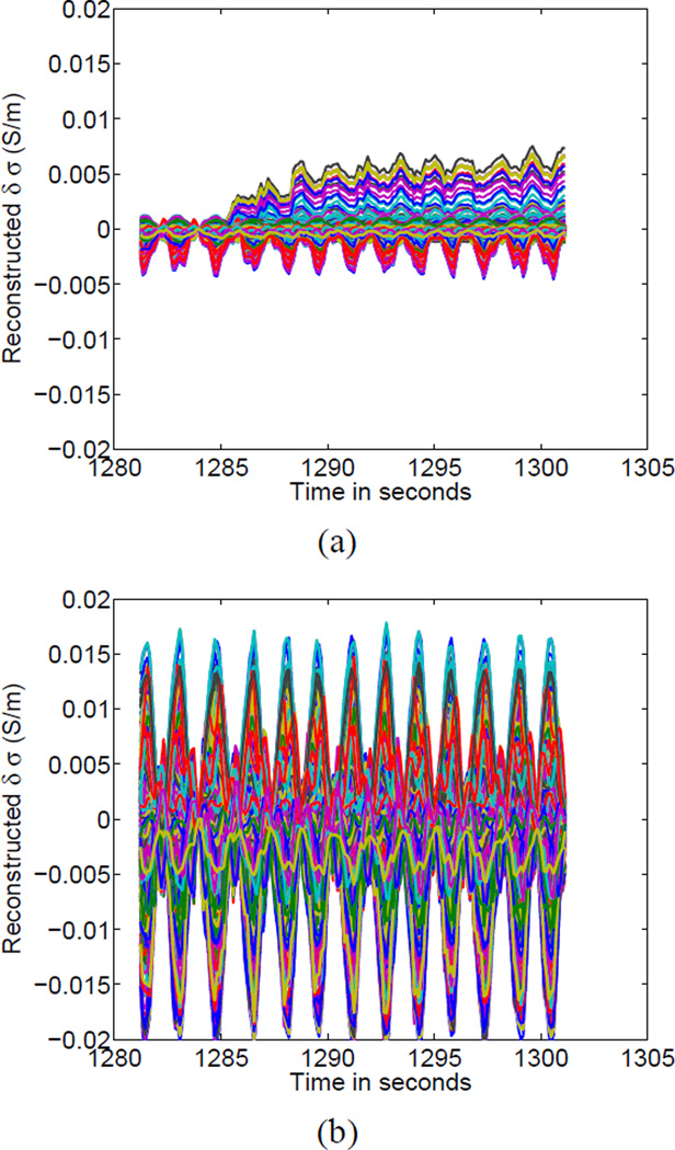
The reconstructions of block 65 of the clinical patient data, showing the evolution of all pixels over time are shown in Fig. 9. Fig. 9 (a) shows the reconstruction without assuming that contact impedances vary and thus we see that a number of pixels tend to “drift” over time. In contrast, for the reconstructions in Fig. 9 (b) in which the contact impedances shown in Fig. 8 were estimated, we see a repetitive pattern that is presumably due to respiration alone and where phenomena at the boundary were captured by the time-varying contact impedance parameters. Note that, as different regularization parameters were used for the two cases, the dynamic range of the estimated changes in conductivity due to respiration were different in the two cases, with larger changes estimated when we included contact impedances in the reconstruction.
Fig. 9.
Reconstructions of time courses for a given 20-second block of data (block 65) (a) Reconstructions of all pixels without simultaneous estimation of changing contact impedances (b) Utilizing simultaneous estimation of time-varying electrode-skin impedances.
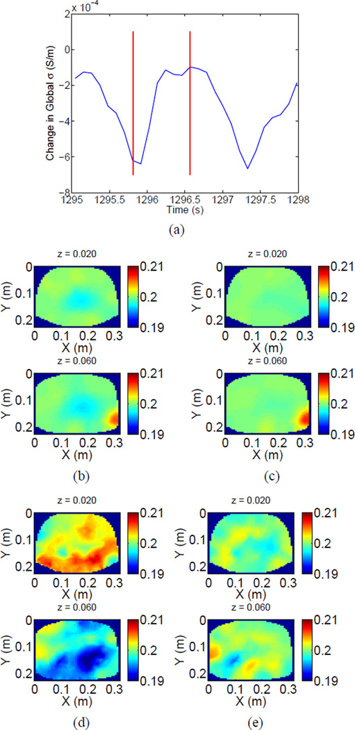
The images for the two cases are shown in Fig. 10. We show the estimated global conductivity for two ventilatory cycles in Fig. 10 (a) and the reconstructions at 1295.81 and 1296.57 seconds, respectively, with reference at 1282.4 seconds, assuming constant contact impedances, are shown in Fig. 10 (b) and (c). Vertical lines were added to Fig. 10 (a) to indicate the time points at which the reconstruction was computed. The corresponding case where we simultaneously estimate time-varying contact impedances for the same time points and the same reference point is shown in Figs. 10 (d) and (e). We point out that the reconstruction for each time point is composed of two rows with each row corresponding to an electrode ring. The z = 0.06 m electrode ring probes mainly the upper lobes of the lungs. We note that the images assuming constant contact impedances are completely dominated by a single poor electrode artifact. The time point at 1295.81 seconds, shown in Figs. 10 (b) and (d) corresponds to end-inspiration, with minimal global conductivity, while the time point at 1296.57, shown in Figs. 10 (c) and (e) corresponds to endexpiration, with maximal global conductivity. The reference was taken at approximately end-expiration, so the images for time point 1295.81 should and does show the largest changes in conductivity. As the respiration rate was greater than 40 breaths per minute, with correspondingly low tidal volume, the images are not quite as appealing as for the normal subject, but when we compute the reconstruction taking into account changes in contact impedances, we do see large regions of decreased conductivity for the end-inspiration time point primarily in the upper lung ring of electrodes (z = 0.06 m), consistent with mainly shallow breathing. In contrast, the reconstruction assuming constant contact impedances mainly shows the outlier electrode.
Fig. 10.
Global change in impedance (a) and (b),(c): Reconstructions at 1295.81 and 1296.57 seconds, respectively, with reference at 1282.4 seconds assuming constant contact impedances. (d),(e): Reconstructions at 1295.81 and 1296.57 seconds, respectively, with reference at 1282.4 seconds with simultaneous estimation of changes in contact impedances.
We finally note that for this particular block of data electrode 20 was the outlier with a change of 6.33 Ohms in the real part of its impedance over 20 seconds whereas the median change for all other electrodes was 0.57 Ohms. In the previous normal subject example, electrode 16 was the outlier and so there was not a systematic problem with one particular data channel. We have also found that the situation is highly variable: an electrode that is stable at one point in time may begin to vary at another point in time due to patient motion, perspiration, and other factors.
In order to examine this phenomenon more carefully, we chose a change in estimated contact impedance of greater than five Ohms in either the real or imaginary part of the measurement to be indicative of poor electrode quality. For subject 119, we counted the number of 20-second data blocks with varying numbers of poor-contact electrodes. There was a reasonable number of data blocks with no outlier electrodes (65/151 or 43%) but 86/151 or approximately 57% of the data blocks would need to be discarded if we did not employ an algorithm capable of dealing with one or more outliers. More realistically, the number of data blocks with a single outlier electrode was 40/151 or 26%, so based on the examples shown in this paper, we can reasonably conclude that many of these blocks could be recovered whereas they would possibly need to be discarded if we did not use the methods described here. It will be a subject of future research exactly how many poor-contact electrodes can be tolerated but relatively few data blocks (15/151 or 9.9%) contained more than three poorcontact electrodes.
Finally, we examined the issue of electrode quality for all of our clinical ICU subjects, excluding subject 102, for whom we were not able to reconstruct images or detect ventilatory activity, due to instrument noise problems. The results are shown in Table I, where, for each subject, we report the number of 20-second data blocks that passed our initial quality assessment mainly relating to saturation of analog-to-digital converters. For each subject we then report the numbers of 20-second blocks with 0,1,2,3, and more than 3 poorly contacting electrodes, where a poorly contacting electrode is defined as one where either the real part or imaginary part of the estimated contact impedance varied by greater than 5 Ohms. In total, we collected 3126 20-second data blocks that passed our initial quality assessment, corresponding to 17.37 hours of data. Of these, 1760 blocks (9.78 hours) had all electrodes varying by less than the specified 5-Ohm threshold. There were 364 data blocks (11.6% of the data) with one poorly contacting electrode but as we saw previously for subject 119, certain subjects had a much greater proportion of measurements with one poorly contacting electrode.
TABLE I.
Electrode quality results for all adult clinical ICU subjects
| Subject | Number of blocks | Blocks with poorly contacting electrodes | ||||
|---|---|---|---|---|---|---|
| 0 | 1 | 2 | 3 | more than 3 | ||
| 101 | 121 | 108 | 7 | 2 | 3 | 1 |
| 103 | 95 | 48 | 12 | 8 | 4 | 23 |
| 104 | 204 | 185 | 7 | 1 | 0 | 11 |
| 105 | 134 | 57 | 25 | 10 | 4 | 38 |
| 106 | 168 | 115 | 20 | 12 | 4 | 17 |
| 107 | 203 | 185 | 9 | 4 | 2 | 3 |
| 108 | 253 | 150 | 27 | 6 | 9 | 61 |
| 109 | 150 | 99 | 9 | 1 | 3 | 38 |
| 110 | 194 | 51 | 21 | 12 | 10 | 100 |
| 111 | 180 | 110 | 30 | 17 | 9 | 14 |
| 112 | 189 | 18 | 30 | 17 | 14 | 110 |
| 113 | 82 | 0 | 1 | 33 | 5 | 43 |
| 114 | 109 | 101 | 6 | 1 | 0 | 1 |
| 115 | 151 | 113 | 14 | 3 | 6 | 15 |
| 116 | 153 | 30 | 15 | 7 | 14 | 87 |
| 117 | 105 | 20 | 30 | 34 | 10 | 11 |
| 118 | 168 | 140 | 10 | 0 | 5 | 13 |
| 119 | 151 | 65 | 40 | 26 | 5 | 15 |
| 120 | 316 | 165 | 51 | 17 | 20 | 63 |
| Totals | 3126 | 1760 | 364 | 211 | 127 | 664 |
C. Discussion
Both the normal subject and clinical ICU subject data sets contained an “outlier” electrode. When placing 16 or 32 electrodes, it is very difficult to ensure that all electrodes maintain equally good contact with the body. It is unfortunately difficult to manipulate and position ICU patients, who are quite fragile and who often are sedated, in order to attach the electrodes. Therefore, even if it is noticed that one electrode has problems with contact, from the standpoint of the time that we have to conduct the experiment in the clinic, it may not be feasible to remove and reattach this electrode. Also, for reasons that are not well-understood, electrodes impedances may “drift” in different ways, with some electrodes experiencing more drift than others even if their initial contact impedances are reasonable. It is then advantageous to use algorithms that are immune to this drift or that at a minimum mitigate its effects and it was the goal of this paper to present such algorithms and validate their usefulness with real clinical data.
Although in our two examples we have shown the proposed method correcting for the variation in the impedance of a single outlier electrode, there is nothing inherent in the algorithm limiting it to only being able to correct single-electrode problems and to a certain extent we believe that it may be possible to compensate for the variation of multiple electrodes up to and including all electrodes.
VII. Conclusion
We have shown how to estimate contact impedances at the skin-electrode interface in EIT. These estimates are obtained simultaneously with reconstructing the internal conductivity and permittivity of the medium. We give explicit formulas for both solutions, with and without regularization. When regularization is used, we have also shown how to select an optimal value of the regularization parameter in a computationally efficient manner. Results of applying these methods were shown for a study two adults, a normal subject and an Intensive Care Unit patient. The results demonstrate the utility of these methods to reduce electrode-related artifacts in the reconstructed images.
For a small number of human subjects, several approaches to selecting the optimal regularization parameter were compared, with the L-curve giving a more appealing result than that obtained for the GCV metric. Over an extremely wide range of regularization parameters, the images where we simultaneously estimate changes in contact impedances are uniformly smoother than those where the contact impedances are assumed to remain constant.
Acknowledgments
We acknowledge our collaborators at University College, London, specifically David Holder and Kirill Aristovich, for guidance with finite-element meshing and mesh-refinement near the electrodes. We also thank the anonymous reviewers for their careful reading of this paper and for their many helpful suggestions.
This research was supported by Grant Number 1R01HL109854 from the National Institutes of Health. The content is solely the responsibility of the authors and does not necessarily represent the official views of the National Institutes of Health.
References
- 1.Isaacson D. Distinguishability of conductivities by electric current computed tomography. IEEE Trans. Med. Imag. 1986;5:92–95. doi: 10.1109/TMI.1986.4307752. [DOI] [PubMed] [Google Scholar]
- 2.Adler A, Amyot R, Guardo R, Bates J, Berthiaume Y. Monitoring changes in lung air and liquid volumes with electrical impedance tomography. Journal of Applied Physiology. 1997;83(5):1762–1767. doi: 10.1152/jappl.1997.83.5.1762. [DOI] [PubMed] [Google Scholar]
- 3.Cherepenin V, Karpov A, Korjenevsky A, Kornienko V, Mazaletskaya A, Mazourov D, Meister D. A 3D electrical impedance tomography (EIT) system for breast cancer detection. Physiol. Meas. 2001;22:9–18. doi: 10.1088/0967-3334/22/1/302. [DOI] [PubMed] [Google Scholar]
- 4.Kerner TE, Paulsen KD, Hartov A, Soho SK, Poplack SP. Electrical impedance spectroscopy of the breast: Clinical imaging resuls in 26 subjects. IEEE Trans. Med. Imag. 2005;25(5) doi: 10.1109/tmi.2002.800606. [DOI] [PubMed] [Google Scholar]
- 5.Soni N, Hartov A, Kogel C, Poplack SP, Paulsen KD. Multi-frequency electrical impedance tomography of the breast: new clinical results. Physiological Measurement. 2004;25:301–314. doi: 10.1088/0967-3334/25/1/034. [DOI] [PubMed] [Google Scholar]
- 6.Chen X, Kao T-J, Ashe JM, Boverman G, Sabatini JE, Davenport DM. Multi-channel electrical impedance tomography for regional tissue hydration monitoring. Physiological measurement. 2014;35(6):1137. doi: 10.1088/0967-3334/35/6/1137. [DOI] [PubMed] [Google Scholar]
- 7.Frerichs I, Schmitz G, Pulletz S, Schadler D, Zick G, Scholz J, Weiler N. Reproducibility of regional lung ventilation distribution determined by electrical impedance tomography during mechanical ventilation. Physiological Measurement. 2007;28(7):S261–S267. doi: 10.1088/0967-3334/28/7/S19. [DOI] [PubMed] [Google Scholar]
- 8.Holder DS. Electrical impedance tomography: methods, history and applications. CRC Press; 2004. [Google Scholar]
- 9.Hua P, Woo EJ, Webster JG, Tompkins WJ. Finite element modeling of electrode-skin contact impedance in electrical impedance tomography. Biomedical Engineering, IEEE Transactions on. 1993;40(4):335–343. doi: 10.1109/10.222326. [DOI] [PubMed] [Google Scholar]
- 10.Cheng K-S, Isaacson D, Newell JC, Gisser DG. Electrode models for electric current computed tomography. IEEE Trans. Biomed. Eng. 1989;36(9):918–924. doi: 10.1109/10.35300. [DOI] [PMC free article] [PubMed] [Google Scholar]
- 11.Vauhkonen PJ, Vauhkonen M, Savolainen T, Kaipio JP. Three-dimensional electrical impedance tomography based on the complete electrode model. IEEE Trans. Biomed. Eng. 1999;46(9) doi: 10.1109/10.784147. [DOI] [PubMed] [Google Scholar]
- 12.Kim BS, Boverman G, Newell JC, Saulnier GJ, Isaacson D. The complete electrode model for EIT in a mammography geometry. Physiological Measurement. 2007;28(7):S57–S69. doi: 10.1088/0967-3334/28/7/S05. [DOI] [PMC free article] [PubMed] [Google Scholar]
- 13.Mueller JL, Siltanen S. Linear and nonlinear inverse problems with practical applications. SIAM. 2012;10 [Google Scholar]
- 14.Somersalo E, Cheney M, Isaacson D. Existence and uniqueness for electrode models for electric current computed tomography. SIAM Journal on Applied Mathematics. 1992;52(4):1023–1040. [Google Scholar]
- 15.Neuman MR. In: The Biomedical Engineering Handbook 1, ser. The electrical engineering handbook series. Bronzino J, editor. Springer Berlin Heidelberg; 2000. pp. 189–240. [Google Scholar]
- 16.Kolehmainen V, Vauhkonen M, Karjalainen P, Kaipio J. Assessment of errors in static electrical impedance tomography with adjacent and trigonometric current patterns. Physiological measurement. 1997;18(4):289. doi: 10.1088/0967-3334/18/4/003. [DOI] [PubMed] [Google Scholar]
- 17.Vilhunen T, Kaipio JP, Vauhkonen PJ, Savolainen T, Vauhkonen M. Simultaneous reconstruction of electrode contact impedances and internal electrical properties: I. Theory. Meas. Sci. Technol. 2002;13:1848–1854. [Google Scholar]
- 18.Heikkinen L, Vilhunen T, West RM, Vauhkonen M. Simultaneous reconstruction of electrode contact impedances and internal electrical properties: II. Laboratory experiments. Meas. Sci. Technol. 2002;13:1855–1861. [Google Scholar]
- 19.Harrach B, Seo JK. Exact shape-reconstruction by one-step linearization in electrical impedance tomography. SIAM Journal on Mathematical Analysis. 2010;42(4):1505–1518. [Google Scholar]
- 20.Boverman G, Isaacson D, Saulnier GJ, Newell JC. Methods for compensating for variable electrode contact in EIT. Biomedical Engineering, IEEE Transactions on. 2009;56(12):2762–2772. doi: 10.1109/TBME.2009.2027129. [DOI] [PMC free article] [PubMed] [Google Scholar]
- 21.Nissinen A, Kolehmainen V, Kaipio J. Compensation of modelling errors due to unknown domain boundary in electrical impedance tomography. Medical Imaging, IEEE Transactions on. 2011;30(2):231–242. doi: 10.1109/TMI.2010.2073716. [DOI] [PubMed] [Google Scholar]
- 22.Van Loan CF. Generalizing the singular value decomposition. SIAM Journal on Numerical Analysis. 1976;13(1):76–83. [Google Scholar]
- 23.Hansen PC. Analysis of discrete ill-posed problems by means of the L-curve. SIAM review. 1992;34(4):561–580. [Google Scholar]
- 24.Vauhkonen M, Lionheart WR, Heikkinen LM, Vauhkonen PJ, Kaipio JP. A MATLAB package for the EIDORS project to reconstruct two-dimensional EIT images. Physiological Measurement. 2001;22(1):107. doi: 10.1088/0967-3334/22/1/314. [DOI] [PubMed] [Google Scholar]
- 25.Fabri A, Pion S. Proceedings of the 17th ACM SIGSPATIAL international conference on advances in geographic information systems. ACM; 2009. CGAL: The computational geometry algorithms library; pp. 538–539. [Google Scholar]
- 26.Christ A, Kainz W, Hahn EG, Honegger K, Zefferer M, Neufeld E, Rascher W, Janka R, Bautz W, Chen J, et al. The virtual family-development of surface-based anatomical models of two adults and two children for dosimetric simulations. Physics in Medicine and Biology. 2010;55(2):N23. doi: 10.1088/0031-9155/55/2/N01. [DOI] [PubMed] [Google Scholar]
- 27.Belkin M, Niyogi P. Laplacian eigenmaps and spectral techniques for embedding and clustering. NIPS. 2001;14:585–591. [Google Scholar]
- 28.Golub GH, Heath M, Wahba G. Generalized cross-validation as a method for choosing a good ridge parameter. Technometrics. 1979;21(2):215–223. [Google Scholar]


