Abstract
The homogenization of B0 conditions is necessary for every MR spectroscopy (MRS) investigation. Its direct consequence is narrow spectral lines, on which reliable separation and quantification of biochemicals, and thus experimentally obtainable metabolic information fundamentally relies. Besides spectral linewidth, unwanted B0 inhomogeneity also impairs other aspects of the MRS experiment, such as water suppression or editing efficiency, that rely on exact frequency definition. Experimental B0 homogenization, called B0 shimming, is therefore mandatory for meaningful MRS, and high-level B0 shimming is arguably one of the most important ingredients for successful MRS investigations. In this review, we describe the relevance of B0 homogeneity for in vivo MRS and summarize common concepts and specific solutions for its experimental optimization.
Keywords: spherical harmonic functions, FASTMAP, static shimming, dynamic shimming, real-time shimming, active shimming, passive shimming, multi-coil shimming, DYNAMITE shimming
Magnetic resonance spectroscopy (MRS) provides a wealth of intramolecular, microscopic information from relatively simple, ‘macroscopic’ experiments. Chemical shift and J-coupling enable the acquisition of compound-specific information, thereby laying the foundation for the key role of MRS in structural and analytical chemistry. By contrast, the spectroscopic characteristics of the neurochemicals detectable by 1H MRS in the human brain in vivo are well known (1). The goal of in vivo MRS is, therefore, no longer to study the physicochemical properties of unknown substances, but to exploit existing knowledge on substance-specific patterns, i.e. their spectroscopic fingerprint, to separate and quantify them in intact biological samples. Based on this important paradigm shift, in vivo MRS faces a different set of challenges compared to its counterpart in analytical chemistry. While near-optimal experimental conditions can be obtained in high-resolution NMR systems, this is not always possible under in vivo conditions. As such, limited acquisition sensitivity, spectral overlap, and insufficient B0 homogeneity are further pronounced in vivo.
In particular, imperfections in B0 field conditions and methods for their mitigation are the focus of this review. We describe the relevance of B0 homogeneity for in vivo MRS and summarize common concepts and specific solutions for its experimental optimization in a process called B0 shimming. B0 shimming is an auxiliary process for the MRS application at hand and does not by itself qualify to take center stage. The homogenization of B0 conditions, however, is necessary for every MRS investigation as the information content of an experiment relies on it. While some magnetic resonance imaging (MRI) artifacts induced by limited B0 homogeneity can be ameliorated by post-processing, similar corrections are inherently impossible for MRS. The experimental optimization of B0 homogeneity is therefore mandatory for MRS, and high-level B0 shimming is arguably one of the most important ingredients for successful metabolic profiling with MRS.
B0 Homogeneity in the Human Brain
Magnetic fields are vector fields and, as such, characterized by both an amplitude and a direction at every spatial point. Most MR scanners apply a solenoid B0 coil to produce a dominant magnetic field along the direction of the bore commonly defined as the scanner’s z-axis. Components perpendicular to the z-axis, so-called Maxwell terms, are typically small compared with the B0 field and negligible with respect to the MR experiment. While the B0 field of an MR scanner has vector character like any other magnetic field, it is largely described by the MR-relevant z-component alone, namely, a 3D amplitude distribution. A perfectly homogeneous B0 magnetic field exhibits no spatial variance in that it has the same amplitude throughout the considered region-of-interest (ROI).
Although manufacturing imperfections like minute variations in magnet coil windings exist, the majority of magnetic field imperfections encountered in vivo are induced by the sample itself. Materials differ in their permeability to magnetic fields, an effect governed by the material’s magnetic susceptibility (2). When placed in a magnetic field, materials of different magnetic susceptibility therefore exhibit different internal magnetic fields, as well as transition zones at their boundaries. Human tissues and bone, for instance, are diamagnetic, reducing the scanner B0 field on the order of a few parts-per-million (ppm) relative to the surrounding paramagnetic air. Most magnetic field alterations induced in the human brain are simple in nature since deviations between the human head geometry and a sphere are small. Some specific deviations, however, can cause complex and high-amplitude field terms. The largest differences in magnetic susceptibility occur between brain tissue and air from the nasal and auditory passages. The specifics of their geometry lead to highly localized magnetic field distortions in the prefrontal cortex (PFC) and the temporal lobes, respectively (Figure 1).
FIGURE 1. B0 FIELD DISTRIBUTIONS IN THE HUMAN BRAIN.
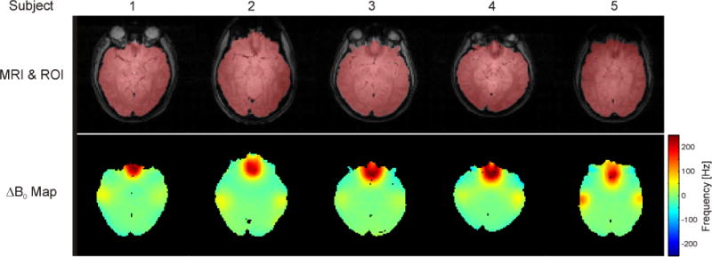
Example B0 distributions in the human brain at 4 Tesla. First row: Axial, anatomical images of five subjects of mixed age, sex and ethnicity. The extracted brain areas are overlaid in red. Second row: Strong and highly localized distortions are primarily observed above the sinuses and the ear cavities (red/yellow foci). Although these B0 distortions show similar patterns in all subjects, considerable inter-subject variability is observed. MRI: magnetic resonance imaging; ROI: region of interest. (Adapted from Juchem et al., MRM 63 (2010)).
Unwanted B0 inhomogeneity throughout the subject of study can affect MRS experiments in a variety of ways, including spectral line broadening, impairment of MRS functions like water suppression that rely on exact frequency definition, and erroneous MRS voxel localization. Their link to B0 inhomogeneity and the experimental consequences they entail are described as follows.
B0 Inhomogeneity and Spectral Linewidth
A series of powerful in vivo MRS methods have been developed to noninvasively retrieve biochemical information from intact tissue. Quantification of in vivo MRS, however, commonly suffers from limited acquisition sensitivity and severe spectral overlap (most 1H brain metabolites, for example, resonate in the 1–4 ppm range). A continuous effort in the MRS community seeks to achieve ever higher B0 magnetic field strength in both humans and animals to improve the attainable acquisition sensitivity and spectral dispersion. Such benefits of higher B0 field are only achieved, however, if certain associated challenges can be overcome. At ultra-high B0 field (≥7 Tesla), the concomitant difficulties are primarily related to aspects of radio-frequency (RF) behavior and B0 inhomogeneity. The shape of B0 inhomogeneity induced by varying magnetic susceptibility conditions is independent of the B0 field strength. Its magnitude, however, is proportional to B0 and, if not corrected properly, the resultant detrimental consequences for MRS are magnified accordingly. In one of the first 1H MRS studies of the human brain at 7 Tesla, Tkac et al. discuss the fundamental importance of B0 shimming for obtaining a net benefit at ultra-high B0 field and, more specifically, the spectroscopic separation of glutamate and glutamine (3). They express the spectral linewidth obtained in vivo as a combination of various factors with contributions from 1) natural linewidth, based on the spin-spin relaxation time T2, plus additional broadening due to 2) microscopic or 3) macroscopic B0 fluctuations throughout the ROI.
The latter B0 variations lead to a spread of Larmor frequencies and a broadening of the resultant peak beyond its natural linewidth. Microscopic line broadening is attributed to B0 effects on a very small spatial scale, as from microscopic heterogeneity of the tissue and/or from accumulation of magnetic iron ions in the substantia nigra in Parkinson’s disease, and, by definition, cannot be corrected for. Note that microscopic B0 fluctuations also involve signal loss due to random and thus irrecoverable diffusion in microscopic field gradients (4). By contrast, line broadening due to macroscopic B0 variations can, in principle, be addressed by B0 correction fields, i.e., B0 shimming. The optimal linewidth under perfect macroscopic B0 shim conditions, however, remains a function of B0 field strength and brain region, i.e. tissue composition (5).
The accurate quantification of 1H MRS brain metabolites depends on the reliable separation of their respective spectroscopic signals. 1H MRS of the human brain, however, inherently suffers from severe spectral overlap of many metabolites including glutamate and glutamine at ~2.4 ppm; creatine, phosphocreatine, γ-aminobutyric acid (GABA), and glutathione (GSH) at ~3 ppm; as well as choline, taurine, phosphoethanolamine and alanine at ~3.2 ppm. Spectral overlap cannot be fully avoided in at near-optimal B0 homogeneity and corresponding linewidths of 10 imulated STEAM MRS, echo time (TE) 10 ms, mixing time (TM) 50 ms, metabolite concentrations from (1,6), no macromolecules, relaxation not considered). The minimization of such overlap and preservation of as much spectroscopic detail as possible is of paramount importance, however, to allow the numerical disentanglement of individual metabolite signals and to maximize the attainable information content (Figure 2A, FWHM 10 Hz). Suboptimal B0 homogeneity, however, broadens spectral lines, reduces MRS signal amplitudes and corrupts otherwise attainable metabolic information (Figure 2B, FWHM 15 Hz). At poor B0 conditions, spectral peaks progressively merge together and eventually become inseparable (Figure 2C, FWHM 20 Hz). While quantification accuracy, for which Cramer-Rao Lower Bounds (CRLB) often serves as maximum confidence measure, might remain sufficient for metabolites containing strong singlets, such as NAA or creatine, the quantification of low-amplitude and/or strongly overlapping signals such as GABA, GSH, or glutamate versus glutamine becomes progressively impossible. The sensitivity of in vivo MRS is inherently limited, and a significant noise floor is the rule rather than the exception. As such, suboptimal B0 conditions directly translate to reduced signal-to-noise ratios (SNR). For simplicity, pure Lorentzian line broadening representing a shortened, mono-exponential transverse decay time T2 has been applied in this example simulation to illustrate the effects of linewidth on spectral overlap and attainable SNR. In reality, such line broadening reflects the underlying Larmor frequencies and, therefore, the background B0 distribution. As such, B0 inhomogeneity not only broadens MRS signals, but also affects their line shape in a complex fashion. Note that the above simulations also neglected the influence of macromolecules. At short TE, macromolecules contribute a significant fraction of the observed signals (7,8). In addition to potential confusion among overlapping (short T2) metabolites, then, the spectroscopic quantification is further impaired at poor B0 conditions when peaks or multiplet structures exhibit linewidths similar to those of macromolecular signals.
FIGURE 2. MRS LINEWIDTH AS A FUNCTION OF B0 HOMOGENEITY.
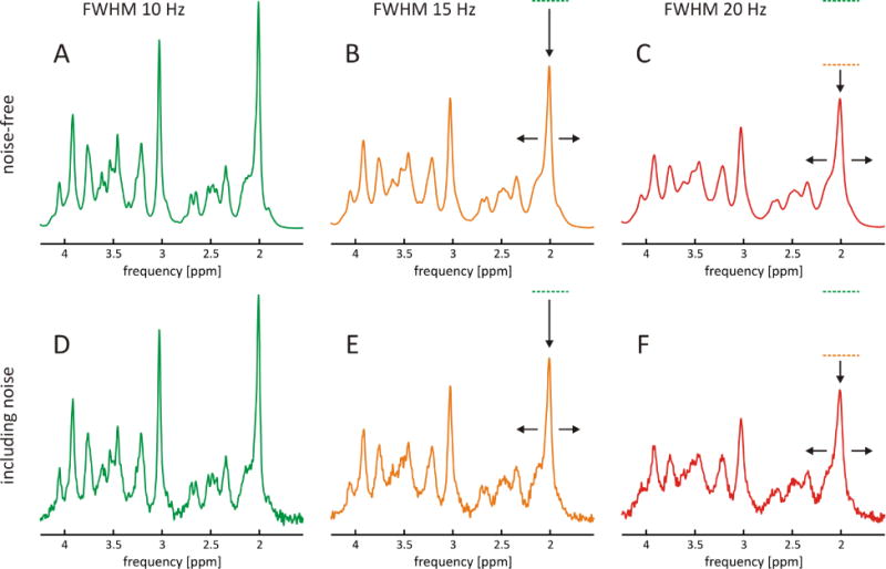
Simulation of spectral appearance of 1H MRS of the human brain at 7 Tesla as a function of spectral linewidth (STEAM, TE 10 ms, TM 50 ms, no macromolecules). A: Excellent B0 field homogeneity results in narrow lines, thereby revealing a wealth of spectroscopic detail and allowing optimal quantification accuracy (green, FWHM 10 Hz). B: Reduced B0 homogeneity results in the broadening of spectral lines, a reduction of MRS signal amplitudes, and a loss of attainable metabolic information (orange, FWHM 15 Hz). C: At poor B0 conditions, spectral peaks merge inseparably (red, FWHM 20 Hz). D–F: In reality, MRS faces a significant noise floor, and imperfections in B0 homogeneity result in losses of signal-to-noise ratio (SNR) and attainable information content. FWHM: full width at half maximum.
Other Impacts of B0 Inhomogeneity on MR Spectroscopy
Chemical shift selective (CHESS) water suppression employs frequency-selective RF pulses to selectively excite and subsequently dephase the water magnetization throughout a chosen volume, thereby minimizing the spectral contribution of water (9). Inhomogeneous B0 conditions result in a distribution of water frequencies instead of a single frequency. This reduces the suppression efficiency if the frequency variation is significant compared to the bandwidth and profile of the selective RF pulses. Note that the sidebands of the RF pulses applied for MRS localization can extend significantly beyond the MRS voxel volume itself. If B0 conditions surrounding the MRS voxel are inhomogeneous, as in the human PFC, reduced suppression efficiency in these areas can thus manifest itself as residual water signal from outside the voxel.
Frequency-selective RF pulses are also commonly employed for spectral editing techniques such as J-difference editing for GABA quantification (10). Here, frequency variations lead to altered editing efficiency and erroneous metabolite quantification. Editing schemes relying on a specific symmetry, such as those applied to minimize macromolecule contributions (11), are potentially affected in a similar fashion.
B0 field inhomogeneity during the application of magnetic field gradients inevitably leads to erroneous spatial assignments that can become a limiting factor for low-bandwidth MRI applications like echo-planar imaging (EPI). The impact of B0 inhomogeneity on localization accuracy, while less critical for MRS, is described here in the context of this review, as the origin of this important B0-induced artifact is universal (Figure 3).
FIGURE 3. GRADIENT ENCODING IN THE PRESENCE OF FIELD INHOMOGENEITY.
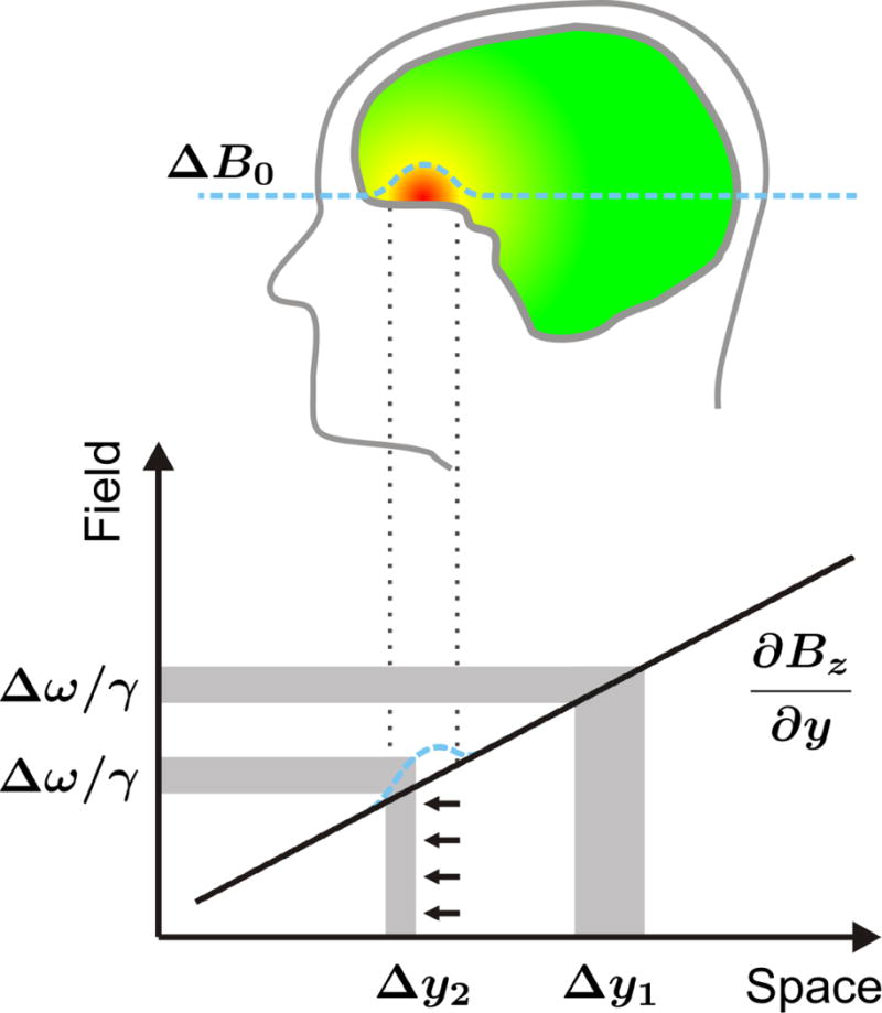
Impact of B0 magnetic field inhomogeneity on spatial encoding with linear magnetic field gradients. Linear field gradients are used in MRS to encode spatial position in frequency. Slice selection for MRS localization is achieved by a tailored combination of a linear field gradient (black line) and a radio-frequency pulse. Slice position and width are given by the combination of gradient strength and RF pulse offset/bandwidth, respectively. Field inhomogeneity (dotted blue) alters the effective gradient field, potentially leading to erroneous slice profile (i.e., thickness) and position.
Linear field gradients are used to encode spatial position in frequency for slice selection and MRS voxel localization by a tailored combination of a linear field gradient (Figure 3, y-gradient dBz/dy, black line) and an RF pulse (upper gray horizontal bar). Slice position and width are determined by the combination of gradient strength and RF pulse offset/bandwidth, respectively (right vertical gray bar, Δy1). Spatial localization with linear magnetic field gradients is based on the assumption that the field distribution throughout the subject is based solely on the applied field gradients. In reality, however, this implicit assumption is regularly violated by apparent background B0 field inhomogeneity (dashed blue line). Such variations in the PFC locally alter the effective gradient field, thereby leading to an erroneous slice profile and position (left vertical gray bar). An RF pulse of unchanged bandwidth (lower horizontal gray bar) thus results in a slice of reduced thickness Δy2. Note that these artifacts are given by the shape and strength of the B0 distortion relative to the applied gradient amplitude and polarity. The effect is therefore highly position-dependent and the opposite artifact, a stretch instead of a squeeze, is observed at the posterior end of the PFC field distortion. The resultant spatial misregistration in MRI can be minimized by post-processing when the shape of the B0 alterations is known (12–16). However, the applicability of such corrections is limited for severe spatial distortions; moreover, complete signal dropout cannot be recovered at all. MRI methods vary in their susceptibility to variations in background B0; unfortunately, the work horses of MRI research and diagnostics, gradient-echo echo-planar imaging (EPI) sequences, tend to be particularly vulnerable to B0 imperfections (17). More importantly for this topic, spatial misregistration for single-voxel MRS cannot be corrected by post-processing.
In general, MR artifacts resulting from imperfect B0 conditions can only be overcome when the underlying physical origin of the problem is removed and the apparent field imperfection is compensated experimentally.
Basics of B0 Shimming
Magnetic fields obey the superposition principle and can be simply summated to shape the effective B0 distribution. B0 shimming describes the process of creating and superimposing a secondary B0 correction field with the purpose of homogenizing a given B0 distribution.
Every analytical, or non-iterative, B0 correction technique relies on exact knowledge of the B0 field distribution to be homogenized. In a first step, the B0 distribution therefore needs to be quantitatively measured (Figure 4, Step I: B0 Field Mapping). The signal of every MRI voxel is a complex value containing both an amplitude and a phase. The acquired phase φ at voxel position r is proportional to the local field variation ΔB0 and the employed echo time TE
with the gyromagnetic ratio γ and γ/(2π) = 42.57 MHz/T for protons. Repetitive MRI at varying TE allows the voxel-specific calculation of ΔB0 based on variations in MRI signal phase and the derivation of volumetric B0 field information (in Tesla or Hertz, assuming 1H) throughout the MRI field of view. At least two echo times are necessary to eliminate the phase offset φ0, but more TE delays are advisable (if experiment time permits) to better define the phase-time behavior and to improve the confidence of the field calculation (18). If MRI are obtained at more than two TE delays (here TE1–4), voxel-specific phase unwraping and linear regression of signal phase versus TE needs to be applied. Alternatively, phase unwrapping can be achieved by spatial techniques since B0 distributions are continuous, and no phase jumps are expected between neighboring positions (19). After the B0 information has been obtained, the ROI for the MRS investigation is defined (Figure 4, Step II: B0 & ROI Calculation). This selection is typically based on the MRS target geometry including the MRS voxel size and position as well as anatomical information derived from the same MRI or other references. Note that all processing should be accompanied by a rigorous quality assessment of both B0 and anatomical information. Erroneous field calculations due to phase errors from blood flow effects or insufficient SNR can lead to apparent frequencies that exceed the true B0 conditions by several orders of magnitude. If not excluded from the analysis, these voxels have the potential to significantly impact the derived B0 correction even if few in number (18). In a third step, theoretical B0 shimming is applied (Figure 4, Step III: Theoretical B0 Field Modeling). This step exploits the available field modeling system to reproduce B0 field inhomogeneity at reversed polarity; the ideal B0 shim field thus exactly resembles the experimental B0 field in every voxel with opposite sign. The summation of this shim field to the background B0 field then fully removes field imperfections, resulting in perfectly homogeneous B0 conditions and a constant field amplitude throughout the ROI (Effective B0, green). Once the best possible shim field has been determined, it is physically generated and applied for the experimental optimization of B0 homogeneity (Figure 4, Step IV: Experimental B0 Shimming & MR Experiment).
FIGURE 4. FLOW DIAGRAM OF B0 SHIMMING.
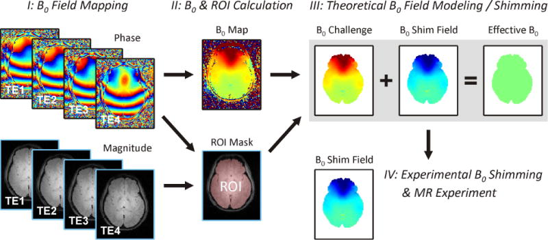
Schematic of B0 shimming procedure. Step I: Mapping of the B0 field distribution, or the inhomogeneity to be minimized, is the first step of every B0 shimming method. This is achieved by repetitive MRI at varying echo time (TE) to capture the effect of B0 on magnetization phase (here, four MRI are applied: TE1–4). Step II: Voxel-specific linear regression of phase versus echo time allows the calculation of a 3D B0 field map (in Tesla or Hertz). Along with anatomical/geometric information derived from the magnitude images, the region-of-interest (ROI, old rose for the brain) can be determined for the target experiment. Step III: Theoretical B0 shimming aims at reproducing the encountered field distribution at reversed polarity with the field modeling system used (e.g., a SH basis set) to erase any spatial B0 variations and to arrive at perfectly homogeneous B0 conditions (Effective B0, green). In reality, B0 shimming methods vary by the way B0 shim fields are produced and, more importantly, their ability to resemble B0 inhomogeneity. Step IV: The best B0 modeling result is then generated experimentally and summed with the ROI. Residual deviations between the B0 inhomogeneity and the best modeling result remain as field imperfections after shimming. ROI: region of interest.
Methods for generating B0 shim fields vary in physical technique and, more importantly for shimming outcome, their ability to accurately model and reproduce B0 distortions. Magnetic field terms observed in vivo can be highly complex, and their practical removal can be complicated by remote positioning, such as deep inside the brain. Residual deviations between B0 inhomogeneity and the best modeling result inevitably remain as field imperfections after the B0 shimming process.
The importance of obtaining adequate magnetic field homogeneity, as in across the entire human brain including its typically problematic areas, has sparked the development of various shimming techniques that are categorized as passive or active as well as static or dynamic based on the way the correction fields are generated and applied, respectively.
Passive Shimming
Magnetic field shapes induced by varying magnetic susceptibility conditions are responsible for the existence of the largest part of the B0 distortions in the human brain, but the very same effect can also be applied to their correction. Magnetically susceptible materials alter the surrounding magnetic field distribution when placed inside a magnet, thus providing a handle on the distribution in neighboring objects. Passive shimming exploits this effect through strategic placement of magnetically susceptible materials within the scanner bore, thereby manipulating and homogenizing the magnetic field over parts of the subject as needed. Materials used in passive shimming range from diamagnetic intraoral shims for the minimization of field artifacts in the human prefrontal cortex (20–22) to external dia- and paramagnetic passive shims for whole-brain shimming in the mouse (23,24). Matching the magnetic properties of a human head holder (with pyrolytic graphite foam) to the diamagnetic properties of the head/neck that it hosts can also be understood as form of passive shimming (25). Passive shimming with ferromagnetic substances provides an inexpensive means of efficiently producing very strong magnetic fields. Ferromagnetic materials have also been applied in a subject-specific fashion (26,27).
Since the early days of MR, the B0 distribution of the MR scanner itself is improved by placement of small pieces of iron or steel (“shims”) to strategic positions; as such, the term “shimming” now applied to describe any type B0 homogenization technique, is rooted in the passive variant. Notably, optimized numerical methods have been recently proposed to efficiently calculate the B0 fields induced by arbitrary magnetic susceptibility distributions, thereby providing a versatile tool for understanding the B0 effects induced in the human body and their possible correction with passive shimming (28,29). Passive shimming is marked by ease of field generation via simple placement of the assemblies to be polarized inside the scanner field. The creation and adjustment of such passive shim assemblies is, however, cumbersome. More importantly, passive shimming generally lacks the flexibility to accommodate experiment-specific conditions and varying shim requirements due to differences in subject anatomy (compare, for example, the five cases in Figure 1), subject placement or altered susceptibility distributions (e.g., due to the nasal congestion of a subject with a cold). While the benefits of passive shimming for specific MRS applications have been demonstrated, its practical shortcomings have prevented it from becoming the common method of choice.
Active Shimming with Spherical Harmonic Shapes
Active shimming refers to B0 homogenization with correction fields produced by electrical coils. The standard approach to minimizing magnetic field variations for MRS with active shimming is to superimpose magnetic fields with a spatial variation governed by spherical harmonic (SH) functions (30,31). The magnetic field in free space obeys the Laplace equation, and solutions thereof can be expressed as SH expansions. While the space is arguably no longer empty when objects are studied with MRS, the SH framework has prevailed likely due to its experimental practicality and ubiquity in the fields of chemistry and physics. SH functions are orthogonal and organized in orders N with 2N+1 terms per order (Figure 5). The single zero-order shape is a general offset (not shown), and the three first-order terms describe linear field gradients identical to those applied for spatial encoding. Higher orders contribute shapes with higher order symmetry and multiplicity (Figure 5, compare 1st order: X, 2nd order: X2-Y2 and XY, 3rd order: X3, 4th order: X4) and therefore enable the modeling of increasingly complex target field shapes. In general, the higher the maximum SH order applied for B0 shimming, the more likely it is that it will resemble the spatial features of given B0 distortions and thereby allow their subsequent compensation by B0 shimming. In other words, the number of basis functions available for modeling the field distortion determines the flexibility of magnetic field shaping; the quality of the expected shim outcome is thus improved if higher orders are included (32).
FIGURE 5. SPHERICAL HARMONIC FUNCTIONS.
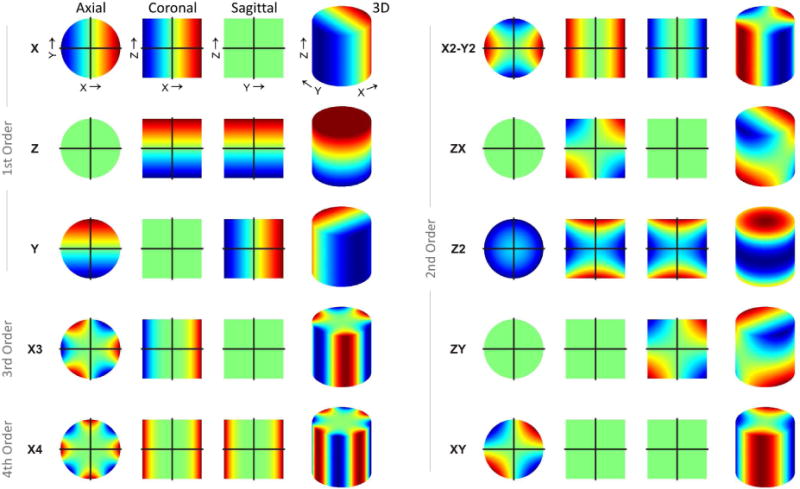
Selection of 1st through 4th order spherical harmonic (SH) shapes. Spherical harmonic functions are organized in orders N with 2N+1 terms per order. The single zero order shape represents a global offset (not shown) and the three first-order terms describe linear field gradients identical to those applied for spatial encoding. Higher orders contribute shapes with higher-order symmetry and multiplicity (compare 3rd: X3, 4th: X4: to 1st: X, 2nd: X2-Y2 and XY) and can therefore model progressively advanced target field shapes. In general, the higher the maximum SH order applied in B0 shimming and the larger the number of shapes included, the more likely is the successful modeling of B0 distortions and their subsequent compensation by B0 shimming.
The B0 field generated by electrical charges flowing through a conducting wire is described by Biot-Savart’s law. Shaping the wire pattern allows a handle on the current distribution and the magnetic field shape that is created. This principle is exploited to produce individual SH shapes by dedicated, current-driven wire patterns one for each term and a set of SH coils is nested inside the scanner bore to form a shim system that generates B0 correction fields over the subject. In practice, SH shim systems are limited to low-order terms due to space and cost restrictions. Most human MR systems are equipped with shim coils capable of generating SH fields up to the second or third order. SH shimming is a robust and flexible method that can be fully automated to provide objective, user-independent magnetic field homogeneity (33–36).
The orthogonality of the SH basis functions allows the individual adjustment of SH shim terms under the assumption that the fields generated by the SH wire patterns are indeed pure and truly independent. In reality, however, most SH coils also produce other, unwanted terms along with the primary shape that determines the coil’s name. These cross-terms are not necessarily a problem as long as they can be modeled with B0 shapes from other available shim coils and subsequently considered in the computation of the applicable set of B0 shim currents (37).
Figure 6 shows an example analysis of SH field modeling and theoretical B0 shimming for single voxel MRS in the human prefrontal cortex at 4T (ROI size 4×4×4 cm3). Magnetic susceptibility boundaries near the frontal bone result in strong and complex B0 inhomogeneities that can severely disrupt and potentially ruin MRS investigations in the PFC. The inclusion of higher-order SH functions and shapes facilitates progressively better resemblance of B0 distortions and improved B0 shim outcome, reflected in reduced standard deviation (SD) of the residual field distribution.
FIGURE 6. SINGLE VOXEL SHIMMING: 0 TO 4TH ORDER.
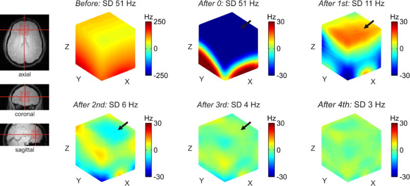
Spherical harmonic field modeling and B0 shimming for single voxel MRS in the human prefrontal cortex at 4T as a function of SH order (cube size 4×4×4 cm3). Magnetic susceptibility transitions in the frontal head result in strong and complex-shaped B0 inhomogeneities that have the potential to render MRS investigations in the PFC useless. The inclusion of higher-order SH functions and shapes allows progressively better resemblance of the B0 distortions and improved B0 shim outcomes, corresponding to reduced standard deviation (SD) of the residual field distribution. Note that the residual field imperfection is a function of the employed set of basis functions and can vary regionally in both shape and polarity with the inclusion of additional SH orders (arrows, 1st order: strongly positive, 2nd order: intermediate negative, 3rd order: slightly positive).
B0 shimming aims to improve the overall B0 homogeneity of the ROI. Numerically, this is typically achieved by least-squares minimization of the sum of the original B0 challenge and the B0 shim field to be applied. With this approach, the residual field deviations of every voxel are combined quadratically and therefore irrespectively of sign. The synthesized field with the smallest overall deviation in terms of this single metric is considered the best fit. If the B0 challenge can be perfectly resembled by the shim system, this quality measure becomes zero, and perfect B0 homogeneity is achieved. In most cases, the applied basis set is not capable of perfectly resembling all field distortion. While there is only one perfectly homogeneous B0 scenario, imperfect solutions are not unique, but to some degree rely on the chosen B0 homogeneity metric. Note that the residual field imperfection depends on the employed set of basis functions and thus can vary in both shape and polarity with the inclusion of additional SH orders (Figure 6, arrows). While the overall B0 homogeneity is improved, regional B0 homogeneity might be compromised and residual distortions can potentially even reverse polarity. This might appear counterintuitive at first but can be well understood given a particular pattern of B0 inhomogeneity, the available B0 shim system, and the characteristics of the numerical optimization routine (i.e., the cost-function).
Tkac et al. estimate the resolution limit for 7-Tesla 1H MRS of adult human brain to correspond with a linewidth of 9 Hz for total creatine, or the combination of creatine and phosphocreatine (3). This finding is consistent with our experience and can even be obtained in the PFC when B0 shimming is optimal (Figure 6A, 7 Tesla, STEAM, TE 10 ms, TM 50 ms, 8 cc, FWHM of tCr 8.8 ± 0.2 Hz, FWHM of NAA 7.3 ± 0.2 Hz). Excellent B0 homogeneity is the basis for reliable quantification of the overall neurochemical profile (38) and, moreover, the separation of glutamate and glutamine at 7 Tesla. At this spectral quality, even the multiplet structure of the glutamate C4 protons at 2.35 ppm becomes clearly visible in both the experimental spectrum and the scaled glutamate basis function.
Fast Automatic Shimming Technique by Mapping Along Projections (FASTMAP)
Full 3D mapping of B0 field conditions can be time-consuming. Instead, the fast automatic shimming technique by mapping along projections (FASTMAP) samples the B0 field distributions to be homogenized along six exemplary, orthogonal column projections only (Figure 7, cube size 14 mm, projection length 19.8 mm). Basic linear algebra is applied to unambiguously derive the unique solutions for the apparent first and second SH order field imperfections from this small set of measured polynomial B0 terms. Given the available B0 shim system, the apparent B0 inhomogeneity is then converted to the corresponding correction field. Note that the key of the FASTMAP approach lies in the efficient determination of 3D B0 conditions with a sparse sampling approach. The subsequent determination of the B0 shim field is standard.
FIGURE 7. SELECTED 1H MRS OF THE HUMAN PFC AT 7 TESLA.
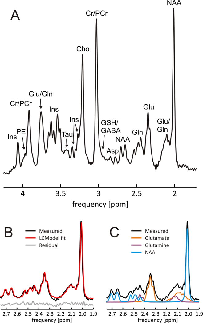
In vivo single-voxel 1H MRS of the human prefrontal cortex at 7 Tesla (STEAM, TE 10 ms, TM 50 ms). Third SH order B0 shimming allows excellent line width (FWHM of NAA 7.3 ± 0.2 Hz, Cr/PCr 8.8 ± 0.2 Hz). B/C: Clear separation of glutamate and glutamine and resultant high-accuracy LCModel decomposition of metabolic component. At this spectral quality, even the multiplet structure of the glutamate C4 protons at 2.35 ppm can be appreciated in both the experimental spectrum and the glutamate basis function. Ins: myo-ionositol, PE: phosphorylethanolamine, Cr: creatine; PCr: phosphocreatine; Glu: glutamate; Gln: glutamine; Tau: taurine; Cho: choline; GSH: glutathione; GABA: γ-aminobutyric acid; Asp: aspartate; NAA: N-acetyl aspartate.
The sampling of selected column projections assumes smooth and well-behaved B0 field conditions. Obviously, very localized distortions that are not captured by one of the column projections are not considered. If applied to reasonably small volumes for single-voxel MRS, however, such cases are rare. Full 3D field mapping does provide a more detailed and complete picture of the apparent B0 conditions of such a specialized scenario. In practical reality, the limited capability of second-order SH field modeling to resemble such extreme B0 scenarios is more likely to be the limiting factor than the sparsity of the employed column projections.
FASTMAP is an elegant, analytical method that provides a versatile tool for second SH order B0 homogenization in cubic volumes typical for single-voxel MRS investigations. As such, FASTMAP (and its derivatives (39,40)) has become the method of choice in many laboratories due to significantly reduced acquisition times compared to B0 shimming methods that are based on full 3D MRI. An optimized FASTMAP implementation at 7 Tesla has been recently shown to allow localized B0 shimming at low specific absorption rate (SAR), i.e. RF power deposition, in less than 1 minute (41).
The B0 shim ROI typically resembles the ROI of the MR investigation, but can differ as long as the characteristics of the B0 distribution to be homogenized are properly captured. FASTMAP operates on cubic ROIs and is typically chosen to provide B0 shimming for MRS in single voxels. A moderate extension of the B0 shim ROI beyond the geometry targeted by the MR investigation is sometimes useful if very small ROIs are considered to improve the robustness of the B0 shim computation. This approach should be used with care, however, as it rests on the assumption that the B0 distribution in the vicinity of the original ROI resembles the shapes encountered within the original ROI. A moderate ROI extension can therefore be applied in parts of the brain where B0 conditions can be expected to change slowly, but must be avoided in areas of severe local B0 gradients or at the brain surface if no further quality and selection measures are applied. The homogenization of B0 conditions in slabs or complex-shaped volumes such as the entire human brain requires 3-dimensional B0 mapping methods along with algorithms to select the desired ROI based on geometric conditions, e.g. slab position and thickness, and/or anatomical aspects, e.g. brain segmentation.
Dynamic Shimming with Spherical Harmonic Shapes
High-quality B0 homogeneity can be readily achieved with low SH order B0 shimming in small areas considered for single-voxel MRS. B0 shimming with SH shapes is also capable of removing large part of the B0 imperfections encountered throughout the entire human brain (Figure 9). As expected, the inclusion of higher order shapes provides progressively better results and a nearly perfect elimination of the widespread, shallow terms (32). Complex and localized magnetic field distortions, such as those observed in the human PFC or the temporal lobes, are beyond the modeling capability of current static SH shimming. They can be somewhat reduced by the low-order SH fields to which current technology is limited, but they cannot be removed. As such, limited B0 homogeneity throughout the human brain has been a long-standing problem.
FIGURE 9. STATIC SH WHOLE BRAIN SHIMMING.
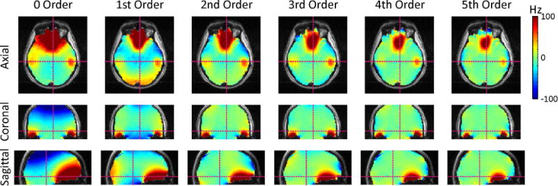
Whole-brain B0 homogenization as a function of SH shim order (here: 4 Tesla). SH shimming is capable of removing a large part of the B0 imperfections observed in the human brain. The inclusion of higher orders allows progressively better results and a nearly perfect elimination of the widespread, shallow terms. The localized B0 terms observed in the temporal lobes and the prefrontal cortex are beyond the modeling capability of available SH shimming and can only be reduced, but not removed.
Global B0 shimming aims to optimize the B0 conditions over the entire object under investigation at once (Figure 10A, 1D example, gray dotted range). The best B0 shim field is then applied experimentally and remains constant, or static, throughout the MR investigation. If the MR sequence employs a serial scheme in which different subvolumes of the considered object are sampled sequentially, as in interleaved multi-voxel MRS or multi-slice MRI, a series of B0 shim conditions can be optimized for every such subvolume separately (Figure 10B). The B0 shim condition tailored to an individual subvolume is then applied immediately before MR signal is measured and updated to the next B0 shim setting and subvolume immediately after. The adjustment of subunit-specific shim settings with this dynamic shim approach allows the improved optimization of magnetic field homogeneity over the original, larger volume based on the individual improvements in the constituent subvolumes.
FIGURE 10. BASIC CONCEPT OF DYNAMIC SHIMMING.
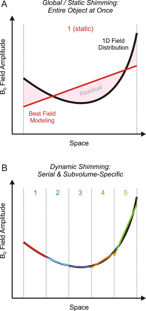
Illustration of dynamic B0 shimming. (A) Global B0 shimming aims to compensate the field distortion (black parabolic) throughout the entire object at once (gray dotted). If the assumed linear field modeling system (red), however, is not capable of resembling the distortion, the difference (pink) will inevitably remain as residual B0 inhomogeneities after the shimming process. (B) Complex field shapes can be described by simpler terms when considered regionally over smaller volumes. This characteristic is comparable to the approximation of a 1-dimensional, complex mathematical function through straight lines (similar to the computation of a difference quotient) and becomes progressively more accurate as the considered functional range becomes more localized. Dynamic shimming capitalizes on this principle by breaking down a large volume such as the human brain into subunits. The adjustment of subunit-specific shim settings (1–5, colored) then allows the improved optimization of magnetic field homogeneity over the original, larger volume based on the individual improvements in the constituent subvolumes. Note that every active B0 shimming method is more powerful when applied in a dynamic fashion, irrespective of the employed basis set.
After the introduction of dynamic shimming for multi-slice MRI with linear gradients (42,43), the benefits of including second-order SH terms (44,45) and third-order SH terms (37) have been demonstrated. Besides the application of dynamic shimming to MRI, multi-voxel MRS with dynamically updated, voxel-specific shim settings has been shown to allow multi-fold efficiency gains (46,47). In the same vein, multi-slice MR spectroscopic imaging (MRSI) with dynamically updated zero through third SH order B0 (and B1+) shimming has been demonstrated in the human brain at 7 Tesla (48).
In principle, dynamic shimming using first SH order shapes can be achieved on every MRI scanner with the system’s amplifier electronics and built-in gradient coils. B0 shim amplifiers, however, are generally designed to provide constant current output and are not capable to rapidly alter currents as need for dynamic shimming. As such, second and higher SH order dynamic shimming requires dedicated amplifier electronics for fast updating of individual B0 shim conditions during the experiment (37,45). The rapid field switching with coils fitted to the scanner bore induces eddy currents in the magnet’s cold conducting structures that result in a multitude of artificial field terms throughout the bore. The quantitative spatial and temporal characterization of all of these field terms is necessary for the identification of significant components (37,49,50). Their experimental minimization by shim pre-emphasis and B0 compensation is essential for successful higher SH order dynamic shimming (37,45,49). Note that standard B0 shim amplifiers are neither capable of rapid current switching nor do they allow shim preemphasis, and higher SH order dynamic shimming is therefore generally not possible on standard clinical MRI scanners. Dynamic shimming is inherently more powerful than static (global) shimming for any given shim system. The increased effort and complexity of its experimental realization with the inclusion of additional SH orders, however, is expected to eventually outweigh its diminishing marginal returns (37).
Real-Time Shimming with Spherical Harmonic Shapes
Correction fields for dynamic shimming as discussed above are updated for each period spent by the MR sequence on its individual subvolumes, typically once per repetition time. In other words, the term “dynamic” shimming describes the fast, serial adjustment of otherwise constant shim fields over modular subvolumes constituting the overall ROI. Similar to static B0 shimming, the B0 distributions is mapped ahead of time and shim corrections are derived for the subsequent MR scan assuming unchanged B0 conditions. As such, dynamic shimming does not account for temporal field variations as they are observed in the human brain e.g. due to oscillatory changes in the body’s susceptibility distribution during breathing. A preparation scan for full spatio-temporal mapping of the B0 conditions in the brain over the subject’s respiratory cycle has been the basis for a continuous adaptation of B0 correction, so-called real-time shimming, for the compensation of such temporally varying field alterations (51). The term “real-time” shimming has also been used to describe the periodic interleaving of MR sequences with B0 measurements and subsequent dynamic updating of B0 field conditions, such as once per repetition time. This technique is fast compared with the overall scan duration (hence, “real-time”) and allows accounting for changing B0 conditions that result from subject movement (52–54). Continuous monitoring and instantaneous correction of the gradient and shim coil performance with a B0 field camera assures optimal system stability (55,56) and is expected to set the stage for development of truly real-time B0 shimming in the future.
Static and Dynamic Multi-Coil Shimming
The experimentally available low-order SH terms allow for the modeling of and thus compensation for large-scale and shallow magnetic field components. The complex field terms generated by the sinuses in the human PFC and by the auditory cavities in the temporal lobes cannot, however, be corrected adequately (Figure 11D, 7 Tesla (37)). While significant improvements in B0 magnetic field homogeneity have been demonstrated with dynamic shimming for most parts of the human brain, even dynamic shimming with all zero-through third-order SH terms is not capable of completely homogenizing the entire organ (Figure 11F). Note the negative light blue ring around the PFC field focus and the additional small field alterations induced in other parts of the brain. Similar to the example of single-voxel B0 shimming with varying SH order functions (Figure 6), the field modeling is not capable of fully compensating for the distortion. As such, the shim optimization balances field variations in different locations to improve its overall homogeneity. More specifically, the dominant field focus in the PFC is reduced at the expense of allowing some B0 imperfection in other parts of the brain.
FIGURE 11. COMPARISON OF DIFFERENT B0 SHIMMING STRATEGIES.
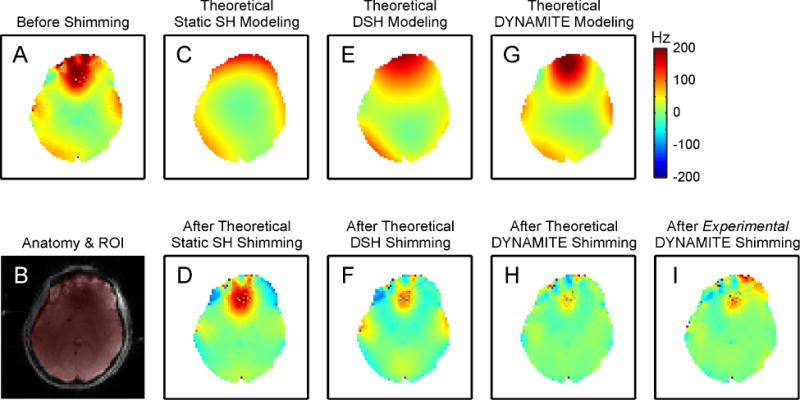
Magnetic field modeling characteristics of different B0 shimming strategies (first row) and their performance for shimming of the human brain at 7 Tesla (second row, except B). The zero through third order SH functions allow the synthesis and removal of shallow magnetic field components (C,E), but significant imperfections remain throughout the brain or were even induced (D,F). DYNAMITE B0 shimming is capable of generating a magnetic field distribution that closely resembles the original distortion over the entire slice including the strong and localized focus in the PFC (G). Correspondingly, DYNAMITE B0 shimming removes the largest part of the field inhomogeneity as predicted theoretically (H) and shown experimentally (I). SH: spherical harmonic; DSH: Dynamic spherical harmonic; DYNAMITE: dynamic multi-coil technique; ROI: region of interest. (Adapted from Juchem et al., JMR 212 (2011)).
SH functions are only one of the possible basis sets for the description and synthesis of magnetic fields. However, despite some specialized, non-SH shim approaches for the human prefrontal cortex on the basis of localized, intra-oral coils (57) or a specifically tailored set of external coils (18), the orthogonality of the basis shapes has been accepted by the MR community as an essential prerequisite for magnetic field modeling and shimming based on early reports (31). We demonstrated recently that a set of generic, localized coils can be converted to a powerful magnetic field modeling system when each of the electrical coils is driven individually (58). In other words, the orthogonality of the basis functions is not a requirement for successful magnetic field modeling. This multi-coil (MC) concept allows for the synthesis of simple and complex magnetic fields in a flexible and accurate fashion via the superposition of generic non-orthogonal basis fields. B0 shimming with static and especially dynamic (DYNAmic Multi-CoIl Technique or DYNAMITE) MC techniques have been shown to outperform currently available SH shimming procedures in the mouse brain (59,60), the rat brain (61) and the human brain (17,62).
In the human brain, DYNAMITE B0 shimming is capable of generating a magnetic field distribution that more closely resembles the original distortion over the entire slice including the strong and localized field focus in the PFC (Figure 11G). Correspondingly, DYNAMITE shimming removes the largest part of the magnetic field inhomogeneity as predicted theoretically (Figure 11H) and shown experimentally (Figure 11I). Note that neither B0 eddy currents nor cross-talk between individual MC elements has been significant with DYNAMITE and, therefore, no compensation was necessary.
Static MC and DYNAMITE B0 shimming with dedicated coil systems is well-established and has the potential to replace SH-based B0 shimming due to improved shim performance and field generation efficiency (60). The application of constant currents to the individual elements of RF phased arrays and the use of the RF coil system for MC B0 shimming promises efficient usage of limited bore space (63,64). MC and RF coil systems, however, do not share all design principles and B0 shim performance of merged MC-RF systems equivalent to dedicated MC designs is yet to be shown. To date, MC-based B0 shimming has not been applied to MRS. Its use is conceptually identical to previous applications for MRI and is currently pursued in our laboratory. Conventional SH shimming provides high-level B0 homogeneity in most parts of the brain, especially when applied locally for single-voxel MRS, and consequently no further improvements are anticipated from MC-based (or any other) B0 shimming techniques. Benefits of MC-based B0 shimming are expected, however, for applications such as multi-voxel MRS or multi-slice MRSI that span larger parts of the brain potentially including areas of severe B0 disturbances.
The B0 field focus in the PFC is strongest at its ventral end and falls off towards the central/dorsal brain (compare figure 9). Adequate B0 homogeneity can therefore be more easily achieved in the central PFC. The presentation of those slices, thereby excluding the ventral PFC, might suggest an overall B0 shim performance that, in fact, is possible only in the less critical parts of the brain. A more complete impression can be achieved, for instance, with a 3D representation focusing on the brain regions critical for B0 shimming (Figure 12, Static third SH order (A) and DYNAMITE (B) B0 shimming of the human brain at 7 Tesla). In this example, both methods remove the largest part of the widespread shallow B0 components throughout the brain. Following SH shimming, significant B0 field imperfections remain, however, in the PFC and the temporal lobes where B0 distortions are localized and complex. The combination of improved B0 field modeling capability and dynamic shimming with DYNAMITE B0 shimming accomplishes largely homogeneous B0 conditions throughout the brain, including challenging areas such as the PFC and the temporal lobes.
FIGURE 12. DYNAMITE VS. SH SHIMMING OF THE HUMAN BRAIN.
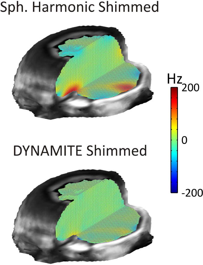
Comparison of DYNAMITE and static third SH order modeling for B0 shimming of the human brain at 7 Tesla. Both methods remove the largest part of shallow B0 components throughout the brain. Significant B0 field imperfections remain with SH shimming, however, in the PFC and the temporal lobes where B0 imperfections are localized and complex. The combination of improved B0 field modeling capability and dynamic shimming with DYNAMITE B0 shimming allows largely homogeneous B0 conditions throughout the brain including challenging areas in the PFC and the temporal lobes. SH: spherical harmonic, DYNAMITE: dynamic multi-coil technique.
Summary and Outlook - Which Shimming Method is Best for Me?
The existence of limited B0 homogeneity and the consequent demand to cope with it secondary to an intended MR investigation can be vexing. Given the experimental burden of B0 shimming and the concomitant time requirement, there is a constant temptation to compromise on this step. Magnetic field inhomogeneity, however, can lead to image distortion and signal loss in MRI, and degraded spectral resolution, reduced sensitivity, and additional varied artifacts in MRS. All such effects can severely limit or obviate the validity of the corresponding investigations. Adequate B0 homogeneity is therefore a necessity, not a choice.
Optimal B0 shimming relies on the accurate knowledge of the employed basis shapes and amplitudes and the precise synthesis of the optimal B0 shim field determined theoretically. The comprehensive, high-quality calibration of any B0 shimming method is therefore of paramount importance, as incomplete knowledge or erroneous characterization of the shim system result in regular suboptimal B0 shim performance. The B0 shim outcome is similarly impaired if the strength of required shim field exceeds the capacity of the available coil system and amplifier electronics. In such a case, the shapes can be reproduced with the available B0 shim system, but the dynamic range appears insufficient for their compensation. The benefits of combined passive and active SH B0 shimming have been presented for special cases in which the dynamic range of active shimming alone has not been sufficient (27,65). In general, however, insufficient dynamic range of the B0 shim system inevitably reduces the attainable B0 homogeneity.
A variety of shimming methods has been developed for the practical realization of B0 correction fields. The B0 distribution can be altered passively through placement of magnetic materials or actively by driving electrical coils. Active shimming is achieved by combining a set of basis functions, either orthogonal (e.g., spherical harmonic) or non-orthogonal (e.g., multi-coil). Dynamic B0 shimming is inherently more powerful than static shimming irrespective of the employed basis set. To date, however, no trivial and effortless B0 shimming method exists that provides perfect B0 homogeneity for all conditions. Shimming techniques vary significantly in their performance as well as the required effort, methodological complexity and financial burden of their implementation. MR laboratories therefore have to decide what shimming capabilities to make available, and individuals have to select among the resultant range of methods to employ. The best B0 shimming method depends on the MR application for which it is used and choosing is not a trivial task, as multiple factors ranging from the species- and region-dependency of apparent magnetic field distortions and the necessary level of field homogeneity are to be considered. For instance, adequate magnetic field homogeneity throughout the entire human brain is required for true 3D whole-brain applications, necessitating robust global static shimming. By contrast, excellent B0 homogeneity can typically be achieved in small volumes for single voxel MRS with second-order SH functions (3). In addition, magnetic field homogenization of axial slices in dorsal brain regions does not face the challenging B0 distortions characteristic of ventral slices, and significantly simpler approaches can thus be sufficient. Finally, some MR applications are less susceptible to magnetic field imperfections than others, and additional insignificant gains in field homogeneity might not warrant the required additional investment of resources, especially in clinical MRS studies that are inherently time constrained. As a result, the successful MR researcher requires not only broad familiarity with the execution of various B0 shimming methods but also a deep comprehension of the underlying theories and characteristics that render them the best tools for a particular job.
FIGURE 8. FASTMAP.
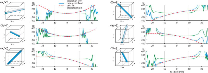
FASTMAP is an efficient analytical method for second SH order B0 homogenization in the cubic volumes typical of single-voxel MRS investigations. The B0 field distributions of the selected volume is measured along six exemplary column projections (left: blue columns, right: blue solid curves) and decomposed into linear first SH order and parabolic second SH order shapes (vertical gray bars). The solution of the resultant set of linear equations is then applied to convert the B0 curves to first and second SH order B0 shim requirements (red dashed) and to predict the achievable B0 homogeneity (green solid).
Acknowledgments
The contribution of Hetty Prinsen, PhD, in the acquisition of the 1H MR spectrum of Figure 7 and the careful proof-reading of the manuscript by Kelley Swanberg, MSc, are acknowledged. This work was supported by the National Multiple Sclerosis Society (NMSS RG 4319), the Nancy Davis Foundation, and NIH grants UL1 TR000142, R01NS062885 and P30-NS052519.
Footnotes
Publisher's Disclaimer: This is a PDF file of an unedited manuscript that has been accepted for publication. As a service to our customers we are providing this early version of the manuscript. The manuscript will undergo copyediting, typesetting, and review of the resulting proof before it is published in its final citable form. Please note that during the production process errors may be discovered which could affect the content, and all legal disclaimers that apply to the journal pertain.
References
- 1.Govindaraju V, Young K, Maudsley AA. Proton NMR chemical shifts and coupling constants for brain metabolites. NMR Biomed. 2000;13(3):129–153. doi: 10.1002/1099-1492(200005)13:3<129::aid-nbm619>3.0.co;2-v. [DOI] [PubMed] [Google Scholar]
- 2.Schenck JF. The role of magnetic susceptibility in magnetic resonance imaging: MRI magnetic compatibility of the first and second kinds. Med Phys. 1996;23(6):815–850. doi: 10.1118/1.597854. [DOI] [PubMed] [Google Scholar]
- 3.Tkac I, Andersen P, Adriany G, Merkle H, Ugurbil K, Gruetter R. In vivo 1H NMR spectroscopy of the human brain at 7 T. Magn Reson Med. 2001;46(3):451–456. doi: 10.1002/mrm.1213. [DOI] [PubMed] [Google Scholar]
- 4.Michaeli S, Garwood M, Zhu XH, DelaBarre L, Andersen P, Adriany G, Merkle H, Ugurbil K, Chen W. Proton T2 relaxation study of water, N-acetylaspartate, and creatine in human brain using Hahn and Carr-Purcell spin echoes at 4T and 7T. Magn Reson Med. 2002;47(4):629–633. doi: 10.1002/mrm.10135. [DOI] [PubMed] [Google Scholar]
- 5.Emir UE, Auerbach EJ, Van De Moortele PF, Marjanska M, Ugurbil K, Terpstra M, Tkac I, Oz G. Regional neurochemical profiles in the human brain measured by (1)H MRS at 7 T using local B(1) shimming. NMR Biomed. 2012;25(1):152–160. doi: 10.1002/nbm.1727. [DOI] [PMC free article] [PubMed] [Google Scholar]
- 6.de Graaf RA. Vivo NMR Spectroscopy: Principles and Techniques. London: John Wiley and Sons; 2008. [Google Scholar]
- 7.Behar KL, Rothman DL, Spencer DD, Petroff OA. Analysis of macromolecule resonances in 1H NMR spectra of human brain. Magn Reson Med. 1994;32(3):294–302. doi: 10.1002/mrm.1910320304. [DOI] [PubMed] [Google Scholar]
- 8.Cudalbu C, Mlynarik V, Gruetter R. Handling macromolecule signals in the quantification of the neurochemical profile. J Alzheimers Dis. 2012;31(Suppl 3):S101–115. doi: 10.3233/JAD-2012-120100. [DOI] [PubMed] [Google Scholar]
- 9.Haase A, Frahm J, Hanicke W, Matthaei D. 1H NMR chemical shift selective (CHESS) imaging. Phys Med Biol. 1985;30(4):341–344. doi: 10.1088/0031-9155/30/4/008. [DOI] [PubMed] [Google Scholar]
- 10.Rothman DL, Petroff OA, Behar KL, Mattson RH. Localized 1H NMR measurements of gamma-aminobutyric acid in human brain in vivo. Proc Natl Acad Sci U S A. 1993;90(12):5662–5666. doi: 10.1073/pnas.90.12.5662. [DOI] [PMC free article] [PubMed] [Google Scholar]
- 11.Henry PG, Dautry C, Hantraye P, Bloch G. Brain GABA editing without macromolecule contamination. Magn Reson Med. 2001;45(3):517–520. doi: 10.1002/1522-2594(200103)45:3<517::aid-mrm1068>3.0.co;2-6. [DOI] [PubMed] [Google Scholar]
- 12.Jezzard P. Correction of geometric distortion in fMRI data. Neuroimage. 2012;62(2):648–651. doi: 10.1016/j.neuroimage.2011.09.010. [DOI] [PubMed] [Google Scholar]
- 13.Fernandez-Seara MA, Wehrli FW. Postprocessing technique to correct for background gradients in image-based R*(2) measurements. Magn Reson Med. 2000;44(3):358–366. doi: 10.1002/1522-2594(200009)44:3<358::aid-mrm3>3.0.co;2-i. [DOI] [PubMed] [Google Scholar]
- 14.Cusack R, Brett M, Osswald K. An evaluation of the use of magnetic field maps to undistort echo-planar images. Neuroimage. 2003;18(1):127–142. doi: 10.1006/nimg.2002.1281. [DOI] [PubMed] [Google Scholar]
- 15.Jezzard P, Balaban RS. Correction for geometric distortion in echo planar images from B0 field variations. Magn Reson Med. 1995;34(1):65–73. doi: 10.1002/mrm.1910340111. [DOI] [PubMed] [Google Scholar]
- 16.Weiskopf N, Klose U, Birbaumer N, Mathiak K. Single-shot compensation of image distortions and BOLD contrast optimization using multi-echo EPI for real-time fMRI. Neuroimage. 2005;24(4):1068–1079. doi: 10.1016/j.neuroimage.2004.10.012. [DOI] [PubMed] [Google Scholar]
- 17.Juchem C, Umesh Rudrapatna S, Nixon TW, de Graaf RA. Dynamic multi-coil technique (DYNAMITE) shimming for echo-planar imaging of the human brain at 7 Tesla. Neuroimage. 2015;105:462–472. doi: 10.1016/j.neuroimage.2014.11.011. [DOI] [PMC free article] [PubMed] [Google Scholar]
- 18.Juchem C, Nixon TW, McIntyre S, Rothman DL, de Graaf RA. Magnetic field homogenization of the human prefrontal cortex with a set of localized electrical coils. Magn Reson Med. 2010;63(1):171–180. doi: 10.1002/mrm.22164. [DOI] [PMC free article] [PubMed] [Google Scholar]
- 19.Cusack R, Papadakis N. New robust 3-D phase unwrapping algorithms: application to magnetic field mapping and undistorting echoplanar images. Neuroimage. 2002;16(3 Pt 1):754–764. doi: 10.1006/nimg.2002.1092. [DOI] [PubMed] [Google Scholar]
- 20.Wilson JL, Jenkinson M, Jezzard P. Optimization of static field homogeneity in human brain using diamagnetic passive shims. Magn Reson Med. 2002;48(5):906–914. doi: 10.1002/mrm.10298. [DOI] [PubMed] [Google Scholar]
- 21.Wilson JL, Jezzard P. Utilization of an intra-oral diamagnetic passive shim in functional MRI of the inferior frontal cortex. Magn Reson Med. 2003;50(5):1089–1094. doi: 10.1002/mrm.10626. [DOI] [PubMed] [Google Scholar]
- 22.Cusack R, Russell B, Cox SM, De Panfilis C, Schwarzbauer C, Ansorge R. An evaluation of the use of passive shimming to improve frontal sensitivity in fMRI. Neuroimage. 2005;24(1):82–91. doi: 10.1016/j.neuroimage.2004.08.029. [DOI] [PubMed] [Google Scholar]
- 23.Koch KM, Brown PB, Rothman DL, de Graaf RA. Sample-specific diamagnetic and paramagnetic passive shimming. J Magn Reson. 2006;182(1):66–74. doi: 10.1016/j.jmr.2006.06.013. [DOI] [PubMed] [Google Scholar]
- 24.Salomir R, Denis de Senneville B, Moonen CTW. A Fast Calculation Method for Magnetic Field Inhomogeneity due to an Arbitrary Distribution of Bulk Susceptibility. Concepts Magn Reson. 2003;19B(1):26–34. [Google Scholar]
- 25.Lee G, Jordan C, Tiet P, Ruiz C, McCormick J, Phuong K, Hargreaves B, Conolly S. Improved frequency selective fat suppression in the posterior neck with tissue susceptibility matched pyrolytic graphite foam. J Magn Reson Imaging. 2015;41(3):684–693. doi: 10.1002/jmri.24581. [DOI] [PubMed] [Google Scholar]
- 26.Jesmanowicz A, Roopchansingh V, Cox RW, Starewicz P, Punchard WFB, Hyde JS. Local ferroshims using office copier toner. Glasgow, Scotland: 2001. p. 617. [Google Scholar]
- 27.Juchem C, Muller-Bierl B, Schick F, Logothetis NK, Pfeuffer J. Combined passive and active shimming for in vivo MR spectroscopy at high magnetic fields. J Magn Reson. 2006;183:278–289. doi: 10.1016/j.jmr.2006.09.002. [DOI] [PubMed] [Google Scholar]
- 28.Marques JP, Bowtell RW. Application of a Fourier-Based Method for Rapid Calculation of Field Inhomogeneity Due to Spatial Variation of Magnetic Susceptibility. Concepts Magn Reson. 2005;(25B):65–78. [Google Scholar]
- 29.Sanganahalli BG, Bailey CJ, Herman P, Hyder F. Methods in molecular biology. Vol. 489. Clifton, NJ: 2009. Tactile and non-tactile sensory paradigms for fMRI and neurophysiologic studies in rodents; pp. 213–242. [DOI] [PMC free article] [PubMed] [Google Scholar]
- 30.Golay MJE. Field homogenizing coils for nuclear spin resonance instrumentation. Rev Sci Instrum. 1958;29(4):313–315. [Google Scholar]
- 31.Romeo F, Hoult DI. Magnet field profiling: analysis and correcting coil design. Magn Reson Med. 1984;1(1):44–65. doi: 10.1002/mrm.1910010107. [DOI] [PubMed] [Google Scholar]
- 32.Pan JW, Lo KM, Hetherington HP. Role of high order and degree B(0) shimming for spectroscopic imaging of the human brain at 7 tesla. Magn Reson Med. 2012;68(4):1007–1017. doi: 10.1002/mrm.24122. [DOI] [PMC free article] [PubMed] [Google Scholar]
- 33.Gruetter R, Boesch C. Fast, noniterative shimming of spatially localized signals. In vivo analysis of the magnetic field along axes. J Magn Reson. 1992;96:323–334. [Google Scholar]
- 34.Gruetter R. Automatic, localized in vivo adjustment of all first- and second-order shim coils. Magn Reson Med. 1993;29(6):804–811. doi: 10.1002/mrm.1910290613. [DOI] [PubMed] [Google Scholar]
- 35.Shen J. Effect of degenerate spherical harmonics and a method for automatic shimming of oblique slices. NMR Biomed. 2001;14(3):177–183. doi: 10.1002/nbm.691. [DOI] [PubMed] [Google Scholar]
- 36.Zhang Y, Li S, Shen J. Automatic high-order shimming using parallel columns mapping (PACMAP) Magn Reson Med. 2009;62(4):1073–1079. doi: 10.1002/mrm.22077. [DOI] [PMC free article] [PubMed] [Google Scholar]
- 37.Juchem C, Nixon TW, Diduch P, Rothman DL, Starewicz P, de Graaf RA. Dynamic shimming of the human brain at 7 Tesla. Concepts Magn Reson. 2010;37B(3):116–128. doi: 10.1002/cmr.b.20169. [DOI] [PMC free article] [PubMed] [Google Scholar]
- 38.Pfeuffer J, Tkac I, Provencher SW, Gruetter R. Toward an in vivo neurochemical profile: quantification of 18 metabolites in short-echo-time (1)H NMR spectra of the rat brain. J Magn Reson. 1999;141(1):104–120. doi: 10.1006/jmre.1999.1895. [DOI] [PubMed] [Google Scholar]
- 39.Shen J, Rycyna RE, Rothman DL. Improvements on an in vivo automatic shimming method [FASTERMAP] Magn Reson Med. 1997;38(5):834–839. doi: 10.1002/mrm.1910380521. [DOI] [PubMed] [Google Scholar]
- 40.Gruetter R, Tkac I. Field mapping without reference scan using asymmetric echo-planar techniques. Magn Reson Med. 2000;43(2):319–323. doi: 10.1002/(sici)1522-2594(200002)43:2<319::aid-mrm22>3.0.co;2-1. [DOI] [PubMed] [Google Scholar]
- 41.Reynaud O, Gallichan D, Schaller B, Gruetter R. Fast low-specific absorption rate B0 -mapping along projections at high field using two-dimensional radiofrequency pulses. Magn Reson Med. 2015;73(3):901–908. doi: 10.1002/mrm.25217. [DOI] [PubMed] [Google Scholar]
- 42.Blamire AM, Rothman DL, Nixon T. Dynamic shim updating: a new approach towards optimized whole brain shimming. Magn Reson Med. 1996;36(1):159–165. doi: 10.1002/mrm.1910360125. [DOI] [PubMed] [Google Scholar]
- 43.Morrell G, Spielman D. Dynamic shimming for multi-slice magnetic resonance imaging. Magn Reson Med. 1997;38(3):477–483. doi: 10.1002/mrm.1910380316. [DOI] [PubMed] [Google Scholar]
- 44.de Graaf RA, Brown PB, McIntyre S, Rothman DL, Nixon TW. Dynamic shim updating (DSU) for multislice signal acquisition. Magn Reson Med. 2003;49(3):409–416. doi: 10.1002/mrm.10404. [DOI] [PubMed] [Google Scholar]
- 45.Koch KM, McIntyre S, Nixon TW, Rothman DL, de Graaf RA. Dynamic shim updating on the human brain. J Magn Reson. 2006;180(2):286–296. doi: 10.1016/j.jmr.2006.03.007. [DOI] [PubMed] [Google Scholar]
- 46.Ernst T, Hennig J. Double-volume 1H spectroscopy with interleaved acquisitions using tilted gradients. Magn Reson Med. 1991;20(1):27–35. doi: 10.1002/mrm.1910200104. [DOI] [PubMed] [Google Scholar]
- 47.Koch KM, Sacolick LI, Nixon TW, McIntyre S, Rothman DL, de Graaf RA. Dynamically shimmed multivoxel 1H magnetic resonance spectroscopy and multislice magnetic resonance spectroscopic imaging of the human brain. Magn Reson Med. 2007;57(3):587–591. doi: 10.1002/mrm.21141. [DOI] [PubMed] [Google Scholar]
- 48.Boer VO, Klomp DW, Juchem C, Luijten PR, de Graaf RA. Multislice (1)H MRSI of the human brain at 7 T using dynamic B(0) and B(1) shimming. Magn Reson Med. 2012;68(3):662–670. doi: 10.1002/mrm.23288. [DOI] [PMC free article] [PubMed] [Google Scholar]
- 49.Vannesjo SJ, Dietrich BE, Pavan M, Brunner DO, Wilm BJ, Barmet C, Pruessmann KP. Field camera measurements of gradient and shim impulse responses using frequency sweeps. Magn Reson Med. 2014;72(2):570–583. doi: 10.1002/mrm.24934. [DOI] [PubMed] [Google Scholar]
- 50.Bhogal A, Versluis M, Koonen J, Siero JCW, Boer VO, Klomp DW, Luijten PR, Hoogduin H. Image-based method to measure and characterize shim-induced eddy current fields. Concepts Magn Reson. 2013;42A:245–260. [Google Scholar]
- 51.van Gelderen P, de Zwart JA, Starewicz P, Hinks RS, Duyn JH. Real-time shimming to compensate for respiration-induced B0 fluctuations. Magn Reson Med. 2007;57(2):362–368. doi: 10.1002/mrm.21136. [DOI] [PubMed] [Google Scholar]
- 52.Keating B, Ernst T. Real-time dynamic frequency and shim correction for single-voxel magnetic resonance spectroscopy. Magn Reson Med. 2012;68(5):1339–1345. doi: 10.1002/mrm.24129. [DOI] [PMC free article] [PubMed] [Google Scholar]
- 53.Ward HA, Riederer SJ, Jack CR., Jr Real-time autoshimming for echo planar timecourse imaging. Magn Reson Med. 2002;48(5):771–780. doi: 10.1002/mrm.10259. [DOI] [PubMed] [Google Scholar]
- 54.Hess AT, Dylan Tisdall M, Andronesi OC, Meintjes EM, van der Kouwe AJ. Real-time motion and B(0) corrected single voxel spectroscopy using volumetric navigators. Magn Reson Med. 2011;(66):314–323. doi: 10.1002/mrm.22805. [DOI] [PMC free article] [PubMed] [Google Scholar]
- 55.Barmet C, De Zanche N, Pruessmann KP. Spatiotemporal magnetic field monitoring for MR. Magn Reson Med. 2008;60(1):187–197. doi: 10.1002/mrm.21603. [DOI] [PubMed] [Google Scholar]
- 56.Duerst Y, Wilm BJ, Dietrich BE, Vannesjo SJ, Barmet C, Schmid T, Brunner DO, Pruessmann KP. Real-time feedback for spatiotemporal field stabilization in MR systems. Magn Reson Med. 2015;73(2):884–893. doi: 10.1002/mrm.25167. [DOI] [PubMed] [Google Scholar]
- 57.Hsu JJ, Glover GH. Mitigation of susceptibility-induced signal loss in neuroimaging using localized shim coils. Magn Reson Med. 2005;53(2):243–248. doi: 10.1002/mrm.20365. [DOI] [PubMed] [Google Scholar]
- 58.Juchem C, Nixon TW, McIntyre S, Rothman DL, de Graaf RA. Magnetic field modeling with a set of individual localized coils. J Magn Reson. 2010;204(2):281–289. doi: 10.1016/j.jmr.2010.03.008. [DOI] [PMC free article] [PubMed] [Google Scholar]
- 59.Juchem C, Brown PB, Nixon TW, McIntyre S, Rothman DL, de Graaf RA. Multi-coil shimming of the mouse brain. Magn Reson Med. 2011;66(3):893–900. doi: 10.1002/mrm.22850. [DOI] [PMC free article] [PubMed] [Google Scholar]
- 60.Juchem C, Green D, de Graaf RA. Multi-coil magnetic field modeling. J Magn Reson. 2013;236:95–104. doi: 10.1016/j.jmr.2013.08.015. [DOI] [PMC free article] [PubMed] [Google Scholar]
- 61.Juchem C, Herman P, Sanganahalli BG, Nixon TW, Brown PB, McIntyre S, Hyder F, de Graaf RA. Dynamic Multi-Coil Technique (DYNAMITE) Shimmed EPI of the Rat Brain at 11.7 Tesla. NMR Biomed. 2014;27:897–906. doi: 10.1002/nbm.3133. [DOI] [PMC free article] [PubMed] [Google Scholar]
- 62.Juchem C, Nixon TW, McIntyre S, Boer VO, Rothman DL, de Graaf RA. Dynamic multi-coil shimming of the human brain at 7 Tesla. J Magn Reson. 2011;212:280–288. doi: 10.1016/j.jmr.2011.07.005. [DOI] [PMC free article] [PubMed] [Google Scholar]
- 63.Stockmann JP, Witzel T, Keil B, Polimeni JR, Mareyam A, LaPierre C, Setsompop K, Wald LL. A 32-channel combined RF and B shim array for 3T brain imaging. Magn Reson Med. 2015 doi: 10.1002/mrm.25587. [DOI] [PMC free article] [PubMed] [Google Scholar]
- 64.Truong TK, Darnell D, Song AW. Integrated RF/shim coil array for parallel reception and localized B shimming in the human brain. Neuroimage. 2014;103C:235–240. doi: 10.1016/j.neuroimage.2014.09.052. [DOI] [PMC free article] [PubMed] [Google Scholar]
- 65.Juchem C, Logothetis NK, Pfeuffer J. 1H MR Spectroscopy of the Macaque Primary Visual Cortex at 7 Tesla: Strategies and Pitfalls of Shimming at the Brain Surface. Magn Reson Imaging. 2007;25:902–912. doi: 10.1016/j.mri.2007.03.008. [DOI] [PubMed] [Google Scholar]


