Abstract
While high-speed intracoronary optical coherence tomography (OCT) provides three-dimensional (3D) visualization of coronary arteries in vivo, imaging speeds remain insufficient to avoid motion artifacts induced by heartbeat, limiting the clinical utility of OCT. In this paper, we demonstrate development of a high-speed intracoronary OCT system (frame rate: 500 frames/s, pullback speed: 100 mm/s) along with prospective electrocardiogram (ECG) triggering technology, which enabled volumetric imaging of long coronary segments within a single cardiac cycle (70 mm pullback in 0.7 s) with minimal cardiac motion artifact. This technology permitted detailed visualization of 3D architecture of the coronary arterial wall of a swine in vivo and fine structure of the implanted stent.
OCIS codes: (170.4500) Optical coherence tomography, (170.2150) Endoscopic imaging, (170.3880) Medical and biological imaging
1. Introduction
Intracoronary optical coherence tomography (OCT) is a high-resolution imaging technology that uses near-infrared light to visualize three-dimensional (3D) microstructures of the coronary artery [1]. The second generation OCT (2G-OCT), termed frequency-domain OCT (FD-OCT), swept-source OCT (SS-OCT), or optical frequency domain imaging (OFDI), provides orders of magnitude faster imaging speed compared to its first generation technique and enables imaging of long segments of coronary arteries following a single non-occlusive flush [2,3]. Nevertheless, currently available intracoronary 2G-OCT imaging experiences multiple cardiac cycles during a pullback, and artifacts induced by cardiac motion distort image quality, especially within 3D reconstruction, limiting its clinical utility [4–6]. A risk of acute kidney injury due to a large amount of radiocontrast media for blood flushing is also the limitation of the current intracoronary OCT [7,8].
To overcome these limitations and address unmet needs, development of intracoronary OCT that can provide much faster imaging is required. While there has been imaging speed enhancement in recent intracoronary OCT technology, cardiac motion artifacts during the pullback significantly disrupt coronary 3D image quality even with the fastest intracoronary OCT systems available (160 frames/s by Lunawave System (Terumo Corp., Tokyo, Japan) and 180 frames/s by Ilumien Optis System (St. Jude Medical, Westford, MA)) [6,9]. We have recently reported a prospectively ECG-triggered single cardiac cycle high-speed 3D intracoronary OCT at 500 frames per second with proximal beam scanning using a fiber-optic rotary coupler (FRC) and a rotating torque coil based imaging catheter, demonstrating volumetric imaging of long coronary artery segments within a portion of a single cardiac cycle [10]. In conjunction with the high-speed intracoronary OCT technique, the ECG-triggered image acquisition scheme, which has been used in CT and ultrasound imaging [11–13], was implemented to minimize the motion artifact caused by the heartbeat. T. Wang et al. also recently reported single cardiac cycle intracoronary imaging at up to 4,000 frames per second using a high-speed micromotor-based beam scan at the distal end of the imaging catheter and the ECG-triggered image acquisition technique [14,15]. In this paper, we present key technical details and characterization of the ECG-triggered single cardiac cycle high-speed intracoronary OCT system and report the early in vivo experience of the high-speed intracoronary OCT for cardiac motion-free coronary artery imaging in a beating swine heart. We have presented the scheme and the protocol of the prospective ECG-triggered high-speed intracoronary OCT image acquisition and pullback and shown that the single-cardiac cycle imaging can effectively avoid various kinds of cardiac motion artifacts, which distort image quality especially in 3D visualization. We have also shown the details of the high-speed FRC and the optimized high-speed imaging catheter. Analysis on non-uniform rotational distortion and non-uniform pullback distortion and the post-processing correction methods were also demonstrated. The readily translatable system and imaging scheme provided imaging of a long coronary artery segment during the period of minimal motion artifact within a single cardiac cycle (70 mm pullback in 0.7 s).
2. Methods
2.1 Intracoronary OCT system
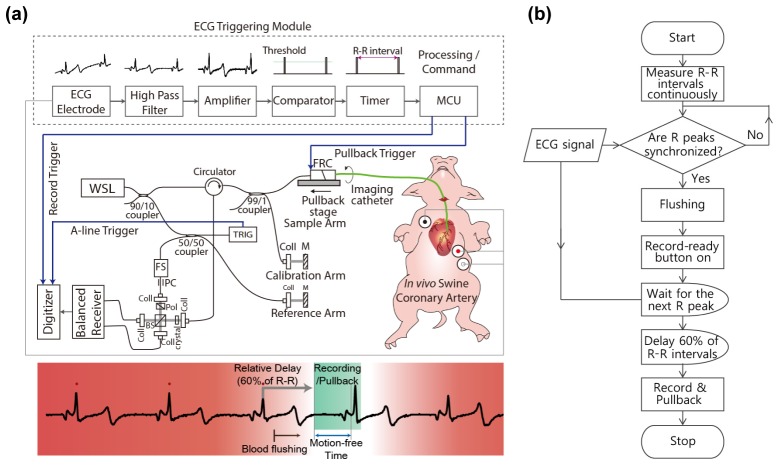
Figure 1(a) shows schematic of the high-speed intracoronary OCT system [16,17] that we built for this study. A lab-built short cavity length wavelength swept laser light source provides a wavelength sweep over 120 nm centered at 1290 nm with a sweep repetition rate of 243 kHz. The light from the laser was directed to the sample and reference arms, respectively. Ninety nine percent of the light power of the sample arm was directed to an FRC and the rest of it was used for laser sweep calibration and numerical dispersion compensation. An acousto-optic frequency shifter was used in the reference arm for full-range imaging by removing depth-degeneracy. Half of the light in the reference arm coupled to the reference mirror and another half was used to generate the trigger signal for data acquisition. A balanced detection scheme was implemented to reduce laser amplitude noise and auto-correlation noise. Signal from the balanced receiver was sampled by a high-speed (340 MS/s) and high-resolution (14 bit) digitizer.
Fig. 1.
(a) Schematic of the ECG triggered high-speed intracoronary OCT system. WSL, wavelength-swept laser; FRC, fiber-optic rotary coupler; TRIG, fiber Bragg grating-based A-line trigger module; FS, acousto-optic frequency shifter; PC, polarization controller; Coll, fiber collimator; BS, beam splitter; crystal, AMTIR crystal; MCU, micro controller unit. (b) Protocol for ECG-triggered image acquisition and pullback
In order to minimize bulk cardiac motion during intracoronary imaging in vivo, we implemented prospective triggering, which used the ECG signal to start image acquisition and pullback. As contraction and relaxation of myocardium cause critical movement of the coronary artery, avoiding the QT interval was the main purpose of the ECG triggering. Figure 1(b) shows the protocol for ECG-triggered image acquisition and pullback. The R wave of the ECG was used as a reference point for measuring R-R intervals and relative phase delay. The recent three R-R intervals were continuously compared to check the phase of each ECG signal and to determine regular heartbeat without any arrhythmic activity. The initiation signal was automatically authorized by the processor only if the last R peak was in phase. For the start point of data acquisition and pullback, we gave a phase delay of 60% of the R-R interval after the final R wave, which conveniently skipped the time interval of the QRS complex and T wave. Therefore, imaging was performed during a single late diastolic phase that was presumed to be cardiac motion-free. A custom-built ECG-triggering module consists of an ECG kit (PSL-iECG, Physiolab, Co., Ltd., Korea), a high-pass filter (HPF), an amplifier, a voltage comparator, a timer, and a micro controller unit (MCU). The low frequency component of the ECG signal was eliminated by the HPF. The filtered ECG was amplified by a custom-built signal amplifier. The voltage comparator detected the R peak through thresholding. R-R intervals were measured by a timer (NI 6259) to check the status of the ECG synchronization. Upon the imaging initiation command from an operator (a push of the “ECG-triggered recording” button on the user interface), the MCU (ATmega 128) started the image acquisition and pullback with predetermined delay. In this study, the heart rate of the pig was 75/min. The R-R interval was approximately 0.8 s and the 60% delay time was 0.5 s. Therefore, image acquisition and pullback were simultaneously initiated after 0.5 s from the last R peak and terminated at the manual stop signal. A time window of approximately 0.3 to 0.4 s was found to be motion free, allowing clear imaging of at least 30 to 40 mm long segment of coronary artery.
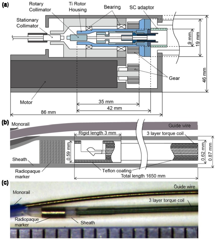
Rotational beam scanning of our OCT system relies upon a rotational coupler to connect an optical fiber from the imaging console to a catheter whose core can be continuously rotated. The rotational coupler was designed and fabricated in our laboratory to sustain rotational speeds up to ~30,000 revolutions per minute (rpm), corresponding to a frame rate of 500 images/s (484 a-lines/frame) as depicted in Fig. 2(a). For the rotary part of the coupler (bluish and bluish-green-colored parts in Fig. 2(a)), the size was minimized in both radial and axial directions and titanium was used to reduce inertia, while maintaining the strength and the rotational stability. The moment of inertia of the rotary part was 305 g-mm2, which is less than a half of our previously reported rotary part's moment of inertia (790 g-mm2) [16]. The high-speed and long translation pullback stage was implemented for a maximum pullback length of 15 cm and maximum pullback speed of 100 mm/s. A ball lens-based side-looking imaging catheter was enclosed within a 3-layer torque coil (Asahi-Intec) with polytetrafluoroethylene coating for friction reduction (Fig. 2(b), 2(c)). The rigid length of the catheter was 3 mm, which is the length of the protective distal hypotube. The whole imaging catheter was spun in the stationary sheath with a transparent distal imaging window of 0.87 mm outer diameter, which was optimized for intracoronary use. A customized cap that connects the proximal end of the catheter sheath and the housing of the rotational couple was designed and fabricated to minimize mechanical vibration at the highest rotational speed.
Fig. 2.
Fiber-optic rotary coupler and imaging catheter. (a) Schematic diagram of the high-speed fiber-optic rotary coupler. (b) Schematic diagram of distal end of the imaging catheter. (c) Picture of distal end of the imaging catheter with 1 mm scale ruler.
2.2 Swine intracoronary imaging in vivo
Intracoronary imaging of a beating swine heart was performed in vivo. The animal experiment protocol was approved by the Institutional Animal Care and Use Committee (IACUC) of Korea University Guro Hospital. The Yorkshire pig (30 kg, male; Optipharm Inc., Korea) was fed a normal chow diet. The anesthesia was induced with intramuscular tiletamine and zolazepam (Zoletil 50®, 5 mg/kg) and xylazine (2 mg/kg). After endotracheal intubation, the pig was mechanically ventilated (Vetia Anesthesia Machine with Ventilator, J&Tec. co., Ltd, Korea) with inhalation of 0.5% to 2.0% isoflurane and 100% oxygen. ECG and pulse oximetry were monitored during the procedure. The right carotid artery was exposed and a 7 French sheath introducer was inserted. Through the sheath, a 7 French guiding catheter was advanced and the tip of the catheter was placed at the left main coronary artery. The 0.014-inch guide wire was inserted into the guiding catheter and placed on the distal left anterior descending artery (LAD). A Nobori (Terumo Corporation, Tokyo, Japan) drug-eluting stent (2.5 × 14 mm) was implanted within the proximal to middle LAD. After the stent procedure, in vivo imaging of the stented coronary artery was performed through the left carotid artery. The guidewire was inserted in the LAD using the procedure mentioned above, and the OCT imaging catheter was advanced over the guidewire. The tip of the imaging catheter was placed at the distal end of the stent and ECG-triggered high-speed OCT system (500 frames/s or 500 rps, 100 mm/s) was repeatedly performed (n = 4). In order to mimic conventional OCT system operation for comparison, low speed imaging (100 frames/s or 100 rps, 20 mm/s) was also performed. To visualize the effect of systolic and diastolic motion, OCT images were acquired on the stent edge without pullback. For the clearance of the blood, iodinated contrast media (Pamiray 370: Iopamidol 755 mg/ml (370 mg as iodine)) was automatically injected at 3ml/s during ECG-triggered image acquisition and pullback.
We also performed high-speed OCT imaging of a right coronary artery in a swine model. The Yucatan minipig (20 kg, male) was used as a specimen and went through the same anesthetic procedure as the previous experiment. Through the left femoral artery, a guiding catheter was inserted into the right coronary artery (RCA). The proximal-to-middle RCA was imaged with the same protocol as above.
2.3 Image post-processing
Each pullback data set was initially processed to generate circular cross-sectional images and the longitudinal section was obtained from a series of cross-sectional images [18]. En face images were created by mean intensity projection of each A-line. The 3D images were reconstructed using a volume-rendering software (Osirix 5.6, The Osirix Foundation, Geneva, Switzerland).
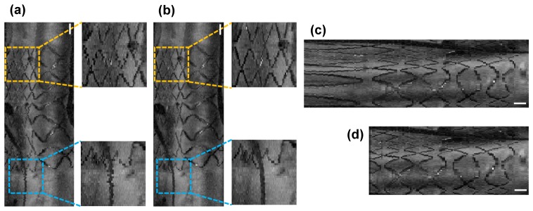
While the non-uniform rotation of the imaging catheter was minimized through the structural design and fabrication of the rotary coupler and imaging catheter as well as the reduction of the friction between the torque coil and the sheath, a small amount of non-uniform rotational distortion (NURD) [19] was unavoidable as we increased the rotation rate up to 500 rps, as shown in Fig. 3(a). We developed a NURD correction algorithm that uses the trace of the guide wire as a marker to remove this residual inter-frame NURD in the images. First, we segmented the guidewire and plotted the trace of its angular locations over longitudinal positions. Since the trace of the guidewire can be assumed to be relatively smooth, we treated high frequency distortion on the guidewire trace as an artifact caused by the inter-frame NURD. The true angular location of the guidewire without NURD was estimated by applying moving average along the trace and the high frequency fluctuation of the rotational speed was obtained as the offset of the guidewire angular location from the true location. A significant reduction of the artifacts caused by the inter-frame NURD was achieved by resizing the intervals between guidewire segments of the adjacent frames in a way that minimized the high frequency fluctuation of the rotational speed. Figure 3(b) shows the image after the NURD correction algorithm was applied. The finite longitudinal acceleration of the catheter core during pullback resulted in a consistent lag between pullback initiation and steady-state longitudinal velocity of 100 mm/s. Therefore, the longitudinal frame pitch was non-uniform at the start of scan, creating non-uniform pullback distortion in longitudinal, en face, or 3D images. Acceleration of the pullback stage was pre-measured and corrected in the final images. The pullback rate of the translational stage was measured by imaging a transparent ruler phantom, as shown in Fig. 3(c). The initial 7-8 mm of the image was affected by the transient response of the pullback speed. After adjustment of the longitudinal pitches between adjacent frames according to the calculated pullback rate from the image, the elongated portion of the image was properly corrected as shown in Fig. 3(d).
Fig. 3.
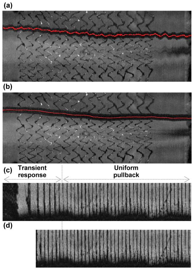
Image distortion correction. En face projections of an ex vivo coronary artery tissue sample with stent deployed (a) before and (b) after guide wire based NURD correction. En face projections of a 1 cm scaled ruler phantom (c) before and (d) after non-uniform pullback distortion correction.
3. Result
Cross-sectional and longitudinal OCT images of a swine coronary artery acquired after stent implantation are shown in Fig. 4. ECG-triggered high-speed protocol (rotation rate: 500 rps, pullback speed: 100 mm/s, imaging time: 0.7 s) and conventional protocol (rotation rate: 100 rps, pullback speed: 20 mm/s, imaging time: 3.5 s) were compared. Each high-speed cross-sectional image consists of 493 A-lines, which is similar to the A-line density of the commercial intracoronary OCT systems. The cross-sectional OCT images acquired from the high-speed protocol showed comparable image quality compared to images from the conventional-speed protocol as shown in Fig. 4(a), 4(b), 4(d), 4(e)). The intimal, medial, and adventitial layers of the coronary artery were easily distinguished in both high-speed and conventional-speed images. Stent struts were also clearly distinguishable from other vascular tissues in both images. In the longitudinal reconstruction of ECG-triggered high-speed images, the coronary vessel contour was maintained smooth along all pullback length (Fig. 4(c)). However, in conventional speed imaging (Fig. 4(f)), the vascular contour was severely distorted according to coincident QRS complexes (red arrow) and T waves (blue arrow). Furthermore, the amount of contrast dye for flushing with an automatic injector in the intracoronary OCT imaging was much smaller in high-speed imaging than in conventional imaging; median 21 ml for conventional (n = 4) and 14 ml for high-speed (n = 5) imaging (p = 0.02 by Mann-Whitney test). The synchronization of blood flushing and image acquisition along with ECG-triggering, which is not currently implemented, would further decrease the required volume of contrast dye.
Fig. 4.
Cross-sectional and longitudinal OCT images of a swine coronary artery in vivo. (a-c) Images acquired with the ECG-triggered high-speed (500 fps) protocol. (d-f) Images acquired with the conventional-speed (100 fps) protocol. (g) Angiography of a swine left anterior descending artery. Pullback segment (yellow arrow) and stented segment (blue dashed line) are indicated. Scale bars, 500 μm(a,b,d,e), 5 mm(c,f) .
A small amount of NURD in high-speed imaging interrupted the smooth connection of the identified stent struts and detailed architecture of the coronary artery in the en face projection and the 3D volume rendering as shown in Fig. 5(a). Correction of the inter-frame NURD by removing high frequency fluctuation of the rotational speed provided enhanced visualization of fine structures of the stent and the guidewire (Fig. 5(b)). The non-uniform pullback distortion due to the finite acceleration of the pullback stage was identified when the pullback was initiated inside the stent (Fig. 5(c)) and corrected (Fig. 5(d)).
Fig. 5.
(a) An en face projection of a stented coronary segment before NURD correction in the ECG-triggered high speed OCT imaging (500 rps). Stent structure (yellow dashed box) and a guidewire (blue dashed box) are shown as if they are in zigzag shapes. (b) An en face projection of the same stented coronary segment after NURD correction. Stent structure (yellow dashed box) and a guidewire (blue dashed box) are smoothly connected. (c) An en face projection before non-uniform pullback distortion correction. (d) An en face projection after non-uniform pullback distortion correction. Scale bars, 1 mm.
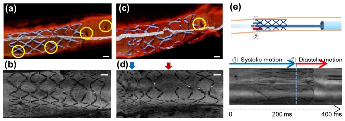
Figure 6 shows the 3D longitudinal cutaway view and the en face projection of the stented-region of the coronary artery. While the 3D structure of the vessel wall, stent deployed, and guidewire looked smooth and realistic in the ECG-triggered high-speed OCT imaging, the stent structure was severely distorted by cardiac motion and the guidewire looked distorted as if it was frequently kinked in the conventional imaging (Fig. 6(a), 6(c)). The small side branch arteries were more frequently identified in the high-speed imaging than in the conventional imaging (Yellow circles in Fig. 6(a)). The en face projections show that systolic (red arrow) and diastolic (blue arrow) motions of the heart during the pullback severely distorted the map of the stent structure in conventional-speed imaging whereas the fast pullback during the motion-free interval provided visualization of the whole stent structure without distortion induced by the cardiac motion (Fig. 6(b), 6(d)).
Fig. 6.
(a) Cutaway longitudinal view of the stented region acquired from the ECG-triggered high-speed (500 fps) OCT showing many perforating side branches (yellow circle). (b) En face projection of the stented coronary region showing whole stent struts acquired from the ECG-triggered high-speed imaging. (c) Cutaway longitudinal view of the same stented region acquired from the conventional speed (100 fps) OCT showing less frequently detected perforating side branches (yellow circle). (d) En face projection of the same stented coronary region acquired from the conventional speed imaging. During the systolic motion (blue arrow), stent struts are not smoothly connected. During the diastolic motion (red arrow), several struts seemed to be skipped or artificially elongated. Scale bars, 1 mm. (e) Imaging cardiac motion without pullback. The imaging catheter tip was placed right outside of the distal edge of the implanted stent. During systole, coronary artery moved toward apex of the heart and the tip of imaging catheter entered stented segment (blue arrow). During diastole, coronary artery moved back toward base of the heart and the tip of imaging catheter leaved stented segment (red arrow).
To simulate the effect of the cardiac motion, OCT images were acquired without pullback in the vicinity of stent edge as depicted in Fig. 6(e). During systole, the imaging catheter tip moved from the unstented region into the stented region. During diastole, the imaging catheter tip came out of the stented region and stayed at the unstented region with minimal longitudinal motion (Fig. 6(f)). This result helps interpretation of the images obtained with the conventional speed. The systolic motion of the vessel effectively increased the pullback speed and resulted in an increase of longitudinal pitch that markedly disconnected stent struts in 3D and en face projection images. The diastolic motion, which slid the catheter tip opposite to the pullback direction relative to the vessel wall, effectively reduced the pullback speed and decreased longitudinal pitch that resultantly elongated stent structures in the images.
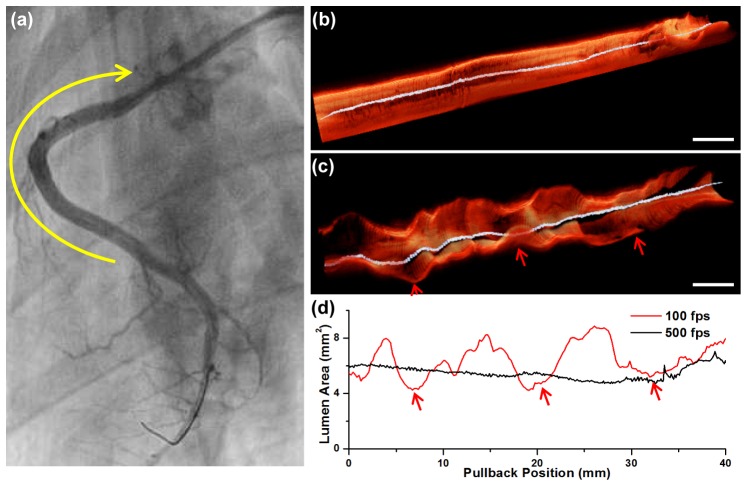
High-speed imaging also provides a more realistic visualization of the 3D luminal morphology. In a right coronary artery of a Yukatan minipig, no significant stenotic lesion was observed from the angiography, as shown in Fig. 7(a). We performed high-speed OCT imaging in the proximal-to-middle RCA (yellow arrow). The 3D image acquired from the high-speed imaging shows smooth luminal morphology along the length of the vessel without showing any noticeable stenosis (Fig. 7(b)), which agrees with the angiography. In comparison, the 3D longitudinal cutaway image acquired with the conventional protocol was severely distorted as if there were multiple stenotic lesions (Fig. 7(c)). The lumen area plot obtained through automatic lumen segmentation [18] also showed that the lumen area measurement was severely affected by the cardiac motion in the conventional imaging showing false stenotic lesions (Fig. 7(d)).
Fig. 7.
(a) Angiography of the right coronary artery (RCA). There was no significant coronary artery stenosis observed. OCT was acquired in the proximal-to-middle RCA (yellow arrow). (b) 3D cutaway longitudinal image of the ECG-triggered high-speed OCT. (c) 3D cutaway longitudinal image of the conventional speed OCT. The 3D luminal morphology was severely distorted by the repeated cardiac motion (red arrows). (d) Lumen area plot along the whole coronary pullback obtained by the automatic lumen segmentation. The lumen area value obtained from the conventional speed imaging largely fluctuated with respect to the cardiac motion (red arrows), whereas smooth and stable when obtained from the ECG-triggered high-speed imaging. Scale bars, 5 mm (b), (c).
4. Discussion
We have demonstrated the high-speed intracoronary OCT for cardiac motion-free coronary artery imaging in vivo. Although 3D visualization of coronary microstructure has been available since the demonstration of the 2G-OCT, its clinical utility has been limited and remains undefined mainly due to severe motion artifacts caused by the heartbeat. With a combination of high-speed OCT system, high-speed FRC, optimized high-speed imaging catheter, and prospective ECG-triggering, coronary artery imaging at a rate of 500 frames/s and a pullback speed of 100 mm/s was achieved, enabling imaging of long coronary artery segments during the period of minimal motion artifact within a single cardiac cycle (70 mm pullback in 0.7 s). This technique and imaging strategy may enhance the utility of 3D intracoronary OCT in clinics such for accurate diagnosis of coronary lesions based on 3D perspective of the plaque morphology [2,17,20,21], global evaluation of stent deployment [4,6,22], and quantitative assessment of 3D luminal dimension [23,24] which can be complicated with the current intracoronary OCT.
In the present study, the longitudinal imaging pitch (200 μm) was the same as that in the conventional 3D intracoronary OCT imaging for the motion-free imaging of long coronary artery segment (70 mm in 0.7 s). In order to obtain true 3D high resolution imaging by matching the longitudinal imaging pitch to the spatial resolution of the intracoronary OCT system (~30 μm), several times denser sampling in the longitudinal direction is required. Motion-free and true 3D high-resolution intracoronary OCT imaging, therefore, requires over 3,000 frames/s imaging speed. Recently, an intravascular OCT using a beam-scanning micromotor at the distal tip of the imaging catheter demonstrated ultrahigh-speed imaging of swine coronary artery in vivo at an imaging speed up to 4,000 frames/s [15,25]. Whereas the ultrahigh-speed beam scanning using a distal micromotor can be a good candidate for the motion-free and true 3D high-resolution intracoronary OCT, there are several issues as the current form, such as large rigid distal catheter tip, guidewire compatibility, four additional shadows created by the motor wires, and safety of supplying high current for the distal scanning motor operation, that this approach needs to resolve for potential clinical intracoronary imaging. Further increase of the rotational speed of the imaging catheter could be also pursued in the proximal beam scanning approach using an FRC. The higher speed motor and driver, further reduction of rotary part's moment of inertia in the FRC, and further reduction of friction between the torque coil and the sheath are required for the higher speed intracoroanry imaging with the proximal beam scanning approach.
The 3D visualization of coronary artery is intuitively easy to understand and provides a global perspective of the coronary lesions and their morphologies. However, accurate and quantitative 3D assessment of the coronary artery and the lesions minimizing the diagnostic uncertainty is only possible with proper removal of motion artifacts. We expect the motion-free high-speed intracoronary OCT with the ECG-triggered imaging to bring potential of 3D intracoronary OCT to clinical reality along with the recent development of high-speed 3D intracoronary OCT image processing and visualization [18]. In vivo swine intracoronary imaging with correctable NURD demonstrates the high stability and safety of the system, showing the maturity of this technology for potential clinical application.
5. Conclusion
We demonstrate development and characterization of the prospective ECG-triggered high-speed intracoronary OCT system. The fiber optic rotary coupler-based high-speed intracoronary OCT system enabled volumetric imaging of long coronary artery segments within only a portion of a single cardiac cycle (70 mm pullback in 0.7 s) with minimal cardiac motion artifact. This imaging technique reveals 3D microstructure of coronary and implanted stent in a beating swine heart and is readily translatable to the clinics.
Acknowledgments
This study was supported by the National Research Foundation of Korea (grant 2010-0017465 and grant 2012R1A2A2A04046108), the Ministry of Health and Welfare of Korea (grant HI15C0001), and the National Institutes of Health (grant P41 EB015903).
References and links
- 1.Jang I.-K., Bouma B. E., Kang D.-H., Park S.-J., Park S.-W., Seung K.-B., Choi K.-B., Shishkov M., Schlendorf K., Pomerantsev E., Houser S. L., Aretz H. T., Tearney G. J., “Visualization of Coronary Atherosclerotic Plaques in Patients Using Optical Coherence Tomography: Comparison with Intravascular Ultrasound,” J. Am. Coll. Cardiol. 39(4), 604–609 (2002). 10.1016/S0735-1097(01)01799-5 [DOI] [PubMed] [Google Scholar]
- 2.Tearney G. J., Waxman S., Shishkov M., Vakoc B. J., Suter M. J., Freilich M. I., Desjardins A. E., Oh W.-Y., Bartlett L. A., Rosenberg M., Bouma B. E., “Three-dimensional coronary artery microscopy by intracoronary optical frequency domain imaging,” JACC Cardiovasc. Imaging 1(6), 752–761 (2008). 10.1016/j.jcmg.2008.06.007 [DOI] [PMC free article] [PubMed] [Google Scholar]
- 3.Yun S. H., Tearney G. J., Vakoc B. J., Shishkov M., Oh W. Y., Desjardins A. E., Suter M. J., Chan R. C., Evans J. A., Jang I. K., Nishioka N. S., de Boer J. F., Bouma B. E., “Comprehensive volumetric optical microscopy in vivo,” Nat. Med. 12(12), 1429–1433 (2007). 10.1038/nm1450 [DOI] [PMC free article] [PubMed] [Google Scholar]
- 4.Okamura T., Onuma Y., García-García H. M., Regar E., Wykrzykowska J. J., Koolen J., Thuesen L., Windecker S., Whitbourn R., McClean D. R., Ormiston J. A., Serruys P. W., “3-Dimensional optical coherence tomography assessment of jailed side branches by bioresorbable vascular scaffolds: a proposal for classification,” JACC Cardiovasc. Interv. 3(8), 836–844 (2010). 10.1016/j.jcin.2010.05.011 [DOI] [PubMed] [Google Scholar]
- 5.Tearney G. J., Regar E., Akasaka T., Adriaenssens T., Barlis P., Bezerra H. G., Bouma B., Bruining N., Cho J. M., Chowdhary S., Costa M. A., de Silva R., Dijkstra J., Di Mario C., Dudek D., Falk E., Feldman M. D., Fitzgerald P., Garcia-Garcia H. M., Gonzalo N., Granada J. F., Guagliumi G., Holm N. R., Honda Y., Ikeno F., Kawasaki M., Kochman J., Koltowski L., Kubo T., Kume T., Kyono H., Lam C. C., Lamouche G., Lee D. P., Leon M. B., Maehara A., Manfrini O., Mintz G. S., Mizuno K., Morel M. A., Nadkarni S., Okura H., Otake H., Pietrasik A., Prati F., Räber L., Radu M. D., Rieber J., Riga M., Rollins A., Rosenberg M., Sirbu V., Serruys P. W., Shimada K., Shinke T., Shite J., Siegel E., Sonoda S., Suter M., Takarada S., Tanaka A., Terashima M., Thim T., Uemura S., Ughi G. J., van Beusekom H. M., van der Steen A. F., van Es G. A., van Soest G., Virmani R., Waxman S., Weissman N. J., Weisz G., International Working Group for Intravascular Optical Coherence Tomography (IWG-IVOCT) , “Consensus standards for acquisition, measurement, and reporting of intravascular optical coherence tomography studies: a report from the International Working Group for Intravascular Optical Coherence Tomography Standardization and Validation,” J. Am. Coll. Cardiol. 59(12), 1058–1072 (2012). 10.1016/j.jacc.2011.09.079 [DOI] [PubMed] [Google Scholar]
- 6.Farooq V., Gogas B. D., Okamura T., Heo J. H., Magro M., Gomez-Lara J., Onuma Y., Radu M. D., Brugaletta S., van Bochove G., van Geuns R. J., Garcìa-Garcìa H. M., Serruys P. W., “Three-dimensional optical frequency domain imaging in conventional percutaneous coronary intervention: the potential for clinical application,” Eur. Heart J. 34(12), 875–885 (2013). 10.1093/eurheartj/ehr409 [DOI] [PubMed] [Google Scholar]
- 7.Prasad A., Phipps J., “Limiting contrast dye exposure every way we can: use of dextran during coronary optical coherence tomography imaging,” Catheter. Cardiovasc. Interv. 84(5), 732–733 (2014). 10.1002/ccd.25653 [DOI] [PubMed] [Google Scholar]
- 8.McCullough P. A., “Contrast-induced acute kidney injury,” J. Am. Coll. Cardiol. 51(15), 1419–1428 (2008). 10.1016/j.jacc.2007.12.035 [DOI] [PubMed] [Google Scholar]
- 9.Ohno Y., Mangiameli A, Attizzani G. F., Capodanno D., Tamburino C., “Optical coherence tomography assessment of late intra-scaffold dissection: a new challenge of bioresorbable scaffolds,” JACC Cardiovasc. Interv. 8(1), e11–e12 (2015). [DOI] [PubMed] [Google Scholar]
- 10.Jang S. J., Park H.-S., Song J. W., Kim T. S., Cho H. S., Kim S., Bouma B. E., Kim J. W., Oh W.-Y., “ECG-triggered, single cardiac cycle, high-speed, 3D, intracoronary OCT,” JACC Cardiovasc. Imaging 9(5), 623–625 (2016). 10.1016/j.jcmg.2015.11.021 [DOI] [PMC free article] [PubMed] [Google Scholar]
- 11.Desjardins B., Kazerooni E. A., “ECG-gated cardiac CT,” AJR Am. J. Roentgenol. 182(4), 993–1010 (2004). 10.2214/ajr.182.4.1820993 [DOI] [PubMed] [Google Scholar]
- 12.Lackner K., Thurn P., “Computed tomography of the heart: ECG-gated and continuous scans,” Radiology 140(2), 413–420 (1981). 10.1148/radiology.140.2.6973166 [DOI] [PubMed] [Google Scholar]
- 13.von Birgelen C., Mintz G. S., Nicosia A., Foley D. P., van der Giessen W. J., Bruining N., Airiian S. G., Roelandt J. R. T. C., de Feyter P. J., Serruys P. W., “Electrocardiogram-gated intravascular ultrasound image acquisition after coronary stent deployment facilitates on-line three-dimensional reconstruction and automated lumen quantification,” J. Am. Coll. Cardiol. 30(2), 436–443 (1997). 10.1016/S0735-1097(97)00154-X [DOI] [PubMed] [Google Scholar]
- 14.Wang T., Pfeiffer T., Regar E., Wieser W., van Beusekom H., Lancee C. T., Springeling G., Krabbendam-Peters I., van der Steen A. F., Huber R., van Soest G., “Heartbeat OCT and motion-free 3D in vivo coronary artery microscopy,” JACC Cardiovasc. Imaging 9(5), 622–623 (2016). 10.1016/j.jcmg.2015.08.010 [DOI] [PubMed] [Google Scholar]
- 15.Wang T., Pfeiffer T., Regar E., Wieser W., van Beusekom H., Lancee C. T., Springeling G., Krabbendam I., van der Steen A. F., Huber R., van Soest G., “Heartbeat OCT: in vivo intravascular megahertz-optical coherence tomography,” Biomed. Opt. Express 6(12), 5021–5032 (2015). 10.1364/BOE.6.005021 [DOI] [PMC free article] [PubMed] [Google Scholar]
- 16.Cho H. S., Jang S. J., Kim K., Dan-Chin-Yu A. V., Shishkov M., Bouma B. E., Oh W. Y., “High frame-rate intravascular optical frequency-domain imaging in vivo,” Biomed. Opt. Express 5(1), 223–232 (2014). 10.1364/BOE.5.000223 [DOI] [PMC free article] [PubMed] [Google Scholar]
- 17.Lee S., Lee M. W., Cho H. S., Song J. W., Nam H. S., Oh D. J., Park K., Oh W.-Y., Yoo H., Kim J. W., “Fully integrated high-speed intravascular optical coherence tomography/near-infrared fluorescence structural/molecular imaging in vivo using a clinically available near-infrared fluorescence-emitting indocyanine green to detect inflamed lipid-rich atheromata in coronary-sized vessels,” Circ. Cardiovasc. Interv. 7(4), 560–569 (2014). 10.1161/CIRCINTERVENTIONS.114.001498 [DOI] [PubMed] [Google Scholar]
- 18.Han M., Kim K., Jang S.-J., Cho H. S., Bouma B. E., Oh W. Y., Ryu S., “GPU-accelerated framework for intracoronary optical coherence tomography imaging at the push of a button,” PLoS One 10(4), e0124192 (2015). 10.1371/journal.pone.0124192 [DOI] [PMC free article] [PubMed] [Google Scholar]
- 19.van Soest G., Bosch J. G., van der Steen A. F., “Azimuthal registration of image sequences affected by nonuniform rotation distortion,” IEEE Trans. Inf. Technol. Biomed. 12(3), 348–355 (2008). 10.1109/TITB.2007.908000 [DOI] [PubMed] [Google Scholar]
- 20.Jia H., Abtahian F., Aguirre A. D., Lee S., Chia S., Lowe H., Kato K., Yonetsu T., Vergallo R., Hu S., Tian J., Lee H., Park S. J., Jang Y. S., Raffel O. C., Mizuno K., Uemura S., Itoh T., Kakuta T., Choi S. Y., Dauerman H. L., Prasad A., Toma C., McNulty I., Zhang S., Yu B., Fuster V., Narula J., Virmani R., Jang I. K., “In vivo diagnosis of plaque erosion and calcified nodule in patients with acute coronary syndrome by intravascular optical coherence tomography,” J. Am. Coll. Cardiol. 62(19), 1748–1758 (2013). 10.1016/j.jacc.2013.05.071 [DOI] [PMC free article] [PubMed] [Google Scholar]
- 21.Gonzalo N., Tearney G. J., van Soest G., Serruys P., Garcia-Garcia H. M., Bouma B. E., Regar E., “Witnessed Coronary Plaque Rupture During Cardiac Catheterization,” JACC Cardiovasc. Imaging 4(4), 437–438 (2011). 10.1016/j.jcmg.2010.11.021 [DOI] [PubMed] [Google Scholar]
- 22.Farooq V., Onuma Y., Radu M., Okamura T., Gomez-Lara J., Brugaletta S., Gogas B. D., van Geuns R. J., Regar E., Schultz C., Windecker S., Lefèvre T., Brueren B. R., Powers J., Perkins L. L., Rapoza R. J., Virmani R., García-García H. M., Serruys P. W., “Optical coherence tomography (OCT) of overlapping bioresorbable scaffolds: from benchwork to clinical application,” EuroIntervention 7(3), 386–399 (2011). 10.4244/EIJV7I3A64 [DOI] [PubMed] [Google Scholar]
- 23.Guagliumi G., Sirbu V., Petroff C., Capodanno D., Musumeci G., Yamamoto H., Elbasiony A., Brushett C., Matiashvili A., Lortkipanidze N., Valsecchi O., Bezerra H. G., Schmitt J. M., “Volumetric assessment of lesion severity with optical coherence tomography: relationship with fractional flow,” EuroIntervention 8(10), 1172–1181 (2013). 10.4244/EIJV8I10A181 [DOI] [PubMed] [Google Scholar]
- 24.Gonzalo N., Escaned J., Alfonso F., Nolte C., Rodriguez V., Jimenez-Quevedo P., Bañuelos C., Fernández-Ortiz A., Garcia E., Hernandez-Antolin R., Macaya C., “Morphometric assessment of coronary stenosis relevance with optical coherence tomography: a comparison with fractional flow reserve and intravascular ultrasound,” J. Am. Coll. Cardiol. 59(12), 1080–1089 (2012). 10.1016/j.jacc.2011.09.078 [DOI] [PubMed] [Google Scholar]
- 25.Wang T., Wieser W., Springeling G., Beurskens R., Lancee C. T., Pfeiffer T., van der Steen A. F. W., Huber R., van Soest G., “Intravascular optical coherence tomography imaging at 3200 frames per second,” Opt. Lett. 38(10), 1715–1717 (2013). 10.1364/OL.38.001715 [DOI] [PubMed] [Google Scholar]


