Abstract
We investigate the potential of mobile smartphone-based multispectral imaging for the quantitative diagnosis and management of skin lesions. Recently, various mobile devices such as a smartphone have emerged as healthcare tools. They have been applied for the early diagnosis of nonmalignant and malignant skin diseases. Particularly, when they are combined with an advanced optical imaging technique such as multispectral imaging and analysis, it would be beneficial for the early diagnosis of such skin diseases and for further quantitative prognosis monitoring after treatment at home. Thus, we demonstrate here the development of a smartphone-based multispectral imaging system with high portability and its potential for mobile skin diagnosis. The results suggest that smartphone-based multispectral imaging and analysis has great potential as a healthcare tool for quantitative mobile skin diagnosis.
OCIS codes: (110.4234) Multispectral and hyperspectral imaging, (170.1870) Dermatology
1. Introduction
Over the last few decades, spectral imaging and analysis techniques have been widely utilized as quantitative optical imaging tools for various biomedical applications [1]. These techniques allow a spectral signature to be obtained at each pixel in an image. As a result, an image cube that contains spectral as well as spatial information can be obtained. In particular, the spectral information can be applied quantitatively to distinguish a biological specimen of interest from the background, which cannot be discriminated with conventional monochrome and RGB color imaging methods [2, 3], as different biological constituents typically reflect distinguishable spectral signatures. In spectral analyses, various methods based on distance measures have been applied to achieve the quantitative and robust segmentation of regions of interest in an image cube [1]. Moreover, advanced spectral classification methods such as linear de-combination or principal component analysis have been shown to be capable of separating very closely spaced spectral signatures [4].
The spectral imaging and analysis technique has therefore been used to diagnose various diseases such as gastric carcinomas [5], breast cancer [6], and skin diseases non-invasively [7]. In particular, it was shown to have great potential to both spatially and spectrally resolve heterogeneous skin lesions among indiscernible features by exploiting predefined spectral reflectance characteristics during the diagnosis of various malignant and non-malignant skin diseases [2, 8–12]. For example, the spectral imaging and analysis technique was found to be capable of differentiating melanoma, which is one of the most malignant skin diseases, from dysplastic nevi and melanocytic nevi at an early stage [8]. The study reported that the automatic differentiation of in situ melanomas from melanocytic nevi can be realized using the spectral imaging and analysis method. This method was also applied to evaluate the severity of acne lesions by applying a combination of linear discriminant functions. Using spectral imaging and a linear discriminant function classifier, a variety of acne lesion types were successfully extracted and classified [9, 10]. Moreover, a multi-spectral imaging and analysis method in the visible and near infrared wavelength ranges has been shown to be a useful noninvasive tool in the study of edema pathology. It allowed a quantitatively discrimination between erythema and edema in vivo and thus enabled an improvement in the efficacy of treatments in a clinical setting [11]. Multispectral imaging and analysis techniques were also utilized for a quantitative diagnosis of psoriasis, an autoimmune disease of the skin. In that study, it allowed the monitoring of the effects of personalized treatments of psoriasis [12].
Recently, various mobile devices based on a smartphone, which allow one to obtain individual healthcare information, have emerged and garnered much attention [13–17]. Therefore, many researchers have made efforts to develop such smartphone-based devices. In particular, for the early detection of skin lesions, several handheld skin diagnosis systems based on a smartphone have been developed given that the early detection and quantitative/continuous monitoring of malignant and non-malignant skin diseases was found to be crucial in the treatment of diseases in a timely manner [18–21]. Most of the devices were based on RGB color imaging as well as conventional image processing techniques [17, 22, 23]. However, conventional monochromatic or RGB color imaging has several limitations with regard to the early detection and verification of skin lesions, such as low spectral resolutions and less versatility when used to diagnose various skin diseases [24]. To overcome these limitations, the development of a more advanced mobile skin diagnosis system with high quantitative capabilities must be pursued.
We thus investigate the potential of smartphone-based multispectral imaging and analysis for mobile skin diagnosis and the quantitative monitoring of skin lesions of interest. In particular, the development of a mobile multispectral imaging system attached to a smartphone for mobile skin diagnosis with high accuracy is demonstrated and its performance is evaluated. Furthermore, potential applications are examined. Note that multispectral imaging and analysis techniques have been shown to have great potential for quantitative and accurate diagnoses of such skin diseases. Recently, only a few researchers have explored the development of such multispectral imaging systems based on smartphones for mobile diagnoses of skin lesions. However, its applications and performance capabilities still require improvements [25]. In the development of the system, a compact multispectral imaging system which utilizes a smartphone’s camera and light source was built and attached to a smartphone. In addition, an interface circuit was designed for synchronization and communication between the smartphone and a miniaturized multispectral imaging system. An Android application was also developed to control the attached multispectral imaging system, provide communication between the smartphone and a server computer, and display the outcomes after the skin analysis. A skin analysis/diagnosis/management platform was also built for spectral classification and data storage. A simple but key calibration method for smartphone-based multispectral imaging was demonstrated. Moreover, to demonstrate the potential applications of the developed system, it was employed for quantitative diagnoses of both nevus and acne regions. In particular, a ratiometric spectral imaging and analysis technique was adopted to achieve better a quantitative analysis of acne regions, demonstrating that smartphone-based multispectral imaging and analysis has great potential in the areas of quantitative mobile skin diagnosis and continuous management.
2. Methods and results
2.1 Smartphone-attached multispectral imaging system
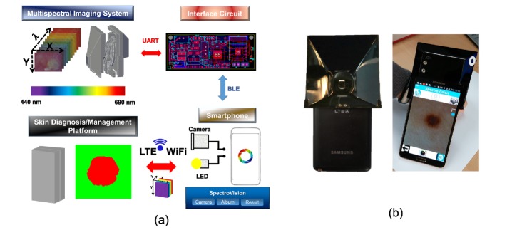
The smartphone-attached multispectral imaging system mainly includes a home-built multispectral imaging system, a smartphone (Samsung, SM-N900S), an Android application, and a skin diagnosis/management platform, as shown in Fig. 1(a). The home-built multispectral imaging system is capable of being attached to a smartphone. It should be noted that the system utilizes a CMOS camera and the LED source of the smartphone for image acquisition and illumination on the skin regions of interest, respectively. Synchronization and wireless communication between the smartphone and the multispectral imaging system are realized through an interface circuit that we built. Wireless communication is achieved here by a Bluetooth module (Chipsen BLE 110) incorporated into the interface circuit. The interface circuit transmits control commands to a motor control unit in the multispectral imaging system after receiving the command signals from the smartphone. The motor control unit places a selected filter in the desired location. The Android application was developed to control the multispectral imaging system, perform the multispectral imaging of skin lesions, transfer image data to the server from the smartphone through either WiFi or LTE communication, and display the resultant images and spectral signatures on the smartphone screen. The skin diagnosis/management platform receives the image data transferred from the smartphone and then performs spectral classification; this is followed by the transfer of the resultant classified spectral results as well as the spectral signatures from the platform to the smartphone. A photographic image of the system as devised here is shown in Fig. 1(b).
Fig. 1.
(a) Diagram of a smartphone-attached multispectral imaging system for the diagnosis and management of skin lesions, and (b) photographic image of the proposed system
2.2 Miniaturization of a multispectral imaging system
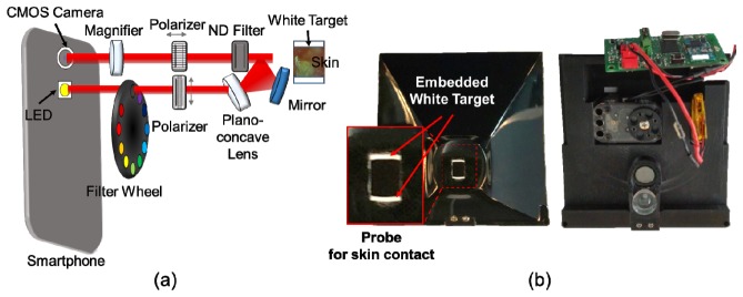
The spectral imaging system was miniaturized so that it could be attached to a smartphone, as shown in Fig. 2. The system allows users to obtain ten images sequentially within a range of wavelengths of 440 nm to 690 nm, with one white-light image. This system consists of a plano-concave lens, a mirror (Edmund Optics, 45-918/32-942), a magnifying lens, two linear polarizers (Thorlabs, LPVISE050-A), nine bandpass filters (Delta Optics), and a motorized filter wheel. Light from the LED source of the smartphone passes through a linear polarizer in the vertical direction and an optical bandpass filter in the filter wheel and the light is then delivered to skin regions of interest by a plano-concave lens and a mirror. It should be noted that the plano-concave lens and the mirror offer broad light illumination onto the skin regions. The delivered light interacts with the skin regions and is reflected or scattered by it. The light coming from the skin is collected by a 10x magnifying lens after passing through a neutral density filter and a linear polarizer at 90° in the vertical direction. Note that the linear polarizer in the horizontal direction reduces the specular-reflected light from the skin, thus allowing the device selectively to collect the light scattered from the skin [26]. The collected light is then recorded by the CMOS camera of the smartphone, as shown in Fig. 2(a). The working distance between the camera lens and the skin was 27 mm. The multispectral imaging system was enclosed by a light-tight enclosure. Therefore, when the probe indicated by the red-solid rectangle was in contact with the skin, unwanted ambient light from surrounding environment could be blocked. Moreover, the probe for skin contact included white targets for system calibration purposes, as shown in Fig. 2(b). Note that the white targets are always located within the field of view of an image obtained using the system such that both the white target and the skin regions of interest could be imaged at different wavelengths simultaneously. The intensity levels of the white target regions in the images were utilized here as the reference signals at different wavelengths for system calibration. The physical dimensions of the system were 92 x 89 x 51mm. Its weight was 130g.
Fig. 2.
Miniaturization of the multispectral imaging system: (a) schematics of the miniaturized multispectral imaging system, and (b) photographic images of developed multispectral imaging system. The magnified photographic image indicated by a red solid rectangular represents the probe region to be in contact with the skin. The arrow indicates the embedded white target.
Wavelength selection of the light illuminated onto the skin region is achieved through the use of a bandpass filter installed in the filter wheel, which is attached to a servomotor (Robotis, XL-320) for multispectral imaging. The bandpass filters were created by the dicing of a linear variable filter (Delta Optics, LF102499). The properties of the linear variable filter, varying linearly along the width, were exploited here to achieve narrow bandwidths and sequential wavelength selection capabilities [27]. The filters are 3.5 mm (width) x 4 mm (height) in size with center wavelengths of ~440 (FWHM: 9 nm), ~460 (FWHM: 9 nm), ~480 (FWHM: 10 nm), ~515 (FWHM: 12 nm), ~550 (FWHM: 14 nm), ~585 (FWHM: 15 nm), ~620 (FWHM: 18 nm), ~655 (FWHM: 18 nm), and ~690 nm (FWHM: 19 nm) (Fig. 3). A total of time for acquisition of ten images was ~6.5 seconds.
Fig. 3.
Diced linear variable bandpass filters: (a) transmission of each diced linear variable filter and size of the diced linear variable bandpass filter, and (b) inherent spectrum of the smartphone LED used in the system.
2.3 Interface circuit for synchronization between the multispectral imaging system and the smartphone
An interface circuit was devised to synchronize the miniaturized spectral imaging system and the smartphone and to control the motorized filter wheel. The system consists of a microcontroller unit (MCU) (Atmega 128), a Bluetooth low-energy (BLE) module, and other electrical components, such as voltage regulators. The MCU unit in the interface circuit receives a command signal from the smartphone through BLE communication and then, for the rotation of the motorized filter wheel, delivers the command signal to a servomotor through UART communication. A 3.7 V lithium-polymer battery is used to provide power to the interface circuit. A step-up regulator upregulates the input voltages of 3.7 V to 7.4 V and then provides a static 7.4 V to the servomotor to control the filter wheel attached to the servomotor (Fig. 4). In contrast, the low-dropout regulator downregulates the input voltage to 3.3 V to supply power to the MCU and Bluetooth modules.
Fig. 4.
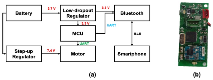
Schematics of the interface circuits: (a) circuit diagram, (b) photographic image of the interface circuit.
2.4 Platform for skin diagnosis/management
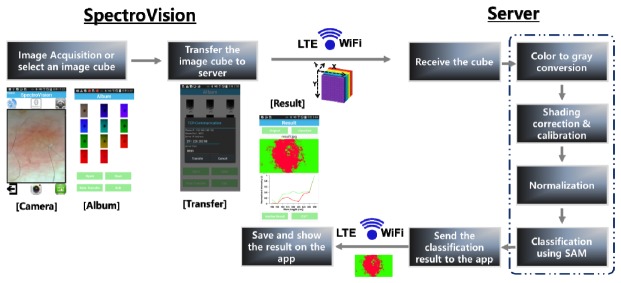
A custom-designed Android application, termed SpectroVision, was developed in order to perform multispectral imaging and analyses of skin lesions. SpectroVision allows users to obtain nine images at different/sequential wavelengths ranging from 440 nm to 690 nm (an image cube) and one white-light image by controlling the motorized filter wheel through the interface circuit under a Bluetooth connection. Note that the camera exposure time and the white balance setting were fixed during the multispectral imaging process by controlling the camera API in Android. For the spectral classification of skin lesions (Fig. 5), the acquired images are selected and then transferred to a skin diagnosis/management platform through either WiFi or LTE communication. After the platform receives an image cube from SpectroVision, preprocessing of the image cube including gray-scale conversion, shading correction, calibration, and normalization is sequentially performed. The gray-scale conversion of an RGB colored image is done via the following equation,
| (1) |
where R, G, and B represent the intensity values of the red, green, and blue pixels, respectively [28].
Fig. 5.
Illustrations of the automated spectral classification of skin lesions using the customized Android application (SpectroVision).
Shading correction to reduce the artifacts created by non-uniform illumination on the skin and spectral calibration are performed using the equation below:
| (2) |
here Ical (x, y, λ) denotes the calibrated intensity at x, y, and λ, Iorigin (x, y, λ) is the original intensity of the pixel at x, y, and λ, wc (λ) is the weight factor for calibration at the wavelength of λ, WTmax (λ) is the maximum intensity on the white target at λ. WT (x, y, λ) is the intensity of the white target at x, y, and λ.
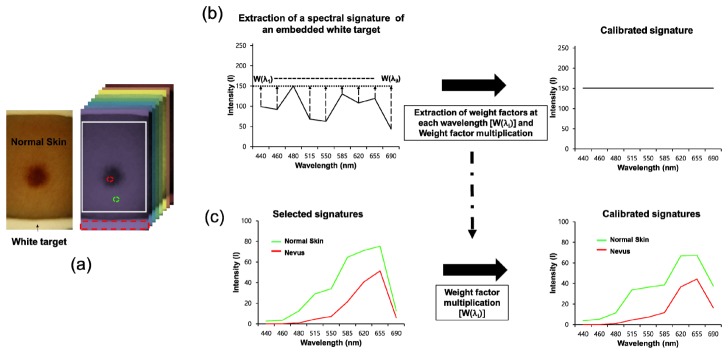
Figure 6 demonstrates the procedures for calibration of a spectral signature at every pixel. Weight factors at different wavelengths were first extracted from an image cube [Fig. 6(a), right]. In order to determine the weight factors at different wavelengths, the mean intensity of the embedded white target regions, selected by the red-dotted rectangular, in images at each wavelength was calculated and the maximum value among the mean intensities of the white target regions at the different wavelengths was then found. The maximum value was divided by the mean intensity at each wavelength such that the weight factors at the indicated wavelengths were obtained in each case. The original intensity of the embedded white target at each wavelength was then multiplied by the weight factor at the corresponding wavelength and thus the calibrated spectral signature of the embedded white target with an identical intensity at different wavelengths could be obtained as shown in Fig. 6(b) (right). In addition, for calibration of the spectral signature at every pixel, the intensity of every pixel at each wavelength was multiplied by the weight factor extracted from the embedded white target at the corresponding wavelength. Therefore, the calibrated signatures of the skin regions at every pixel could be obtained [Fig. 6(c)]. These calibration procedures were carried out whenever multispectral imaging was performed to acquire a calibrated spectral signature at every pixel.
Fig. 6.
Calibration of spectral signatures at every pixel: (a) Photographic image of skin regions obtained using our system and an image cube. The arrow indicates the embedded white target in the image. The red-dotted rectangular represents the area selected for calculation of the mean intensity of the embedded white target. The red- and green-dotted circles indicate the regions selected to obtain the spectral signatures of normal skin and nevus regions. (b) Extraction of weight factors at different wavelengths from the embedded white target. w(λi): weight factor at the ith wavelength (λ) (c) Calibration of a selected spectral signature. Intensity of the selected spectral signature at each wavelength was multiplied by the weight factor at the identical wavelength.
After preprocessing, spectral classification of the image cube is performed with predefined reference spectral signatures in the platform. For the spectral classification, a spectral angle measure (SAM) is utilized here. In the SAM, spectral angles between spectral signatures measured at every pixel and reference spectral signatures are calculated with the following equation [29]:
| (3) |
In this equation, si is the spectral signature of the i-th pixel, μj is the j-th reference spectral signature, and L is the number of spectral dimensions of the image. After the measurement of the spectral angles, a predefined color for the reference signature having the minimum angle with the measured spectral signature is assigned to the corresponding pixel. Finally, the classified image is transferred to the SpectroVision application and the resultant classified image and corresponding spectral signatures used for the classification are then displayed in the application.
2.5 Evaluation of the performance of the smartphone-based multispectral imaging system
To examine the optical resolution of the smartphone-based multispectral imaging system, the highest frequency line set which the system is capable of resolving in a resolution target (Thorlabs, R2L2S1P1) was measured. Figure 7 illustrates an image of the resolution target [Fig. 7(a)] and profiles of the intensities along the vertical and horizontal solid lines (A’ and B’) at the frequency line set of 51, indicating 51 cycles/mm [Figs. 6(b) and 6(c)]. In the intensity profiles, the lines in the vertical (A’) and horizontal (B’) directions are clearly distinguished, as shown in Figs. 7(b) and 7(c). A total of five lines could be distinguished in the vertical and horizontal directions at the frequency set of 51 using the system. Therefore, these results demonstrate that this system is capable of resolving 51 cycles per millimeter.
Fig. 7.
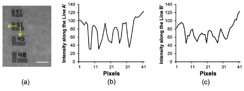
Resolution of a smartphone-based multispectral imaging system: (a) cropped image of a resolution target, (b) intensity variations along the line of A’ (horizontal direction) in the image acquired using the proposed system, and (c) intensity variations along the line of B’ (vertical direction) in the image acquired using the developed system. The scale bar indicates ~300 μm.
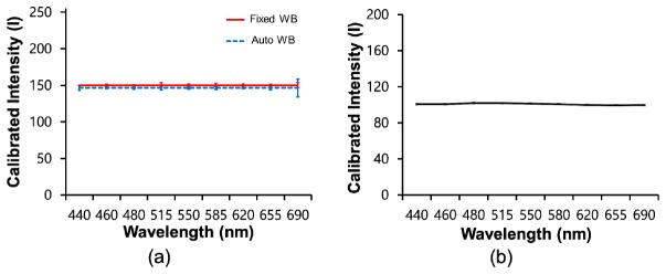
In addition, the reproducibility during the construction of spectral signatures, which can be offered by the smartphone-based multispectral imaging system after its calibration with an embedded white target, was examined. For the examination of the reproducibility of the system, a total of 10 spectral signatures for a white target were repeatedly acquired using the system with fixed and automated white balance settings, after which the mean spectral signatures and their standard deviations were compared to the outcome obtained using a conventional spectrometer (Ocean Optics, USB2000 + ). For the acquisition of spectral signatures using the conventional spectrometer, the smartphone LED light source was utilized here as an illumination source. Figure 8 illustrates the mean spectral signatures obtained by the smartphone-based multispectral imaging system with the fixed and automated white balance settings [Fig. 8(a)] and a spectrometer [Fig. 8(b)]. The mean spectral signatures for a white target obtained using the smartphone-based multispectral imaging system exhibited similar intensities at the indicated wavelengths, as expected. Moreover, the profiles of the mean spectral signatures obtained using the smartphone-based multispectral imaging system are very similar to the profile of the mean spectral signature obtained using the conventional spectrometer. In addition, the standard deviations of the spectral signatures obtained using the smartphone-based multispectral imaging system were comparable to the standard deviation of spectral signature obtained using the conventional spectrometer at less than 515 nm, whereas those for the smartphone-based multispectral imaging system were somewhat higher than those for the conventional spectrometer at more than 550 nm, as shown in Table 1. However, the variations in the spectral signatures for the smartphone-based multispectral imaging system with the fixed and automatic white balance settings were measured and found to be less than 2.3 and 8.5%, respectively, indicating good reproducibility in the construction of a spectral signature when using the system.
Fig. 8.
Spectral signatures of a white target acquired using (a) the smartphone-based multispectral imaging system (red: fixed white balance, blue: automated white balance) and (b) a spectrometer.
Table 1. Standard deviations of calibrated spectral signatures of a white target acquired using the smartphone-based multispectral imaging system (n = 10) and a spectrometer at the indicated wavelengths (n = 15).
| Wavelength (nm) | 440 | 460 | 480 | 515 | 550 | 580 | 620 | 655 | 680 | |
|---|---|---|---|---|---|---|---|---|---|---|
| Smartphone-based | Fixed WB | 0 | 0.9 | 0.5 | 3.3 | 1.3 | 2.6 | 1.3 | 1.2 | 3.4 |
| Auto WB | 3.2 | 0.9 | 1.1 | 2.5 | 1.3 | 1.7 | 0.8 | 2.6 | 12.2 | |
| Spectrometer | 0.9 | 1.0 | 0.9 | 0.8 | 0.7 | 0.7 | 0.7 | 0.8 | 0.8 | |
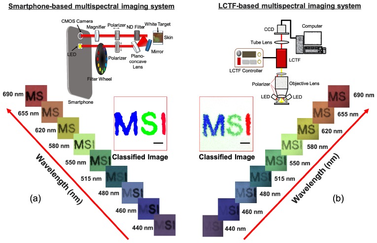
Finally, the outcomes obtained using the smartphone-based system and a multispectral imaging system based on a liquid-crystal tunable filter (LCTF) were compared in order to evaluate the performance of the smartphone-based multispectral imaging system developed here. The LCTF-based multispectral imaging system for the comparison consisted of an objective lens (Olympus, RMS4X), a liquid-crystal tunable filter (Thorlabs, KURIOS-VB1), twelve high-intensity white light-emitting diodes (ITSWELL, IWS-351), and a monochrome CMOS camera (IDS, UI-337XCP-NIR), as shown in Fig. 9(b) (upper). In this system, the selected center wavelengths of filtered light were tuned to be identical to the center wavelengths of band-pass filters installed in the proposed system, and the bandwidths (FWHM) at those wavelengths were set to less than 19 nm. In the LCTF-based multispectral imaging system, the light from LEDs after passing through the polarizer illuminated the target. The light reflected from the target was collected by the objective lens and then passed through the liquid-crystal tunable filter. The filtered light was finally recorded by the CMOS camera [Fig. 9(b), upper]. For a comparison of the performance capabilities, the three letters ‘M’, ‘S’, and ‘I’ were printed on a white paper in blue, green, and green, respectively. Multispectral imaging of the letters was then performed using the systems in order to acquire the letter images at the indicated wavelengths, followed by spectral classification of the images using our developed program. In the letter images at the specified wavelengths, the letters ‘M’ and ‘S’ showed the highest intensity levels at 440 nm and 515 nm, respectively, whereas the letter ‘I’ showed high intensity exceeding 620 nm and thus was not distinguished from the white paper. The spectral classified image obtained using the smartphone-based multispectral imaging system [Fig. 9(a), middle] was comparable to the spectral classified image obtained using the LCTF-based multispectral imaging system [Fig. 9(b), middle].
Fig. 9.
Comparisons between outcomes obtained by multispectral imaging and analysis using the smartphone-based and LCTF-based multispectral imaging systems: (a) multispectral letter images (lower) and a spectral classified image (middle) obtained using the smartphone-based multispectral imaging system (upper) (b) multispectral letter images (lower) and a spectral classified image (middle) obtained using the LCTF-based multispectral imaging system (upper). The scale bar indicates 500 μm.
However, it was found that there are many misclassified pixels in the spectral classified image obtained using the LCTF-based multispectral imaging system. In the ‘M’ classification, the spectral classified image obtained using the LCTF-based multispectral imaging system exhibited ~11.5% misclassification whereas the spectral classified image obtained using the smartphone-based spectral imaging system only exhibited the 0.07% misclassification rate. Also, in the ‘S’ classification, the spectral classified image obtained using the LCTF-based multispectral imaging system exhibited the 0.8% misclassification rate whereas the spectral classified image obtained using the smartphone based-spectral imaging system only exhibited the 0% misclassification rate. However, in the ‘I’ classification, both images did not show any misclassification. Therefore, these results demonstrate that our system offers performance as high as (or even better than) the LCTF-based multispectral imaging system during multispectral imaging and analysis. However, it is important to note that the LCTF-based multispectral imaging system is relatively bulky and expensive and requires a high-intensity illumination source due to its poor light transmission.
2.6 Multispectral imaging and analysis of a nevus region
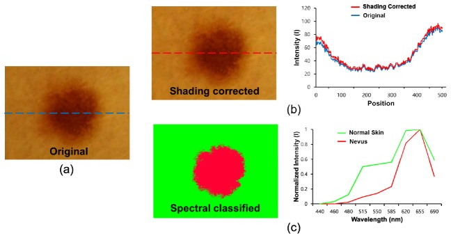
To investigate the potential applications of the smartphone-based multispectral imaging system, multispectral imaging and analysis of a nevus region were performed using the system. In previous reports, it was shown that nevus regions can scarcely be discriminated from instances of melanoma at an early stage. For the multispectral imaging and analysis of the nevus region, nine images of a nevus were acquired at different wavelengths (440, 460, 480, 515, 550, 585, 620, 655, and 690 nm) using the SpectroVision system. The images were then transferred to a server, followed by the spectral classification of the images with reference spectral signatures for the nevus and normal skin. In Fig. 10(a), the original RGB nevus image exhibits shaded regions on the right side of the image, but the corrected image shows that the shaded effects in the image have been reduced, as shown in Fig. 10(b). The intensity profiles along the dotted lines clearly show that the baseline of the intensity profile of the corrected image becomes relatively flat compared to that of the original image [Fig. 10(b), right]. Figure 10(c) shows a spectral classified image (left) and two normalized reference spectral signatures (right) for the nevus and normal skin. The spectral signature for normal skin has higher intensity levels ranging from 460 to 585 nm as compared to those of the spectral signature for the nevus. With the reference spectral signatures, the spectral classified image was obtained using the SpectroVision system [Fig. 10(b), right]. The green color represents normal skin, whereas the red color represents the nevus regions. In the spectral classified image, the nevus regions are clearly separated from the normal regions.
Fig. 10.
Spectral classification of a nevus: (a) original RGB image, (b) a shading-corrected image (left), and a comparison of intensity profiles of the original and corrected image along the dotted lines (right); (c) a conventional spectral classified image (left) and normalized reference spectral signatures for normal skin and a nevus (right) are shown.
2.7 Ratiometric multispectral imaging and analysis to monitor acne regions
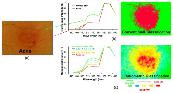
For an investigation of another potential application of the system developed as a mobile skin-diagnosis device, it was applied to monitor acne regions quantitatively after a ratiometric spectral analysis technique was implemented into the system. Figures 11(b) and 11(c) illustrate the conventional and ratiometric spectral classified images. In the conventional classified image, the red color indicates the acne regions, whereas the green color indicates the normal skin regions. In contrast, Fig. 11(c) presents a ratiometric spectral classified image and the corresponding spectral signature. The red and green colors represent severe acne and normal skin, respectively. The cyan, yellow, orange colors represent different levels of severity of the acne regions with respect to the normal regions. These results demonstrate that ratiometric spectral imaging and analysis allowed a better quantitative diagnosis of acne regions, which suggest the potential of this system for quantitative mobile skin care and management. This technique may be applied to monitor the treatment efficacy of drugs applied to acne regions with high levels of quantification.
Fig. 11.
Ratiometric spectral imaging and analysis of acne regions: (a) original RGB image, (b) spectral signatures for normal skin and acne (left), and conventional (left) spectral classified images (right) of acne regions; (c) (b) ratiometric spectral signatures for normal skin and acne (left) and a ratiometric spectral classified image (right) of acne regions (green: 1 x normal skin + 0 x acne, cyan: 0.75 x normal skin + 0.25 x acne, yellow: 0.5 x normal skin + 0.5 x acne, orange: 0.25 x normal skin + 0.75 x acne, and red: 0 x normal skin + 1 x acne). The arrow direction indicates the severity of the acne regions with respect to the normal skin.
3. Discussion
Smartphone-based multispectral imaging and analysis has been investigated for the mobile diagnosis and management of skin lesions. The smartphone-based multispectral imaging system utilized for mobile spectral imaging and analysis here consists of a multispectral imaging system, a smartphone, an interface circuit, and spectral classification techniques. In this study, it was shown that the system allows one to obtain ten images within a wavelength range of 440 – 690 nm (an image cube) with one white-light image. Therefore, the system can be used to obtain a spectral signature at every image pixel in the regions of interest. For spectral classification, the image cube was transferred to a server through WiFi or LTE communication rather than performing spectral classification on the smartphone, as the computing power of the smartphone was not sufficient for the spectral classification of images given the long processing time (over 30 s). In contrast, it was found that the computation time for spectral classification by the server was less than 3 s. In the system, the wavelength range for multispectral imaging was mainly determined by the spectral characteristics of the smartphone LED. Hence, we established a wavelength range of 440 – 690 nm for spectral imaging. In order to achieve a broader spectral range for spectral imaging, the use of an LED with a broader spectral bandwidth may be needed.
Previously, various types of multispectral imaging systems with different approaches for the selection of light wavelengths, such as wavelength-scan methods, spatial-scan methods, and time-scan methods, were developed [30]. In the system devised here, the wavelength-scan method with a set of diced linear variable filters (also known as the band sequential method) was chosen because this method is fairly simple and well suited for the miniaturization of the multispectral imaging system, which must be attached to a smartphone. Moreover, the system does not require additional sophisticated optical components or detectors, such as interferometers. Therefore, the system can be used to make the overall setup simpler and smaller. However, the wavelength-scan method with a set of filters requires mechanical exchanges of the filters to select the desired wavelengths of light, thus resulting in relatively slow wavelength switching compared to that by other electrical switching devices, such as acousto-optical tunable filters (AOTFs) and liquid-crystal tunable filters (LCTFs) [2]. Therefore, to reduce the image acquisition time for multi-spectral imaging and analysis, a new wavelength-selection method without mechanical scanning must be developed for the smartphone-based spectral imaging system.
For an examination of skin lesions in detail, a doublet lens was placed between the smartphone camera lens and the polarizer, as shown in Fig. 2. The magnification was found to be 10x. The image plane formed by the combination of the doublet lens and the smartphone camera lens was located 24 mm from the camera lens. In this system, the LED source was located next to the camera lens for illumination. The distance between the LED and the camera lens was 9.9 mm. Thus, non-uniform illumination on skin lesions occurred due to the short-distance illumination caused by the short focal plane under the configuration of the optical components. To reduce the non-uniform illumination, a plano-concave lens was placed and tilted toward the skin lesions and further shading correction of the images was performed. As shown in Fig. 10, it was found that the shading effects on the images due to non-uniform illumination were reduced after shading correction.
In the performance evaluation of the smartphone-based multispectral imaging system, we clearly showed that the system was capable of at least resolving the spatial frequency of 51 cycles/mm in the vertical and horizontal directions (Fig. 7). This approximately corresponds to an optical resolution of 6 pixels (~18 μm). In a previous report, a multimode dermoscope based on hyperspectral imaging for skin analysis offered an optical resolution of ~300 μm [31]. Here it was found that the smartphone-based multispectral imaging system offered a better optical resolution than the system described in the report. Moreover, the smartphone-based multispectral imaging system allowed one to obtain relatively flat spectral signatures of a white target approximating that of a conventional spectrometer and enabled the production of an accurate spectral signature for the same target with high reproducibility. The variations of spectral signatures were less than 2.3% under the fixed white-balance setting, which represents the limitation of our system when used to discriminate between two different specimens through a comparison of the associated spectral signatures. In Fig. 8, the offsets of spectral signatures of the spectrometer and smartphone system differ for the following reasons: during the acquisition of the spectral signatures of the white target using the smartphone system, the images of the white target obtained at different wavelengths were multiplied by the associated weighting factors predefined through calibration procedures. During the calibration, the maximum intensity among the average intensities of 8-bit gray-scale images at different wavelengths was ~150. The average intensities at different wavelengths were then multiplied by the associated weighting factors to make the average intensities 150. Therefore, the offset of the calibrated spectral signatures of the white target obtained using the smartphone system became ~150. In contrast, the spectral signature of the white target obtained using the spectrometer was ~100 because the system calibrated with the white target offered such an offset of the spectral signature of a white target. This resulted in the different offsets between the spectrometer and the smartphone system. Finally, the performance of the smartphone-based multispectral imaging system developed here was compared to that of a LCTF-based multispectral imaging system. Both systems provided similar spectral classification outcomes. However, as shown in Fig. 9(b), a few misclassified pixels (green-colored pixels) at the white paper regions were found in the classified image obtained using the LCTF-based multispectral imaging system, although the LCTF-based multispectral imaging system utilized twelve white light LEDs for the illumination of a target. Note that the smartphone-based multispectral imaging system utilized one white light LED but could provide a better spectral classified outcome than the LCTF-based multispectral imaging system. These results suggest that the smartphone-based multispectral imaging system offers excellent performance for multispectral imaging and analysis compared to the LCTF-based multispectral imaging system.
For an examination of the potential applications of our system, the multispectral imaging and analysis of a nevus was performed, as shown in Fig. 10. In the figure, the nevus regions are clearly delineated from the normal regions by means of spectral classification. In earlier work, nevus regions were found to be fairly similar to melanoma regions at an early stage; moreover, it was found to be very difficult to discriminate between the two types using a conventional dermoscope [8]. The system developed here may be applied to discriminate between these two types of regions with high accuracy and sensitivity ubiquitously if an advanced quantitative analysis method can be implemented in the system and if it is optimized for the detection of melanoma regions by, for instance, including optimized bandpass filters. Moreover, ratiometric spectral imaging and analysis was employed here to achieve more quantitative discrimination between acne and normal skin regions. In previous research, ratiometric spectral imaging and analysis were shown to have great potential to detect diseased regions through a quantitative analysis of target molecules. As shown in the previous study, the ratiometric spectral imaging and analysis technique here allowed the quantitative measurement of the spectral distance between acne and normal skin regions to be performed. Therefore, during the examination of acne regions, the level of the severity of the acne regions with respect to the normal skin was precisely quantified, thus demonstrating the potential of this method for quantitative mobile skin care and diagnosis.
4. Conclusion
In this study, smartphone-based multispectral imaging and analysis using the developed system was shown to be very useful for mobile skin diagnosis and quantitative management. We built a mobile multispectral imaging system which can be attached to a smartphone. It allows the multispectral imaging and analysis of skin lesions using a smartphone and thus can obtain spectral signatures for skin lesions, enabling the mobile pre-diagnosis and management of diseased regions with high quantification. In particular, with this system, a quantitative analysis of nevus regions was achieved. Moreover, it is capable of quantitatively monitoring acne lesions by means of ratiometric spectral imaging and analysis and offers high portability and quantification of results. For the early detection of skin diseases, patients who exhibit symptoms of diseases must visit clinics frequently; moreover, multiple medical tests should be conducted to diagnose skin lesions with high accuracy. The system developed here would be highly useful for the early-/pre-detection and the quantitative/continuous monitoring of skin diseases with a low cost at home for such patients. Therefore, the results shown in this study demonstrate that smartphone-based multispectral imaging and analysis has great potential as a mobile-healthcare device to diagnose and manage skin lesions. It may also be applicable to the detection of other diseased regions, such as cervical tumors and melanoma, in ubiquitous environments.
Acknowledgments
This work was supported by grants from the National Research Foundation of Korea (NRF) (NRF-2014R1A1A2054934 and NRF-2014M3A9D7070668) for J.Y. Hwang at DGIST.
References and links
- 1.Farkas D. L., Baxter G., DeBiasio R. L., Gough A., Nederlof M. A., Pane D., Pane J., Patek D. R., Ryan K. W., Taylor D. L., “Multimode light microscopy and the dynamics of molecules, cells, and tissues,” Annu. Rev. Physiol. 55(1), 785–817 (1993). 10.1146/annurev.ph.55.030193.004033 [DOI] [PubMed] [Google Scholar]
- 2.Li Q., He X., Wang Y., Liu H., Xu D., Guo F., “Review of spectral imaging technology in biomedical engineering: achievements and challenges,” J. Biomed. Opt. 18(10), 100901 (2013). 10.1117/1.JBO.18.10.100901 [DOI] [PubMed] [Google Scholar]
- 3.Mazzer P. Y., Barbieri C. H., Mazzer N., Fazan V. P., “Morphologic and morphometric evaluation of experimental acute crush injuries of the sciatic nerve of rats,” J. Neurosci. Methods 173(2), 249–258 (2008). 10.1016/j.jneumeth.2008.06.019 [DOI] [PubMed] [Google Scholar]
- 4.Salzer R.ebrary Inc., “Biomedical imaging principles and applications,” (John Wiley & Sons, Hoboken, 2012), pp. xix, 423 p. [Google Scholar]
- 5.Nakamura M., Nishikawa J., Goto A., Nishimura J., Hashimoto S., Okamoto T., Sakaida I., “Usefulness of ultraslim endoscopy with flexible spectral imaging color enhancement for detection of gastric neoplasm: a preliminary study,” J. Gastrointest. Cancer 44(3), 325–328 (2013). 10.1007/s12029-013-9500-z [DOI] [PubMed] [Google Scholar]
- 6.Ramanujan V. K., Ren S., Park S., Farkas D. L., “Non-invasive, Contrast-enhanced Spectral Imaging of Breast Cancer Signatures in Preclinical Animal Models In vivo,” J. Cell Sci. Ther. 1(102), 1 (2010). [DOI] [PMC free article] [PubMed] [Google Scholar]
- 7.Farkas D. L., Becker D., “Applications of spectral imaging: detection and analysis of human melanoma and its precursors,” Pigment Cell Res. 14(1), 2–8 (2001). 10.1034/j.1600-0749.2001.140102.x [DOI] [PubMed] [Google Scholar]
- 8.Elbaum M., Kopf A. W., Rabinovitz H. S., Langley R. G., Kamino H., Mihm M. C., Jr, Sober A. J., Peck G. L., Bogdan A., Gutkowicz-Krusin D., Greenebaum M., Keem S., Oliviero M., Wang S., “Automatic differentiation of melanoma from melanocytic nevi with multispectral digital dermoscopy: a feasibility study,” J. Am. Acad. Dermatol. 44(2), 207–218 (2001). 10.1067/mjd.2001.110395 [DOI] [PubMed] [Google Scholar]
- 9.Fujii H., Yanagisawa T., Mitsui M., Murakami Y., Yamaguchi M., Ohyama N., Abe T., Yokoi I., Matsuoka Y., Kubota Y., “Extraction of acne lesion in acne patients from multispectral images,” Conf. Proc. IEEE Eng. Med. Biol. Soc. 2008, 4078–4081 (2008). [DOI] [PubMed] [Google Scholar]
- 10.Afromowitz M. A., Callis J. B., Heimbach D. M., DeSoto L. A., Norton M. K., “Multispectral imaging of burn wounds: a new clinical instrument for evaluating burn depth,” IEEE Trans. Biomed. Eng. 35(10), 842–850 (1988). 10.1109/10.7291 [DOI] [PubMed] [Google Scholar]
- 11.Stamatas G. N., Southall M., Kollias N., “In vivo monitoring of cutaneous edema using spectral imaging in the visible and near infrared,” J. Invest. Dermatol. 126(8), 1753–1760 (2006). 10.1038/sj.jid.5700329 [DOI] [PubMed] [Google Scholar]
- 12.Kapsokalyvas D., Cicchi R., Bruscino N., Alfieri D., Prignano F., Massi D., Lotti T., Pavone F. S., “In-vivo imaging of psoriatic lesions with polarization multispectral dermoscopy and multiphoton microscopy,” Biomed. Opt. Express 5(7), 2405–2419 (2014). 10.1364/BOE.5.002405 [DOI] [PMC free article] [PubMed] [Google Scholar]
- 13.Jung Y., Kim J., Awofeso O., Kim H., Regnier F., Bae E., “Smartphone-based colorimetric analysis for detection of saliva alcohol concentration,” Appl. Opt. 54(31), 9183–9189 (2015). 10.1364/AO.54.009183 [DOI] [PubMed] [Google Scholar]
- 14.Gallegos D., Long K. D., Yu H., Clark P. P., Lin Y., George S., Nath P., Cunningham B. T., “Label-free biodetection using a smartphone,” Lab Chip 13(11), 2124–2132 (2013). 10.1039/c3lc40991k [DOI] [PubMed] [Google Scholar]
- 15.Yetisen A. K., Martinez-Hurtado J. L., Garcia-Melendrez A., Vasconcellos F. D., Lowe C. R., “A smartphone algorithm with inter-phone repeatability for the analysis of colorimetric tests,” Sens. Actuators B Chem. 196, 156–160 (2014). 10.1016/j.snb.2014.01.077 [DOI] [Google Scholar]
- 16.Do T. T., Zhou Y., Zheng H., Cheung N. M., Koh D., “Early melanoma diagnosis with mobile imaging,” Conf. Proc. IEEE Eng. Med. Biol. Soc. 2014, 6752–6757 (2014). [DOI] [PubMed] [Google Scholar]
- 17.Wadhawan T., Situ N., Rui H., Lancaster K., Yuan X., Zouridakis G., “Implementation of the 7-point checklist for melanoma detection on smart handheld devices,” Conf. Proc. IEEE Eng. Med. Biol. Soc. 2011, 3180–3183 (2011). [DOI] [PMC free article] [PubMed] [Google Scholar]
- 18.Society A. C., “Cancer Facts and Figures 2015,” (2015).
- 19.Buys L. M., “Treatment options for atopic dermatitis,” Am. Fam. Physician 75(4), 523–528 (2007). [PubMed] [Google Scholar]
- 20.Schäkel K., Döbel T., Bosselmann I., “Future treatment options for atopic dermatitis - small molecules and beyond,” J. Dermatol. Sci. 73(2), 91–100 (2014). 10.1016/j.jdermsci.2013.11.009 [DOI] [PubMed] [Google Scholar]
- 21.Mease P. J., Armstrong A. W., “Managing patients with psoriatic disease: the diagnosis and pharmacologic treatment of psoriatic arthritis in patients with psoriasis,” Drugs 74(4), 423–441 (2014). 10.1007/s40265-014-0191-y [DOI] [PMC free article] [PubMed] [Google Scholar]
- 22.Friedman R. J., Rigel D. S., Kopf A. W., “Early detection of malignant melanoma: the role of physician examination and self-examination of the skin,” CA Cancer J. Clin. 35(3), 130–151 (1985). 10.3322/canjclin.35.3.130 [DOI] [PubMed] [Google Scholar]
- 23.Wadhawan T., Situ N., Lancaster K., Yuan X., Zouridakis G., “SkinScan©: a portable library for melanoma detection on handheld devices,” Proc. IEEE Int. Symp. Biomed. Imaging 2011, 133–136 (2011). [DOI] [PMC free article] [PubMed] [Google Scholar]
- 24.Tuan Vo-Dinh B. C. P. K., “Development of a multi-spectral imaging system for medical applications,” J. Phys. D Appl. Phys. 36, 302 (2003). [Google Scholar]
- 25.Song J. H., Kim C., Yoo Y., “Vein visualization using a smart phone with multispectral Wiener estimation for point-of-care applications,” IEEE J. Biomed. Health Inform. 19(2), 773–778 (2015). 10.1109/JBHI.2014.2313145 [DOI] [PubMed] [Google Scholar]
- 26.Groner W., Winkelman J. W., Harris A. G., Ince C., Bouma G. J., Messmer K., Nadeau R. G., “Orthogonal polarization spectral imaging: a new method for study of the microcirculation,” Nat. Med. 5(10), 1209–1212 (1999). 10.1038/13529 [DOI] [PubMed] [Google Scholar]
- 27.Laetitia Abel-Tiberini F. L., Marchand G., Luc Roussel G. A. A. M. L., “Manufacturing of linear variable filters with straight iso-thickness lines,” Proc SPIE 5963, 59630B (2005) [Google Scholar]
- 28.Rafael R. E. W., Gonzalez C., Digital Image Processing, 3rd ed. (Springer, 2008). [Google Scholar]
- 29.Chang C.-I., Hyperspectral Imaging: Techniques for Spectral Detection and Classification (Springer Science & Business Media, 2003). [Google Scholar]
- 30.Garini Y., Young I. T., McNamara G., “Spectral imaging: principles and applications,” Cytometry A 69(8), 735–747 (2006). 10.1002/cyto.a.20311 [DOI] [PubMed] [Google Scholar]
- 31.Vasefi F., MacKinnon N., Saager R. B., Durkin A. J., Chave R., Lindsley E. H., Farkas D. L., “Polarization-sensitive hyperspectral imaging in vivo: a multimode dermoscope for skin analysis,” Sci. Rep. 4, 4924 (2014). 10.1038/srep04924 [DOI] [PMC free article] [PubMed] [Google Scholar]


