Abstract
This paper presents a miniature wrist that can be integrated into needle-sized surgical instruments. The wrist consists of a nitinol tube with asymmetric cutouts that is actuated by a single tendon to provide high distal curvature. We derive and experimentally validate kinematic and static models for the wrist and describe several prototype wrists, illustrating the straightforward fabrication and scalability of the design. We experimentally investigate fatigue life, the concept of tip-first bending, and practical use of the wrist with a concentric tube robot in an endonasal surgical scenario.
1. Introduction
Minimally invasive surgery is constantly being redefined by surgeons and engineers as surgical devices continue to decrease in size. With smaller devices come benefits such as reduced scarring and patient pain. Needle-sized devices have even been used to perform near scarless procedures [1], and they also present exciting opportunities for use in the pediatric population [2]. However, as the diameter of these devices decreases, it becomes increasingly more difficult to create dexterous surgical instruments. Consequently, existing needle-sized devices have limited dexterity and provide a limited number of degrees-of-freedom, reducing their potential impact. The goal of the wrist design presented in this paper is to provide additional degrees-of-freedom and dexterity to needle-sized surgical tools. The added dexterity and degrees-of-freedom could enhance existing needle-sized instruments used in microlaparoscopy [3], retinal surgery [4], and gynecological procedures [5], while also providing the ability to navigate sharp corners in the anatomy as would be encountered at the skull base [6,7], in the middle ear [8], and in the ankle [9].
There have been a number of different wrist designs presented in the literature, including designs based on traditional mechanical linkages, such as ball joints [10], universal joints [11], cables and pulleys [12–14], lead screws [15,16], serial chains in parallel [17], and flexures [18,19]. These designs range from 2.4 to 15 mm. While it may be possible to downscale each of these designs to some extent, continuum structures are often more easily miniaturized than mechanical linkages.
Multiple forms of continuum wrists and dexterous structures have been designed, including a cable-ring design [20], a rolling variable neutral-line mechanism [21], interlocking fiber designs [22,23], a flexible multibackbone design [24], a compliant rolling-contact design [25], and a flexible tubular nitinol structure [26], among others. One promising design being investigated for endonasal skull base surgery is the multi-actuation mechanism found in Ref. [27] that uses multiple cable routings to create a single steerable device. For a thorough review of joints used in existing bendable surgical instruments; see Ref. [28]. In general, designs with fewer components have shown better scalability, and thus designs that involve selective removal of material from a cylindrical substrate to create flexural elements are appealing.
Manufacturing a region of compliant bending in nitinol tubing has been investigated by several groups. Kutzer et al. created a 6 mm tool for arthroscopy that used rectangular, symmetric cutouts [29]. Wei et al. used triangular cuts that were made in nitinol tube to create a similar manipulator [30]. A 10 mm tool used for endoscopic camera steering was developed by Fischer et al. [31]. Various finite element analyses were undertaken by several groups to aid the design of compliant bending regions in nitinol tubes [32,33]. Catheters with bendable nitinol tips were made by both Haga et al. [34] and Bell et al. [35], and a steerable needle tip was created using a machined nitinol tube by Ryu et al. [36].
In this work, we have created a miniature wrist for needle-sized surgical instruments that is made using asymmetric, rectangular cutouts in a nitinol tube, forming a compliant bending region that is actuated with a single tendon. The wrist can be outfitted with various surgical end effectors for delivering treatment in tight spaces (see Fig. 1). Our wrist most closely resembles the catheter and needle designs of [34–36], but operates by a simpler principle and can bend more tightly. Our wrist is straightforward to manufacture and does not employ the intricate spring cutout design nor hydraulic actuation of the active catheter of Ref. [34]. It is small enough for use on needle-sized devices and does not require a nitinol restoring spring like the active catheter design of Ref. [35]. It is also able to achieve a larger deflection over a smaller radius of curvature compared with the active needle design of Ref. [36]. Our wrist is actuated with a single tendon and can be prototyped using inexpensive manufacturing methods. The design is scalable, and the wrist can easily be integrated into needle-sized surgical tools.
Fig. 1.
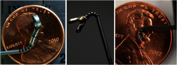
Our wrist can be outfitted with various surgical tools. (a) A curette is attached to the end of the wrist and is affixed to a wire that runs the length of the tube, allowing for rotation of the curette. (b) A gripper is shown attached to the wrist. Note that this gripper was modified from a commercial biopsy tool and is unactuated, but is shown here for illustrative purposes. (c) A laser fiber is deployed through the wrist, illustrating the use of the wrist to aim a laser.
The contributions of this work include validation of the kinematic and statics models for asymmetric cutout wrists, a low-cost manufacturing process, a design method to accomplish tip-first bending of the wrist, and experimental testing of the fatigue life and scalability of the wrist. A preliminary version of some results in this paper can be found in Ref. [37]. In Ref. [37], the kinematic and statics models were derived, and a prototype of the wrist was presented. Additions and enhancements in this archival paper include a new tendon attachment method, a physical demonstration of downscaling the wrist below 0.5 mm, and integration of the wrist with a needle-sized device for endonasal skull base surgery.
2. Design Concept
The wrist is composed of a series of asymmetric cuts made into a nitinol tube (see Fig. 1). The cutouts selectively modify the bending stiffness along the tube tip and enable actuation of the wrist using a single tendon. While symmetric cutouts have been investigated in a variety of devices [29,31,32], the asymmetric cutout geometry offers several advantages over symmetric cutouts (Fig. 2). Using an asymmetric cutout creates a larger moment arm between the tendon and the neutral bending plane, resulting in a lower actuation force. Additionally, actuation of the asymmetric design requires only one tendon, simplifying the tendon routing compared with symmetric designs and improving scalability of the design. Finally, the offset neutral bending plane of the asymmetric design results in a tighter radius of curvature about the centerline of the wrist. While the asymmetric design can only bend in one direction, this is not a major concern so long as the entire device can be rotated.
Fig. 2.

The difference between a symmetric cutout design (left) and an asymmetric design (right) is shown. Note the significantly longer moment arm and reduced tendon force required to actuate the asymmetric design.
Another key feature of our miniature wrist is the ease of integration with needle-sized tools, which is achieved by machining the wrist directly into the needle shaft itself. This prevents the need to affix the wrist onto the end of a millimeter scale tube using adhesives or other mechanical fasteners. Other wrist designs require a connection between the wrist and the tool shaft (see Refs. [15,19], among others), which could ultimately prove problematic at the millimeter scale, where there is often insufficient surface area for adhesives and mechanical fasteners are not available.
3. Kinematic Model
To model the kinematics of the wrist, we first consider a single cutout. We assume that all the bending takes place in the cutout sections, and that these sections deform in circular arcs. In the same manner as Ref. [38], tendon displacement (actuator space) is mapped to arc parameters (configuration space), and then, arc parameters are mapped to task space. The curvature (κ) and arc length (s) we seek are defined in Fig. 3. For a complete derivation of the kinematic model presented below; see Ref. [37].
Fig. 3.
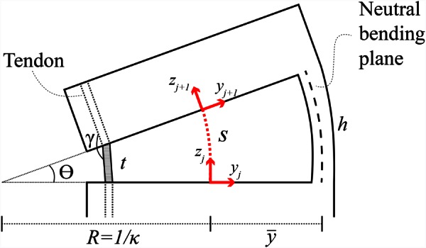
The arc parameters and kinematic values for a single cutout section of the wrist are shown. Cut height is denoted by h, while the chord, t, followed by the tendon is equal to h − Δl, where Δl is the tendon displacement. The angle γ defines the angle the tendon must navigate at each corner and is used to calculate the friction on the tendon in Sec. 4.
In order to find κ and s, the neutral bending plane of the cutout is analyzed. The neutral bending plane is the region of a member that experiences no longitudinal strain during bending. For our wrist, the neutral bending plane, , is assumed to intersect the centroids of the axial cross sections of the cutout portions of the tube (see section view A–A in Fig. 4). The location of , which is valid for cuts that are at least as deep as the outer radius of the tube, is given by
Fig. 4.
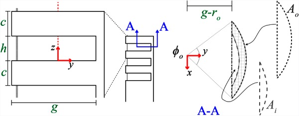
The geometric parameters that can be selected for the wrist design include the uncut section height c, the cutout height h, the cut depth g, and the outer and inner tube radii ro and ri. Section view A–A illustrates the areas Ai and Ao used to calculate the neutral bending plane location.
| (1) |
where areas Ao and Ai are defined in Fig. 4, and are their respective centroids, and and are their central angles
| (2) |
Using , the arc geometry (see Fig. 3), and a small-angle approximation, we can now find the curvature (κ) and arc length (s) for a given tendon displacement (Δl)
| (3) |
A homogeneous transformation between frames j and j + 1 (as defined in Fig. 3) can now be defined using κ and s, as in Ref. [37]. The kinematic transformation from the base to the tip of the wrist is found by repeatedly applying this homogeneous transformation with translations along the zj+1 axis to account for the solid portions of the tube that do not bend. The angle of rotation for each section can be found using κ and s as
| (4) |
and the maximum bending angle and minimum radius of curvature (an approximation of a circular arc passing through the fully deflected wrist; see Fig. 5) are
Fig. 5.
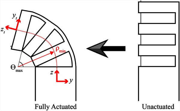
Wrist schematic showing wrist going from unactuated to fully actuated with kinematic frames defined. The maximum bending angle and minimum radius of curvature are both labeled.
| (5) |
where n is the number of cutouts. The wrist kinematics are experimentally validated in Sec. 5.2.
4. Statics Model
In order to model the statics behavior of the wrist, we begin by looking at the strain in a cross section of the cutout portion of the tube in bending, which under the constant curvature assumption varies according to
| (6) |
It is assumed here that the strain is linearly distributed about the neutral bending plane, which allows for a simple computation of the strain energy. The strain energy can then be used with Castigliano's first theorem to obtain the required actuation force. Using a piecewise linear stress–strain curve, a simplified material model for nitinol is used here such that the stress can be expressed as a function of strain as follows:
| (7) |
in which the lower plateau stress σlp corresponds to compression, the upper plateau stress σup corresponds to tension, and E is Young's modulus. The strain energy density is defined here as the area under the stress–strain curve due to the fact that the material deformation is modeled as a one-dimensional stretching and compressing of axial fibers. The total strain energy stored in the wrist is , where the volume Vc is computed using the cross section of uncut tube shown in section view A–A (see Fig. 4) and the cutout height h. Finally, the relationship between tendon force F and rotation θ of the wrist can be found using Castigliano's first theorem
| (8) |
in which L defines the moment arm length, and θ = nsκ. Because of friction, the force applied by the tendon at the tip of the wrist will be less than the actuation force applied on the tendon. In order to account for this frictional loss, a simple model was developed in Ref. [37] that considers the angle γ (see Fig. 3) that the tendon must navigate at a single corner of a cutout section of tube. The force applied by the tendon after passing over a single corner is defined as
| (9) |
where μs is the static friction coefficient, and η < 1 approximates the frictional losses due to the corner. Substituting Eq. (9) into Eq. (8) and using 2n to incorporate the number of corners encountered by the tendon (two corners per cutout) gives an equation relating the tendon force to the wrist angle
| (10) |
For a complete derivation of the statics model; see Ref. [37]. The statics model is experimentally validated in Sec. 5.2.
5. Wrist Fabrication and Testing
For the prototype shown in Fig. 6, a nitinol tube with an outer diameter (OD) of 1.16 mm and an inner diameter (ID) of 0.86 mm was used. The cut depth selected for this prototype was g = 0.965 mm, which corresponds to a maximum outer-fiber strain of approximately 10.4%.1 We selected a cut height of h = 0.51 mm, spacing between cuts of c = 0.51 mm, and n = 5 cuts in order to achieve at least 90 deg of bending. These choices resulted in a wrist with a maximum angle of rotation θmax of 138 deg and a minimum radius of curvature ρmin of 1.42 mm. This wrist was used to validate the kinematic and statics models below, and the wrist was fabricated using a computer numerical control (CNC) milling process.
Fig. 6.
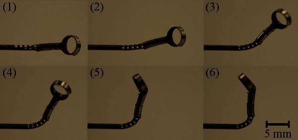
A wrist with a curette at the tip is shown bending from 0 to 90 deg. The sequence order is in the top left of each image. Note that the curette is also being rotated while the wrist is actuated.
To create the wrist using CNC milling, we first make a fixture (Fig. 7) by machining a slot into an aluminum block. The slot width and depth equaled the OD of the nitinol tube. We used a MicroProto Systems MicroMill 2000 CNC mill (a small tabletop CNC that cost approximately $2500 to purchase new) to end mill the slot. The nitinol tube was attached to the fixture using cyanoacrylate adhesive. After creating the fixture, the cutouts in the nitinol tube were machined with the same CNC machine and aluminum titanium nitride coated, two flute, carbide, long flute square end mills. An example of a wrist made with this process can be seen in Fig. 6, and a detailed view of the wrist (after removal of the chips) showing the surface finish can be seen in Fig. 8(a).
Fig. 7.
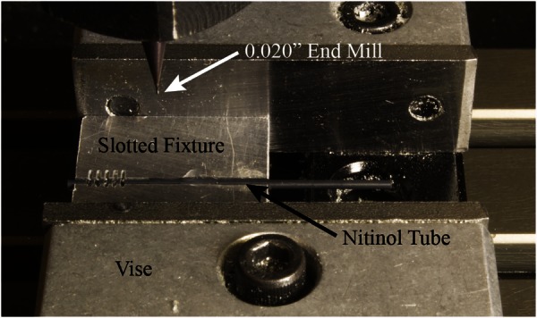
The fixturing setup used for the CNC manufacturing process. The slotted aluminum fixture used to make the wrists, with a nitinol tube glued into the fixture, is held in place by the CNC vise.
Fig. 8.
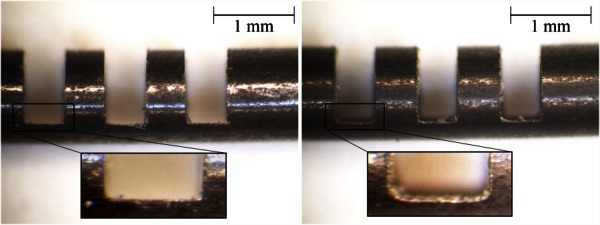
(a) A detailed view of the wrist manufactured using the low-cost CNC milling method. Note the square corners of the cutout made by the square end mill. (b) This wrist was manufactured using wire EDM, and the rounded corners produced by the wire can be seen clearly in the inset.
We also fabricated wrists with wire electrical discharge machining (EDM) that are nearly identical to the CNC wrists, with the main exception being the rounded corners found on the wire EDM wrist cutouts (see Fig. 8(b)). These rounded corners are created by the wire that makes the cutouts, and the radius of these rounded corners is determined by the diameter of EDM wire used. From a basic strength of materials standpoint, the rounded corners should result in lower stress concentrations during actuation in comparison to the square cutout design. However, the heat of the wire EDM process may induce unwanted material characteristics into the wrist. A comparison of the fatigue life for the CNC wrist and the wire EDM wrist is performed in Sec. 5.3.
5.1. Tendon Attachment Methods.
In this work, actuation of the wrist is performed using a single tendon that is made of nitinol. Several tendon attachment methods to rigidly hold the tendon at the tip of the wrist have been explored. First, the tendon was looped around the tip of the wrist and passed through the most distal cutout and back to the base of the wrist [37]. A knot at the end of the tendon wire was also used (see Fig. 13). The method used for the work presented here was to secure the tendon to an end cap that was located at the tip of the wrist (see Fig. 9). The end cap has two holes in it, located at the outer wall of the tube, and the tendon is looped through one hole and back through the other before being terminated in the tip of the wrist. This sharp bend in the tendon plus the friction between the tendon and the end cap rigidly hold the tendon in place. This method helps to reduce the frictional effects on the tendon, ultimately lowering the actuation forces required to articulate the wrist compared with the looping tendon attachment method [37]. It also results in full articulation of the wrist, since none of the cutouts is held open by the looped wire as in Ref. [37]. Finally, the use of a single tendon increases the available space inside the tube for additional wires to actuate an end effector or perform a task.
Fig. 13.
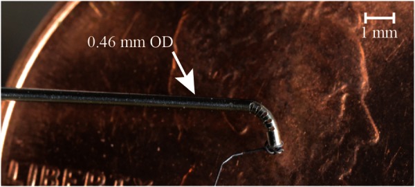
A 0.46 mm OD wrist was made using wire EDM manufacturing and is shown being deflected to approximately 90 deg. It is overlaid here on a penny to provide a sense of scale. For this photograph, the tendon was tied at the end of the wrist since the end caps made for the 1.16 mm wrist prototype were much larger than the 0.46 mm tube.
Fig. 9.
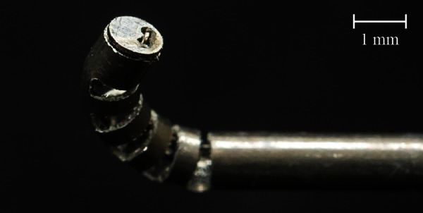
The use of an end cap to attach the tendon to the tip of the wrist is shown. This is the tendon attachment method used in this work.
5.2. Model Validation.
We performed an experiment to explore the accuracy of both the kinematic and statics relationship concurrently. A linear slide (Velmex A2512Q2-S2.5) with 0.01 mm resolution was used to displace the tendon and a force sensor (ATI Nano 17) with 3.125 mN resolution measured the force required to actuate the wrist. The force sensor was mounted to the linear slide, and a collet holder attached to the end of the slide held the wrist. An acrylic plate was mounted to the front of the force sensor, and the tendon was fixed to this plate. The tendon was fixed at the end of the wrist using the end cap. The wrist was deflected by increments of 0.2 mm in tendon displacement, and a microscope with camera attachment captured an image of the deflected wrist at each point (see Fig. 10). Each image was processed manually in order to determine the tip position of the wrist, and comparison with the kinematic model is shown in Fig. 11.
Fig. 10.

The experimental setup used for the kinematics and statics experiment is shown. The wrist was placed directly below a microscope and was held in place using a collet. The tendon was then affixed to a force sensor that was mounted to a linear slide. This allowed for simultaneous collection of force and displacement data.
Fig. 11.
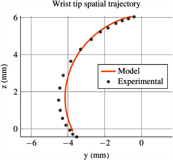
The kinematic model predicted and experimental wrist tip spatial trajectory is shown. The wrist starts at top of the figure and rotates counterclockwise from 0 to 140 deg. These results show that the constant curvature assumption is a reasonable approximation for this geometry, since the wrist tip closely follows the path predicted by the model. It also validates the predicted maximum angle of rotation (138 deg) of the wrist.
The experimental comparison with the statics model is shown in Fig. 12. For the material properties, note that nitinol has an asymmetric stress strain relationship in tension and compression. We assume plateau stresses of σlp = −750 MPa and σup = 500 MPa and a Young's modulus of E = 60 GPa, which fall within ranges reported by the manufacturer and in the literature [39,40]. A coefficient of friction of 0.2 was selected to account for the frictional losses experienced by the tendon when passing over the sharp corners of the cutouts. Using a sensitivity analysis, it was determined that the statics model is most sensitive to the cut depth, with a 1% change in the cut depth resulting in an over 11% change in the required actuation force. Conversely, a 1% change to Young's modulus, the plateau stresses, and the coefficient of friction each resulted in less than a 1% change in the required actuation force. Due to the sensitivity of the model to cut depth and uncertainty in machining tolerances, we fit the cut depth to the model. The fitted cut depth used for the model shown in Fig. 12 is 0.988 mm, which provided the best agreement with the experimental data. Note that the superelastic, nonlinear behavior of the material is clearly captured by the model. The tail at the end of the experimental data likely corresponds to elastic deformation of the portion of the nitinol tube that has transformed into martensite [41], which is not captured by the model.
Fig. 12.
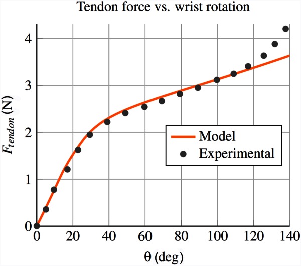
The statics model predicted and experimental results shown here correspond to the tendon force required to actuate the wrist. Note that the model captures the superelastic material behavior, as seen by the change in slope at about θ = 30 deg.
5.3. Fatigue Test.
We performed an experiment to test the fatigue life of the wrist to ensure that the design would be safe for use in surgical applications, where the wrist may be deflected hundreds of times during a procedure. In order to test the fatigue life, we built a motorized setup that would repeatedly actuate the wrist between 0 and 90 deg of bending while simultaneously measuring the actuation force of the tendon in order to determine when the wrist broke. The CNC wrist failed after a total of 8397 cycles, while the wire EDM wrist failed after a total of 8121 cycles. We also fatigue tested the CNC tip-first bending wrist described in Sec. 6.2, which broke after 5858 cycles (note that the cutout geometry of this wrist resulted in a maximum articulation angle of 84 deg). Given that the wrist is intended to be used as a disposable or limited use instrument (similar to the da Vinci tools), the number of cycles to failure is more than adequate to provide a reasonable factor of safety.
6. Scalability and Tip-First Bending
Two benefits of the wrist design presented in this work are the ease with which it can be scaled down due to the limited number of mechanical components and simple actuation scheme, and the ability to selectively alter the stiffness of the device along its length.
6.1. Scalability of Wrist.
By creating the wrist from a single nitinol tube and actuating the wrist with a single tendon, it can theoretically be scaled down to the smallest diameter nitinol tube available (0.178 mm as of this writing [42]). One surgical application for such a small wristed tool is retinal surgery, where the tools used are often less than 0.5 mm in diameter [4]. The physicians often must choose between straight and prebent tools for retinal surgery, and thus, the ability to selectively deflect the tool would be beneficial. To validate the scalability of our design, we manufactured a microwrist (see Fig. 13) from a 0.46 mm OD and 0.28 mm ID nitinol tube using wire EDM machining. The wrist was designed using five cutouts with a 0.33 mm depth of cut, a 0.15 mm cut height, and a 0.15 mm spacing between cuts. We experimentally tested the wrist using the same procedure as described in Sec. 5.2 and compared the motion of the wrist and the force required to actuate it with the kinematic and statics models. The nitinol properties used were the same as in Sec. 5.2, and the depth of cut and coefficient of friction were fit to the data to provide the best agreement. The experimental results can be seen in Figs. 14 and 15 and indicate that our model can be used for varying wrist geometries.
Fig. 14.
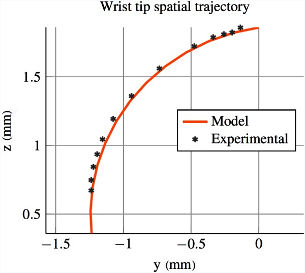
The kinematic model is validated for the submillimetric wrist (0.46 mm OD). These results again indicate that the constant curvature assumption is a reasonable approximation. Close inspection of the wrist at high articulation reveals that the small cutouts are not closing fully, preventing the wrist from reaching the full articulation predicted by the model.
Fig. 15.
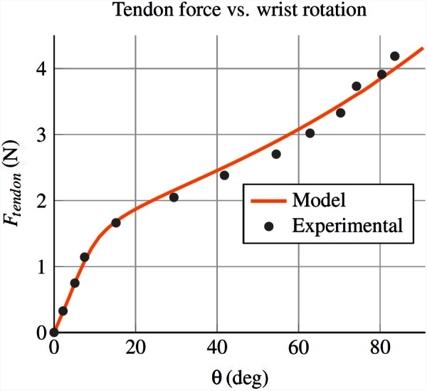
The statics model is also validated for the submillimetric wrist (0.46 mm OD)
6.2. Tip-First Bending of the Wrist.
The ability to bend the tip section first is often desirable when space is limited, as it allows for the tightest radius of curvature for each bending angle. This motion, in which the most distal cutout bends first, followed by the next most distal cutout, and so on, is opposite to the performance of most other tendon-actuated devices, such as steerable catheters. With our wrist, we are able to create tip-first bending by varying the cut height of each cutout such that the most distal cutout has the deepest cut depth and thus the lowest actuation force, and the more proximal cutouts have an increasingly shallower depth of cut.
In order to achieve tip-first bending, we first select the number of cutouts n and cut height h of the cutouts in order to specify the bending radius of the wrist. We then determine the cut depth for the most proximal cutout, as we want this cutout to require the greatest actuation force and bend last. The cut depth of the proximal cutout is chosen such that the uncut region experiences the largest allowable material strain at full bending, given by . We use this equation along with Eqs. (1) and (2) to determine the maximum allowable cut depth for the proximal section, gp. We then select the cut depth of the most distal cutout to be , which corresponds to the lowest allowable actuation force and material strain. Finally, we linearly select the remaining cut depths using , where gi corresponds to the increase in cut depth of each remaining cutout, starting from the most proximal cutout and moving to the most distal cutout.
Tip-first bending can be seen in Fig. 16, where the proximal cutout had a depth of 0.965 mm, the middle cutout had a depth of 0.985 mm, and the distal cutout had a depth of 1.005 mm. The nitinol tube used to make this wrist had an OD of 1.16 mm and an ID of 0.86 mm. The wrist was manufactured using the CNC method described in Sec. 5.
Fig. 16.

This sequence shows the wrist bending from the tip first. In order to accomplish this behavior, the wrist is manufactured such that the most distal cutout has the deepest cut depth, and each sequential cutout is shallower than the cutout before it. This lowers the required actuation force for the most distal cutout and results in the behavior seen here.
7. Wrist Integration With Concentric Tube Robot
One of the most useful features of the wrist is the ease with which it can be integrated into needle-sized surgical devices. One device that could benefit from the addition of such a wrist is the concentric tube robot. Concentric tube robots are needle-sized robotic manipulators that are composed of a series of nested, precurved, superelastic nitinol tubes, often less than 2 mm in diameter, that are often designed for medical applications [43]. They have been investigated for use in prostate removal [44], cardiac applications [45], endonasal skull base surgery [7], and prostate brachytherapy [46]. Because the wrist is made from a nitinol tube (the same material used to make concentric tube robots), the wrist can be directly machined into the inner-most tube of a concentric tube robot. This prevents the need for mechanically joining the wrist and the concentric tube robot and simplifies the overall system. With the use of a single tendon for actuating the wrist, there is little added complexity to the overall concentric tube robot as well. We integrated the wrist into a concentric tube robot presented in Ref. [7], designed for removing pituitary tumors through the nose (see Fig. 17(a)). We then validated the use of the wrist in this procedure by removing gelatin from a phantom skull base model using the same experimental setup as Ref. [7]. An endoscope view of the wrist deflecting to deliver the phantom tumor to the suction device is shown in Fig. 17(b).
Fig. 17.
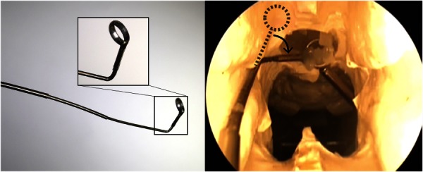
(a) Photograph of our wrist integrated directly into the inner-most tube of a concentric tube robot, with an inset showing a closer view of the wrist and surgical curette attached to the wrist. The diameter of the wrist is 1.16 mm. (b) Here, an endoscope view shows the concentric tube robot with integrated wrist being used to remove a gelatin tumor from a skull base phantom model.
8. Discussion
The aim of the wrist presented in this work is to provide additional degrees-of-freedom and dexterity to needle-diameter surgical tools. One day, such a wrist may even enable surgical approaches that are currently infeasible using existing rigid needlescopic tools. By manufacturing the wrist into the tool shaft itself, integration of the wrist with current rigid needlescopic tools is straightforward. The modeling results predict the behavior of the device and enable design of the wrist for specific surgical tasks. The wrist is straightforward and low-cost to manufacture, and the design is scalable. We have also demonstrated the use of the wrist with a concentric tube robot in a surgical scenario.
Despite the simplicity of the design, there remains a large design space for varying the wrist performance. In this work, we restrict our attention to analyzing rectangular-shaped cutouts, which can be inexpensively manufactured using conventional micromilling techniques. Using a rectangular cutout profile, the designer is able to select the height, depth, and spacing between the cuts, in addition to the number of cutouts and the outer and inner radii of the tube. Using the models and design principles in this work, the user can create a wrist that has desired performance characteristics, such as minimum radius of curvature, maximum bending angle, and maximum tendon actuation force.
The two most important features of the wrist are the tube radii and the depth of cut, as they determine the location of the neutral bending plane, which consequently affects the kinematics, the strain in the portion of nitinol in bending, and the actuation force. The cut height is not as critical as the cut depth at determining the wrist performance, but it does affect the bending radius of the wrist and care must be taken not to make the cut height too large, or else the risk of buckling will increase and the constant curvature assumption will no longer hold. Decreasing the spacing between the cuts decreases the radius of curvature of the wrist, so one should select the smallest spacing that is able to withstand the required actuation forces without breaking. The use of nonuniform cut depths also affects the performance of the wrist, as illustrated in Sec. 6.2, and this capability may prove useful for certain anatomical scenarios or tasks. While it is not possible with the tip-first bending design to prevent some actuation of the proximal sections, the method for tip-first bending described in Sec. 6.2 provides a good approximation for tip-first bending of the wrist.
A potential source of error in the models is the implicit assumption in Eq. (6) that cross sections do not deform during bending, which is a common assumption in beam bending analysis. However, because the wrist will ultimately be controlled under direct visual feedback by the physician, these uncaptured effects can easily be corrected by the human-in-the-loop. This also holds true for any discrepancies between the kinematic model and the experimental data. Furthermore, the fact that the experimental actuation force at extreme rotation angles is higher than the model prediction allows for a simple maximum force limit for safety.
One interesting observation from the fatigue test is that the CNC machined wrist had more cycles to failure than the wire EDM wrist. Given the rounded corners of the wire EDM cutout, one might expect these rounded corners to improve the fatigue life of the wrist, but the opposite was shown here. Additional fatigue tests can help investigate the difference between the number of cycles to failure for the two manufacturing methods. It is also worth noting that the coefficient of friction, an unknown parameter that was selected for agreement between the model and the experimental data, depends on factors such as surface finish and geometry. Future work could investigate additional differences between manufacturing methods, including whether wire EDM manufacturing introduces more heat to the nitinol tube, which may alter the material properties of the nitinol and change the performance of the wrist. Many other avenues exist for future research as well, including optimal wrist design for specific anatomical tasks and the use of nonrectangular cutouts [36] for improved performance of the wrist.
9. Conclusion
As surgeons continue to decrease invasiveness through the use of smaller tools, there is a pressing need to provide them with dexterity at the tip of these needlescopic instruments. In this work, we present a needle-sized, tendon-actuated wrist that is straightforward to manufacture and provides bending in a small radius of curvature, perfect for the tight anatomical spaces where needlescopic tools are often used. A modeling framework is presented for the wrist, and the kinematic and static models are validated using a prototype wrist manufactured in-house on a tabletop CNC. Simple actuation methods are presented for the wrist, and the wrist design and model are shown to be scalable. Tip-first bending of the wrist, a desirable characteristic in tight spaces, is demonstrated by using nonuniform cutouts, and the utility of the needle-sized wrist is illustrated in an anatomical model. The wrist design presented here may one day provide surgeons with the required dexterity to operate in tight anatomical spaces where existing rigid tools cannot be used, thereby decreasing invasiveness and potentially opening the door for exciting new surgical approaches.
Acknowledgment
The authors would like to thank Oliver Commichau for his assistance during experimental testing of the prototype wrists. This work was funded in part by the National Science Foundation (NSF) under CAREER Award No. IIS-1054331 and three Graduate Research Fellowships, in part by the National Institutes of Health (NIH) under Award No. R01 EB017467, and in part by the global collaborative R&D program which is funded by the Ministry of Trade, Industry & Energy (MOTIE, Korea, N0000890).
Footnotes
Note that this is slightly higher than the 8–10% recoverable strain typically quoted for nitinol, but that we have found it to work well in practice, since only a small amount of the material at the very outside edge of the wrist undergoes this strain, and then only at maximum articulation.
Contributor Information
Philip J. Swaney, Department of Mechanical Engineering, , Vanderbilt University, , Nashville, TN 37212 , e-mail: philip.j.swaney@vanderbilt.edu
Peter A. York, Department of Mechanical Engineering, , Harvard University, , Cambridge, MA 02138
Hunter B. Gilbert, Department of Mechanical Engineering, , Vanderbilt University, , Nashville, TN 37212
Jessica Burgner-Kahrs, Associate Professor , Center of Mechatronics, , Leibniz Universität Hannover, , Hannover 30167, Germany.
Robert J. Webster, III, Associate Professor , Department of Mechanical Engineering, , Vanderbilt University, , Nashville, TN 37212 , e-mail: robert.webster@vanderbilt.edu.
References
- [1]. Aurora, A. R. , and Ponsky, J. L. , 2013, “ Future Perspectives on Scarless Surgery: Where We Have Been and Where We are Going,” Scar-Less Surgery, Springer, New York, pp. 341–350. 10.1007/978-1-84800-360-6_27 [DOI] [Google Scholar]
- [2]. Yuan, R.-H. , Lee, W.-J. , and Yu, S.-C. , 1997, “ Mini-Laparoscopic Cholecystectomy: A Cosmetically Better, Almost Scarless Procedure,” J. Laparoendosc. Adv. Surg. Tech., 7(4), pp. 205–211. 10.1089/lap.1997.7.205 [DOI] [PubMed] [Google Scholar]
- [3]. Bonnet, L. , Fett, V. , and Wagner, S. , 1998, “ Microsurgery: Micro-and Mini-Instruments,” Minimally Invasive Ther. Allied Technol., 7(3), pp. 195–200. 10.3109/13645709809152851 [DOI] [Google Scholar]
- [4]. Üneri, A. , Balicki, M. , Handa, J. , Gehlbach, P. , Taylor, R. H. , and Iordachita, I. , 2010, “ New Steady-Hand Eye Robot With Micro-Force Sensing for Vitreoretinal Surgery,” IEEE RAS and EMBS International Conference on Biomedical Robotics and Biomechatronics, Sept. 26–29, pp. 814–819. 10.1109/BIOROB.2010.5625991 [DOI] [PMC free article] [PubMed] [Google Scholar]
- [5]. Asai, S. , Ishimoto, H. , Yabuno, A. , Asada, H. , Mikami, M. , and Yoshimura, Y. , 2016, “ A Novel Modification of Two-Port Laparoscopic Ovarian Cystectomy Using a Needlescopic Instrument: One Surgeon's Initial Experience,” Gynecol. Minimally Invasive Ther., 5(3), pp. 120–123. 10.1016/j.gmit.2015.12.002 [DOI] [Google Scholar]
- [6]. Snyderman, C. H. , Carrau, R. L. , Kassam, A. B. , Zanation, A. , Prevedello, D. , Garnder, P. , and Mintz, A. , 2008, “ Endoscopic Skull Base Surgery: Principles of Endonasal Oncological Surgery,” J. Surg. Oncol., 97(8), pp. 658–664. 10.1002/jso.21020 [DOI] [PubMed] [Google Scholar]
- [7]. Burgner, J. , Rucker, D. C. , Gilbert, H. B. , Swaney, P. J. , Russell, P. T. , Weaver, K. D. , and Webster, R. J. , 2014, “ A Telerobotic System for Transnasal Surgery,” IEEE Trans. Mechatronics, 19(3), pp. 996–1006. 10.1109/TMECH.2013.2265804 [DOI] [PMC free article] [PubMed] [Google Scholar]
- [8]. Badr-el Dine, M. , 2002, “ Value of Ear Endoscopy in Cholesteatoma Surgery,” Otol. Neurotol., 23(5), pp. 631–635. 10.1097/00129492-200209000-00004 [DOI] [PubMed] [Google Scholar]
- [9]. Golanó, P. , Vega, J. , Pérez-Carro, L. , and Götzens, V. , 2006, “ Ankle Anatomy for the Arthroscopist—Part I: The Portals,” Foot Ankle Clin., 11(2), pp. 253–273. 10.1016/j.fcl.2006.03.005 [DOI] [PubMed] [Google Scholar]
- [10]. Berkelman, P. , and Ma, J. , 2009, “ A Compact Modular Teleoperated Robotic System for Laparoscopic Surgery,” Int. J. Rob. Res., 28(9), pp. 1198–1215. 10.1177/0278364909104276 [DOI] [PMC free article] [PubMed] [Google Scholar]
- [11]. Shang, J. , Noonan, D. P. , Payne, C. , Clark, J. , Sodergren, M. H. , Darzi, A. , and Yang, G.-Z. , 2011, “ An Articulated Universal Joint Based Flexible Access Robot for Minimally Invasive Surgery,” IEEE International Conference on Robotics and Automation, May 9–13, pp. 1147–1152. 10.1109/ICRA.2011.5980261 [DOI] [Google Scholar]
- [12]. Shin, W.-H. , and Kwon, D.-S. , 2013, “ Surgical Robot System for Single-Port Surgery With Novel Joint Mechanism,” IEEE Trans. Biomed. Eng., 60(4), pp. 937–944. 10.1109/TBME.2013.2242070 [DOI] [PubMed] [Google Scholar]
- [13]. Zhao, B. , and Nelson, C. A. , 2013, “ Decoupled Cable-Driven Grasper Design Based on Planetary Gear Theory,” J. Med. Devices, 7(2), p. 020918. 10.1115/1.4024329 [DOI] [Google Scholar]
- [14]. Jelínek, F. , Pessers, R. , and Breedveld, P. , 2013, “ Dragonflex–Smart Steerable Laparoscopic Instrument,” J. Med. Devices, 7(2), p. 020911. 10.1115/1.4024319 [DOI] [Google Scholar]
- [15]. Ishii, C. , and Kobayashi, K. , 2007, “ Development of a New Bending Mechanism and Its Application to Robotic Forceps Manipulator,” IEEE International Conference on Robotics and Automation, Apr. 10–14, pp. 238–243. 10.1109/ROBOT.2007.363793 [DOI] [Google Scholar]
- [16]. Hammond, F. , Howe, R. , and Wood, R. , 2013, “ Dexterous High-Precision Robotic Wrist for Micromanipulation,” International Conference on Advanced Robotics, Nov. 25–29, pp. 1–8. 10.1109/ICAR.2013.6766578 [DOI]
- [17]. Hong, M. B. , and Jo, Y.-H. , 2014, “ Design of a Novel 4-DOF Wrist-Type Surgical Instrument With Enhanced Rigidity and Dexterity,” IEEE/ASME Trans. Mechatronics, 19(2), pp. 500–511. 10.1109/TMECH.2013.2245143 [DOI] [Google Scholar]
- [18]. Arata, J. , Saito, Y. , and Fujimoto, H. , 2010, “ Outer Shell Type 2-DOF Bending Manipulator Using Spring-Link Mechanism for Medical Applications,” IEEE International Conference on Robotics and Automation, Anchorage, AL, May 3–8, pp. 1041–1046.http://fileadmin.cs.lth.se/ai/Proceedings/ICRA2010/MainConference/data/papers/0258.pdf [Google Scholar]
- [19]. Sieklicki, W. , Zoppi, M. , and Molfino, R. , 2009, “ Superelastic Compliant Mechanisms for Needlescopic Surgical Wrists,” ASME/IFToMM International Conference on Reconfigurable Mechanisms and Robots, June 22–24, pp. 392–399.http://ieeexplore.ieee.org/document/5173859/ [Google Scholar]
- [20]. Breedveld, P. , 2010, “ Steerable Laparoscopic Cable-Ring Forceps,” J. Med. Devices, 4(2), p. 027518. 10.1115/1.3443169 [DOI] [Google Scholar]
- [21]. He, X. , van Geirt, V. , Gehlbach, P. , Taylor, R. , and Iordachita, I. , 2015, “ IRIS: Integrated Robotic Intraocular Snake,” IEEE International Conference on Robotics and Automation, May 26–30, pp. 1764–1769. 10.1109/ICRA.2015.7139426 [DOI] [PMC free article] [PubMed] [Google Scholar]
- [22]. Frasson, L. , Ko, S. Y. , Turner, A. , Parittotokkaporn, T. , Vincent, J. F. , and Rodriguez y Baena, F. , 2010, “ Sting: A Soft-Tissue Intervention and Neurosurgical Guide to Access Deep Brain Lesions Through Curved Trajectories,” Proc. Inst. Mech. Eng., Part H, 224(6), pp. 775–788. 10.1243/09544119JEIM663 [DOI] [PubMed] [Google Scholar]
- [23]. Moses, M. S. , Kutzer, M. D. M. , Ma, H. , and Armand, M. , 2013, “ A Continuum Manipulator Made of Interlocking Fibers,” IEEE International Conference on Robotics and Automation, May 6–10, pp. 4008–4015. 10.1109/ICRA.2013.6631142 [DOI] [Google Scholar]
- [24]. Simaan, N. , 2005, “ Snake-Like Units Using Flexible Backbones and Actuation Redundancy for Enhanced Miniaturization,” IEEE International Conference on Robotics and Automation, Apr. 18–22, pp. 3012–3017. 10.1109/ROBOT.2005.1570572 [DOI] [Google Scholar]
- [25]. Nai, T. Y. , Herder, J. L. , and Tuijthof, G. J. , 2011, “ Steerable Mechanical Joint for High Load Transmission in Minimally Invasive Instruments,” J. Med. Devices, 5(3), p. 034503. 10.1115/1.4004649 [DOI] [Google Scholar]
- [26]. Peirs, J. , Van Brussel, H. , Reynaerts, D. , and De Gersem, G. , 2002, “ A Flexible Distal Tip With Two Degrees of Freedom for Enhanced Dexterity in Endoscopic Robot Surgery,” 13th Micromechanics Europe Workshop, Sinaia, Romania, Oct. 6–8, pp. 271–274.http://citeseerx.ist.psu.edu/viewdoc/download?doi=10.1.1.557.1729&rep=rep1&type=pdf [Google Scholar]
- [27]. Gerboni, G. , Henselmans, P. W. J. , Arkenbout, E. A. , van Furth, W. R. , and Breedveld, P. , 2015, “ Helixflex: Bioinspired Maneuverable Instrument for Skull Base Surgery,” Bioinspiration Biomimetics, 10(6), p. 066013. 10.1088/1748-3190/10/6/066013 [DOI] [PubMed] [Google Scholar]
- [28]. Jelínek, F. , Arkenbout, E. A. , Henselmans, P. W. J. , Pessers, R. , and Breedveld, P. , 2015, “ Classification of Joints Used in Steerable Instruments for Minimally Invasive Surgery—A Review of the State of the Art,” J. Med. Devices, 9(1), p. 010801. 10.1115/1.4028649 [DOI] [Google Scholar]
- [29]. Kutzer, M. D. M. , Segreti, S. M. , Brown, C. Y. , Armand, M. , Taylor, R. H. , and Mears, S. C. , 2011, “ Design of a New Cable-Driven Manipulator With a Large Open Lumen: Preliminary Applications in the Minimally-Invasive Removal of Osteolysis,” IEEE International Conference on Robotics and Automation, May 9–13, pp. 2913–2920. 10.1109/ICRA.2011.5980285 [DOI] [Google Scholar]
- [30]. Wei, D. , Wenlong, Y. , Dawei, H. , and Zhijiang, D. , 2012, “ Modeling of Flexible Arm With Triangular Notches for Applications in Single Port Access Abdominal Surgery,” IEEE International Conference on Robotics and Biomimetics, Dec. 11–14, pp. 588–593. 10.1109/ROBIO.2012.6491030 [DOI] [Google Scholar]
- [31]. Fischer, H. , Vogel, B. , Pfleging, W. , and Besser, H. , 1999, “ Flexible Distal Tip Made of Nitinol (NiTi) for a Steerable Endoscopic Camera System,” Mater. Sci. Eng. A, 273–275, pp. 780–783. 10.1016/S0921-5093(99)00415-3 [DOI] [Google Scholar]
- [32]. Liu, J. , Hall, B. , Frecker, M. , and Reutzel, E. W. , 2013, “ Compliant Articulation Structure Using Superelastic Nitinol,” Smart Mater. Struct., 22(9), p. 094018. 10.1088/0964-1726/22/9/094018 [DOI] [Google Scholar]
- [33]. Kim, J. , Lee, D. , Kim, K. , Kang, S. , and Cho, K.-J. , 2014, “ Toward a Solution to the Snapping Problem in a Concentric-Tube Continuum Robot: Grooved Tubes With Anisotropy,” IEEE International Conference on Robotics and Automation, May 31–June 7, pp. 5871–5876. 10.1109/ICRA.2014.6907723 [DOI] [Google Scholar]
- [34]. Haga, Y. , Muyari, Y. , Goto, S. , Matsunaga, T. , and Esashi, M. , 2011, “ Development of Minimally Invasive Medical Tools Using Laser Processing on Cylindrical Substrates,” Electr. Eng. Jpn., 176(1), pp. 65–74. 10.1002/eej.21030 [DOI] [Google Scholar]
- [35]. Bell, J. A. , Saikus, C. E. , Ratnayaka, K. , Wu, V. , Sonmez, M. , Faranesh, A. Z. , Colyer, J. H. , Lederman, R. J. , and Kocaturk, O. , 2012, “ A Deflectable Guiding Catheter for Real-Time MRI-Guided Interventions,” J. Magn. Reson. Imaging, 35(4), pp. 908–915. 10.1002/jmri.23520 [DOI] [PMC free article] [PubMed] [Google Scholar]
- [36]. Ryu, S. C. , Renaud, P. , Black, R. , Daniel, B. L. , and Cutkosky, M. R. , 2011, “ Feasibility Study of an Optically Actuated MR-Compatible Active Needle,” IEEE/RSJ International Conference on Intelligent Robots and Systems, pp. 2564–2569. 10.1109/IROS.2011.6094945 [DOI] [PMC free article] [PubMed] [Google Scholar]
- [37]. York, P. A. , Swaney, P. J. , Gilbert, H. B. , and Webster, R. J., III , 2015, “ A Wrist for Needle-Sized Surgical Robots,” IEEE International Conference on Robotics and Automation, May 26–30, pp. 1776–1781. 10.1109/ICRA.2015.7139428 [DOI] [PMC free article] [PubMed] [Google Scholar]
- [38]. Webster, R. J., III , and Jones, B. A. , 2010, “ Design and Kinematic Modeling of Constant Curvature Continuum Robots: A Review,” Int. J. Rob. Res., 29(13), pp. 1661–1683. 10.1177/0278364910368147 [DOI] [Google Scholar]
- [39]. Pelton, A. , DiCello, J. , and Miyazaki, S. , 2000, “ Optimisation of Processing and Properties of Medical Grade Nitinol Wire,” Minimally Invasive Ther. Allied Technol., 9(2), pp. 107–118. 10.3109/13645700009063057 [DOI] [Google Scholar]
- [40]. Reedlunn, B. , Churchill, C. B. , Nelson, E. E. , Shaw, J. A. , and Daly, S. H. , 2014, “ Tension, Compression, and Bending of Superelastic Shape Memory Alloy Tubes,” J. Mech. Phys. Solids, 63, pp. 506–537. 10.1016/j.jmps.2012.12.012 [DOI] [Google Scholar]
- [41]. Tan, G. , and Liu, Y. , 2004, “ Comparative Study of Deformation-Induced Martensite Stabilisation Via Martensite Reorientation and Stress-Induced Martensitic Transformation in NiTi,” Intermetallics, 12(4), pp. 373–381. 10.1016/j.intermet.2003.11.008 [DOI] [Google Scholar]
- [42].Memry Corporation, 2015, “ Nitinol Tube,” Memry Corporation, Bethel, CT, accessed July 24, 2015, http://www.memry.com/products-services/material/tube [Google Scholar]
- [43]. Burgner-Kahrs, J. , Rucker, D. C. , and Choset, H. , 2015, “ Continuum Robots for Medical Applications: A Survey,” IEEE Trans. Rob., 31(6), pp. 1261–1280. 10.1109/TRO.2015.2489500 [DOI] [Google Scholar]
- [44]. Hendrick, R. J. , Herrell, S. D. , and Webster, R. J., III , 2014, “ A Multi-Arm Hand-Held Robotic System for Transurethral Laser Prostate Surgery,” IEEE International Conference on Robotics and Automation, May 31–June 7, pp. 2850–2855. 10.1109/ICRA.2014.6907268 [DOI] [Google Scholar]
- [45]. Gosline, A. H. , Vasilyev, N. V. , Butler, E. J. , Folk, C. , Cohen, A. , Chen, R. , Lang, N. , del Nido, P. J. , and Dupont, P. E. , 2012, “ Percutaneous Intracardiac Beating-Heart Surgery Using Metal MEMS Tissue Approximation Tools,” Int. J. Rob. Res., 31(9), pp. 1081–1093. 10.1177/0278364912443718 [DOI] [PMC free article] [PubMed] [Google Scholar]
- [46]. Torabi, M. , Gupta, R. , and Walsh, C. J. , 2014, “ Compact Robotically Steerable Image-Guided Instrument for Multi-Adjacent-Point (Map) Targeting,” IEEE Trans. Rob., 30(4), pp. 802–815. 10.1109/TRO.2014.2304773 [DOI] [Google Scholar]


