Abstract
Using mobile smart devices to provide urban location-based services (LBS) with sub-meter-level accuracy (around 0.5 m) is a major application field for future global navigation satellite system (GNSS) development. Real-time kinematic (RTK) positioning, which is a widely used GNSS-based positioning approach, can improve the accuracy from about 10–20 m (achieved by the standard positioning services) to about 3–5 cm based on the geodetic receivers. In using the smart devices to achieve positioning with sub-meter-level accuracy, a feasible solution of combining the low-cost GNSS module and the smart device is proposed in this work and a user-side GNSS RTK positioning software was developed from scratch based on the Android platform. Its real-time positioning performance was validated by BeiDou Navigation Satellite System/Global Positioning System (BDS/GPS) combined RTK positioning under the conditions of a static and kinematic (the velocity of the rover was 50–80 km/h) mode in a real urban environment with a SAMSUNG Galaxy A7 smartphone. The results show that the fixed-rates of ambiguity resolution (the proportion of epochs of ambiguities fixed) for BDS/GPS combined RTK in the static and kinematic tests were about 97% and 90%, respectively, and the average positioning accuracies (RMS) were better than 0.15 m (horizontal) and 0.25 m (vertical) for the static test, and 0.30 m (horizontal) and 0.45 m (vertical) for the kinematic test.
Keywords: global navigation satellite system (GNSS), BeiDou navigation satellite system (BDS), real-time kinematic (RTK), smart devices, location-based services (LBS)
1. Introduction
With the development of global navigation satellite systems (GNSSs), the location-based services (LBS) industry has become one of the fastest-growing emerging information industries [1]. Smart devices, which are usually based on Android or iOS platforms, are being widely used due to the booming development of mobile Internet technology and they are playing important roles in LBS. Achieving positioning and navigation with sub-meter-level accuracy on smart devices is an important application field for the future development of GNSSs. Moreover, the multi-GNSS combined positioning, which can significantly improve the positioning availability, continuity and accuracy, has become an inevitable trend in future location-based applications [2,3]. Currently, with the operation of the Chinese BeiDou Navigation Satellite System (BDS) [4] in the Asia-Pacific region, excellent opportunities for BDS/GNSS combined positioning are available for users [2,5,6]. Precise positioning and navigation based on low-cost receivers also becomes possible with the support of multi-constellations [7,8,9,10]. However, the positioning accuracy provided by the commonly used smart devices, such as smartphones with an embedded GNSS chip, is only about 15–20 m through the single-point positioning (SPP) approach [11], and it is very difficult to meet the demands of high-precision LBS, which usually requires sub-meter-level positioning [12,13].
Compared with SPP, the differential positioning approach, which is implemented based on the differential corrections from nearby reference stations, is still one of the commonly used techniques for achieving high-precision and instantaneous positioning in practice. The differential positioning technique can be divided into two categories, i.e., DGNSS (differential GNSS) and RTK (real-time kinematic). The former is usually implemented using the code observables, whereas the latter uses the carrier phase. Previous studies [5,14,15] show that the positioning accuracies of DGNSS and RTK with a geodetic receiver are about 1.0–2.0 m and 0.02–0.05 m, respectively. Due to the high price and large size, the geodetic receivers cannot be directly used in LBS services. Different from the geodetic receivers which can generate the code and carrier phase observables with high precision, the observables from those mass-market navigational receivers generally have low precision [16,17]. As a result, the accuracy of DGNSS with a low-price navigation terminal can only reach about 3.0–5.0 m and RTK positioning is very difficult to achieve [17]. In recent years, several novel PPP (precise point positioning)-RTK positioning methods have been proposed and studied [18,19,20,21,22,23,24]. For implementing PPP-RTK positioning, the un-differenced ambiguities of the carrier phase need to be fixed at a single receiver. This can be achieved by correcting the fractional cycle biases which are estimated based on the observation data from a station network and broadcasted to users as products. However, since the data quality of a low-cost receiver is poorer than that of the commonly used geodetic receiver, the performances of un-differenced integer ambiguity resolution and PPP-RTK positioning in practice still need to be further studied.
In order to further improve the positioning performance of smart devices, an approach for combining the smart device and the low-cost GNSS module which can provide the code and carrier phase observables is proposed in this study to achieve a high-accuracy positioning with the RTK technique, as well as the software of BDS/GNSS RTK positioning installed on the Android platform. The proposed approach is a feasible solution to achieve high-accuracy positioning with such a smart device which cannot provide the observables with high precision. The performances of the proposed approach and developed software were validated by real-time static and kinematic tests in a real urban environment under the BDS and GPS constellations.
This paper is organized as follows: first, the system design scheme and implementation solutions for realizing RTK positioning based on smart devices are described in Section 2; secondly, the experimental results of the performance validation in a real urban environment are given in Section 3; and, finally, the conclusions are drawn and future works are discussed in Section 4.
2. System Design Scheme and Implementation
2.1. System Design Scheme
RTK positioning requires not only the raw observations and satellite ephemeris of the rover, but also the raw observations or the differential corrections from nearby reference stations. The communication link or network for data transmission between the reference station and the rover is also needed in RTK positioning.
It is very easy to collect the required raw observations and ephemeris by a general GNSS receiver, but it is not feasible for most smart devices with an embedded GNSS chip (such as smartphones, etc.) [11,25]. Therefore, obtaining the required observations is a prerequisite for achieving RTK positioning on smart devices. To solve this problem, an effective way is using an external GNSS module (such as u-blox, etc.) to provide the required rover observations and ephemeris and collecting these data in real-time using those smart devices with the built-in Bluetooth modules via the Bluetooth protocol. With respect to the data transmission from the reference station to the rover, specialized equipment, such as a radio frequency station, is generally used in traditional RTK applications. However, it is not well-suited for mass-market LBS applications. Since smart devices are usually equipped with Internet-accessing capabilities, the communication problem can be easily solved by accessing the 3G/4G cellular or Wi-Fi (if available) network.
The main integration idea for smart device–supported RTK positioning is making the most of the wireless communication ability, the computing capability, and the extensive-usage advantage of those mass-market smart devices. In this contribution, a real-time RTK service system was designed for precise LBS, and the precise LBS services can be further extended (e.g., the lane-level navigation) once the user has the ability to obtain high-accuracy positioning results. This system mainly consists of a reference station, a data processing center (DPC), and a user part, as shown in Figure 1.
Figure 1.
Framework of an RTK service system based on smart devices.
The reference station equipped with a high-performance geodetic receiver is for collecting the raw GNSS observations, including the measurements of the code and carrier phase and the satellites’ ephemeris, etc., and sending them to the DPC in real time through a data communication link, such as the Internet used in our system. The sampling rate of the raw observations at the reference station is 1 Hz.
The functions of the DPC consist of receiving the data streams from the reference station in real time, calculating the differential correction information and broadcasting them to users through a wireless network. In our system, the differential corrections are applied instead of sending the raw observations for reducing the amount of data to be transmitted and the cost of communication. They are calculated by the DPC with a specific algorithm and broadcasted to users through the user datagram protocol (UDP).
The user part includes an external GNSS module and a smart device, e.g., a smartphone. The main work of the user part is providing the real-time high-accuracy results by RTK positioning. The smart device collects the observation and ephemeris data (in binary) provided by the external GNSS device through its built-in Bluetooth module. Meanwhile, it establishes a communication connection with the DPC and receives the differential corrections via a 3G/4G cellular or Wi-Fi (if available) network using the UDP protocol. Thus, the RTK positioning can be achieved with the raw observations, ephemeris, and differential corrections. If the network communication with the DPC is lost, the single-point positioning solutions will be given with only the raw observations being used, and if the Bluetooth connection with the GNSS module is temporarily lost, the self-positioning results of the smart device (from the embedded GNSS chip) will be returned to the user.
With respect to the smart devices, there are no other special requirements for them in this system. The basic requirements are that they: (1) run Android OS 4.1 or above; (2) have a built-in Bluetooth module (version 4.0 will be better) for collecting the raw data stream from the external GNSS module; and (3) have Internet accessibility (cellular or Wi-Fi networks are both okay) for receiving the differential correction data.
2.2. Mathematical Model
The double-differenced (DD) observation model is widely used in RTK positioning. It can eliminate the satellite and receiver clock errors and significantly mitigate the atmospheric (ionosphere and troposphere) delay errors under the condition of a short baseline [14,26], especially when the ionosphere is quiet [27]; therefore, it is beneficial for ambiguity resolution. The basic non-linear code and carrier phase observation equation of the un-differenced (UD) model on one frequency is given in Equation (1):
| (1) |
where P is the code observation (meters); φ is the carrier phase observation (cycle); j and r represent the satellite and receiver, respectively; ρ is the geometric distance from the satellite to the receiver; c is the velocity of light; dtj and dtr denote the clock error of the satellite j and the receiver r, respectively; I and T are the ionospheric and tropospheric delays, respectively; λ is the wavelength; N is the phase ambiguity (cycle); ε and ζ represent the code and carrier phase observation noise, including some unmodeled errors, e.g., multipath, respectively.
At the reference station r, the geometric distance from the satellite j to the receiver antenna can be derived as Equation (2):
| (2) |
where, [Xj, Yj, Zj] denotes the position of satellite j which can be calculated from the broadcast ephemeris; [Xr, Yr, Zr] denotes the position of reference station r which is usually known. Thus, the differential correction of code and carrier phase can be calculated by Equation (3) and they will be broadcasted to users by the communication link established in the real-time RTK service system:
| (3) |
Hence, for the user u, the corrected code and carrier phase can be calculated in Equation (4) which is the single-differenced (SD) model between two receivers:
| (4) |
Then, choosing the highest-elevation satellite (referred to as k) as the reference satellite to form the double-differenced (DD) model, as shown in Equation (5):
| (5) |
For the short-baseline conditions, the following approximations can be accepted:
| (6) |
Thus, from Equations (5) and (6) it can be seen that the satellite and receiver clock errors are eliminated and the atmospheric (ionosphere and troposphere) delay errors are mitigated significantly under the condition of a short baseline.
In addition, the stochastic model is essential for obtaining high-precision positioning results and the elevation-dependent weighting model [28] is adopted in the proposed approach, shown in Equation (7):
| (7) |
where is the variance of the un-differenced observation; r represents the receiver; j represents the visible satellite; a and b are the constant error factors which are usually chosen empirically or calculated with the prior information of the observed data; el denotes the elevation angle from the receiver to the observed satellite; and f(el) = 1/sin(el) [28] is an elevation-related function.
2.3. Ambiguity Resolution and Validation
Compared with the positioning results derived from the float or incorrectly fixed ambiguities, the positioning accuracy can be improved when the ambiguities can be correctly fixed. In the proposed approach, the Least-squares AMBiguity Decorrelation Adjustment (LAMBDA) method [29,30] was applied for ambiguity resolution to obtain the integer ambiguities (fixed solution) after obtaining the float estimates of the ambiguities. For validating the integer ambiguity estimates, there are two widely used methods, i.e., the traditional ratio test (RT) and the fixed failure-rate ratio test (FF-RT) [31,32,33,34,35,36]. The traditional RT approach adopts a fixed critical threshold which is usually chosen from experience, e.g., 1.5, 2, or 3 [26,37]. The threshold with an improper selection would largely affect the positioning results. A high threshold may lead to a large probability of “false alarms” (i.e., refusing the correctly fixed integer ambiguities), while a low threshold may result in a higher probability of “missed detection” (i.e., accepting the incorrectly fixed integer ambiguities). The FF-RT approach is a detection criteria based on a fixed failure rate (Pf) of which the critical threshold is determined according to the user-defined acceptable failure rate, the number of ambiguities, and the conditional variance of the ambiguities. Section 2.4.2 shows a comparison of the effects on the performance of RTK positioning based on the methods of RT and FF-RT as an example. In this contribution, the FF-RT method was used for validating the fixed ambiguities and the acceptable failure rate was set to Pf = 0.01.
2.4. Latency Time of the Differential Corrections
In the RTK system, the differential corrections calculated from the observations of the reference station are usually sent to users through a wireless communication link. As a result, it is impossible to avoid the latency time in receiving the corrections and even the temporary interruption due to the failure of the network connection. Since the latency time and temporary interruption are generally dependent on the performance of the wireless link [38], there are two problems that need to be considered: (1) the length of the latency time of the differential corrections; and (2) the effect of the latency time (includes the temporary interruption) on the ambiguity resolution and positioning accuracy. The above two problems are analyzed by the following tests, respectively.
2.4.1. Analysis of the Latency Time of the Differential Corrections
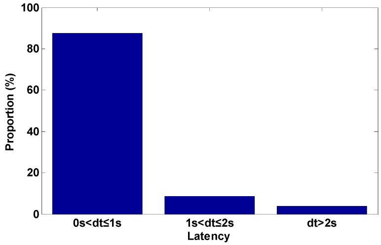
This test included two steps. First, the time of the DPC center server and the user-side smart device were synchronized and maintained through the network time protocol (NTP). Secondly, the DPC server sent the correction packets to the user with a transmission timestamp and the user marked a reception timestamp for the differential correction packets received. After a continuous test for about 12 h with a Wi-Fi network connection, the length of the latency time can be obtained by calculating the time differences between the transmission time and the reception time.
Figure 2 shows the statistical result of the length of the latency time of the corrections. We can find that the latency time of the differential corrections in the communication was almost within two seconds. It should be noted that the corresponding latency time of differential corrections may be slightly different, depending on the performance of the communication networks accessed in the practical application.
Figure 2.
The statistical results of the length of the latency time of the corrections.
2.4.2. Analysis of the Effect of Latency Time on RTK Positioning
To reduce the effect of the latency time of the differential corrections on a user’s positioning performance, the variation rate of the code and carrier phase correction is also included in the differential correction information [39]. However, with the increase of the latency time of the corrections, especially the temporary interruption of communication, the RTK positioning performance will gradually become worse. In order to analyze the effect of the latency time on the performance of ambiguity resolution and positioning accuracy with RTK, a test including three types of latency time of the differential corrections, i.e., 0 s, 5 s, and 10 s, was carried out by post-processing RTK positioning. Moreover, the difference between the traditional RT and FF-RT was also tested with the consideration of different latency times of the differential corrections. The data used in this test was collected in static mode under the condition of a short baseline by two GPS/BDS receivers with a testing period of about 15 h, and the distance between the reference station and the rover was about 5 km. The test results are shown in Table 1.
Table 1.
The performances of RTK positioning with different latency times of the differential corrections.
| Validation Approaches | Latency Time of Corrections (s) | Ambiguity Fixed-Rate (%) | RMS Error (cm) | ||
|---|---|---|---|---|---|
| Fixed Solutions | Unfixed Solutions | Whole Solutions | |||
| Traditional RT with fixed threshold (=2.0) | 0 | 96.9 | 1.5 | 40.7 | 9.0 |
| 5 | 95.5 | 1.7 | 46.7 | 10.2 | |
| 10 | 91.0 | 2.0 | 50.8 | 12.4 | |
| FF-RT with tolerable failure-rate (=0.01) | 0 | 100 | 1.7 | — | 1.7 |
| 5 | 99.8 | 4.3 | 36.8 | 6.1 | |
| 10 | 99.7 | 5.3 | 38.4 | 8.2 | |
Here it is worth noting that the whole positioning solutions in this contribution were divided into two types: the fixed solutions and the unfixed solutions. A “fixed solution” means that the positioning result was obtained with the ambiguity parameters being fixed as integers, while an “unfixed solution” is just derived from a failed ambiguity resolution result or by single-point positioning when the differential corrections are not available. The “whole solutions” are the combination of the fixed solutions and the unfixed solutions during the whole testing period. The definition of “fixed-rate” in this contribution implies the proportion of those epochs where the ambiguities are fixed during the whole testing period, which was calculated by Equation (8):
| (8) |
Additionally, the root mean square (RMS) errors shown in Table 1 were computed for the three-dimensional (3D) position in relation to the precise benchmark coordinates.
It can be seen from Table 1 that the performances of ambiguity resolution and positioning accuracy are gradually decreased with the increase of the latency time for both ambiguity validation approaches (traditional RT and FF-RT). The deterioration of the positioning performance under the conditions of such latency times is tolerable for the demands of sub-meter-level accuracy. In addition, compared with the results based on the traditional RT with a fixed threshold, although the accuracy of the fixed solutions based on the FF-RT approach is a little poorer, its ambiguity fixed rate and positioning accuracy of the whole solutions are better. For the real-time navigation applications, therefore, the RTK positioning based on FF-RT can obtain a relatively better positioning performance both in accuracy and reliability, which can effectively meet the sub-meter accuracy demands for urban location-based services.
2.5. Software Implementation
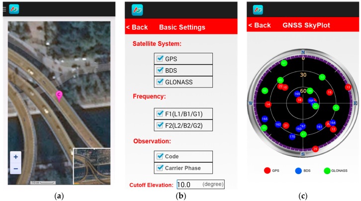
Based on the aforementioned approaches, a set of software for realizing BDS/GNSS real-time RTK services was developed from scratch, including the data processing software for DPC based on the Windows platform and the RTK positioning software running on smart devices based on the Android platform. Currently, this system can support real-time BDS, GPS, and GLONASS data processing and RTK positioning. Figure 3 shows some operation interfaces of the application software on the user side.
Figure 3.
Operation interfaces of user-side positioning software: (a) the interface for displaying the user’s position on a map; (b) the interface for setting the positioning parameters; and (c) the interface for the current sky plot of visible satellites.
3. Experiments and Results
3.1. Outline of the Experiments
In order to validate the performance of smart device–supported RTK positioning, both the static and kinematic tests were carried out in a real urban environment in Beijing, and each test included three cases. The reference station (named AOE) was installed on the roof of the building of the Academy of Opto-Electronics in Beijing with good observation conditions. The GNSS receiver used on the user-side was an OEM615 navigation module manufactured by the NovAtel Company, Canada. Figure 4 shows the experimental setup, including the appearance of the GNSS module (wallet-size). A Samsung Galaxy A7 smartphone was used in the tests for the data collection of the raw observations, ephemeris and corrections and the calculation of RTK positioning. The communication network accessed was the 3G/4G cellular communication network operated by the China Mobile Communications Corporation. The RS232-BT module was connected with the GNSS module for sending the raw GNSS data to the smartphone through the Bluetooth protocol. The devices used in the tests cost less than $1000 USD in total.
Figure 4.
The experimental setup.
In addition, in order to validate the positioning accuracy of the user’s real-time positioning results, the “true” position (with an accuracy of better than 5 cm) of the user for comparison was obtained by a high-performance GPS/INS (inertial navigation system) integrated receiver (installed in the experimental vehicle shown in Figure 4) which shared a common antenna with the user receiver via a power divider. The GNSS antenna was installed on the experimental vehicle, as shown in Figure 4. The positioning mode in all experiments was BDS/GPS combined single-epoch RTK positioning and the sampling rate of observation was 1 Hz. The cutoff elevation angle was set to 15 degrees and the constant error factors (a, b) for the stochastic model in Equation (7) were set as Equation (9), and the acceptable failure rate was set to Pf = 0.01 for FF-RT validation.
| (9) |
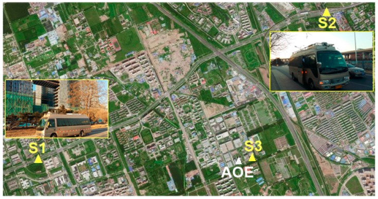
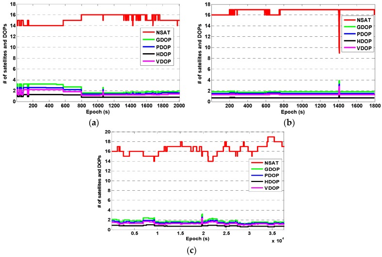
In the static test, experiments S1 and S2 were carried out on an urban road on 31 January 2016 and experiment S3 was carried out at the Academy of Opto-Electronics on 2 November 2016. The testing periods were about 35 min for S1, 30 min for S2, and 10.5 h for S3, respectively. The approximate locations of the user in each experiment are marked on the map shown in Figure 5. The number of visible BDS + GPS satellites (referred to as NSAT) and the corresponding dilution of precision (DOP), i.e., geometric DOP (GDOP), position DOP (PDOP), horizontal DOP (HDOP), and vertical DOP (VDOP), for experiments S1, S2, and S3 are shown in Figure 6, respectively. It can be seen that the number of visible BDS + GPS satellites in each experiment was about 16, and for most of the epochs the PDOP was smaller than 2.0 and the HDOP was about 1.0. It is worth noting that the dramatic drop of about seven satellites for three seconds in experiment S2 (Figure 6b) was due to the blockage of GNSS signals at one side which was caused by a very large vehicle passing by our experimental car.
Figure 5.
User sites in the static tests.
Figure 6.
The number of visible satellites and the corresponding DOPs in the static test: (a) experiment S1; (b) experiment S2; and (c) experiment S3.
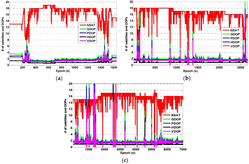
In the kinematic test, experiments K1 and K2 were carried out on 1 February 2016, and experiment K3 was carried out on 3 November 2016. The testing periods were about 25 min for K1, 45 min for K2, and 2 h for K3, respectively. The vehicle speed was about 50–80 km/h and the trajectories of each experiment are shown in Figure 7. The experimental routes covered the urban road and the highway. The longest distance (baseline) between the rover and the reference station was about 16 km (in K3). The number of visible BDS + GPS satellites and the corresponding DOPs for each experiment are shown in Figure 8. It can be seen that when the experimental vehicle drove on the road, the number of visible satellites and the corresponding DOPs varied significantly due to the obstructions caused by high-rise buildings, street canyons, and overhead viaducts, etc. When under good observation conditions, the number of visible satellites can reach 14–18. However, it declined to less than 10 (even less than four for a few epochs) visible satellites when the occlusions occurred and the DOPs of many epochs became dramatically larger due to the poor geometric distribution of the visible satellites.
Figure 7.
The vehicle trajectories of kinematic experiments K1, K2, and K3.
Figure 8.
The number of visible satellites and the corresponding DOPs in the kinematic test: (a) experiment K1; (b) experiment K2; and (c) experiment K3.
For all of the experiments, (1) the ambiguity fixed-rate was defined as the percentage of the ambiguity-fixed epochs to the whole testing period; (2) the fixed solutions mean that those positioning results were obtained with ambiguity parameters being fixed into integers; and (3) when the communication to the DPC failed for receiving the differential corrections, the solutions were derived from single-point positioning.
3.2. Results
3.2.1. Static Test
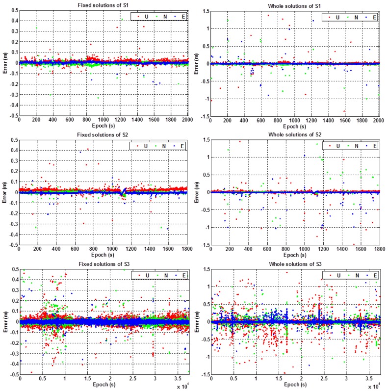
Figure 9 shows the positioning errors of the fixed solutions and the whole solutions in the east (E), north (N), and up (U) components for the three static experiments S1, S2, and S3, respectively. Table 2 illustrates the performances of ambiguity resolution and also the results of RMS value of the positioning errors in the horizontal (H) and vertical (V) components. In addition, Table 3 gives the percentages of the positioning errors at different levels, i.e., within 0.1 m, 0.2 m, 0.5 m, 1.0 m and larger than 1.0 m, for the static experiments S1, S2, and S3, respectively.
Figure 9.
Positioning errors of experiment S1 (top), S2 (middle), and S3 (bottom) in the static test.
Table 2.
The performances of RTK positioning in the static test.
| Experiments | Ambiguity Fixed-Rate (%) | RMS (m) | |||||
|---|---|---|---|---|---|---|---|
| Fixed Solutions | Unfixed Solutions | Whole Solutions | |||||
| H | V | H | V | H | V | ||
| S1 | 97.8 | 0.03 | 0.04 | 0.45 | 1.24 | 0.14 | 0.25 |
| S2 | 98.1 | 0.02 | 0.04 | 0.67 | 0.84 | 0.15 | 0.21 |
| S3 | 95.7 | 0.02 | 0.03 | 0.25 | 0.43 | 0.07 | 0.09 |
Table 3.
Percentages of positioning errors at different levels for the static test.
| Experiments | Error ≤ 0.1 m (%) | Error ≤ 0.2 m (%) | Error ≤ 0.5 m (%) | Error ≤ 1.0 m (%) | Error > 1.0 m (%) | |||||
|---|---|---|---|---|---|---|---|---|---|---|
| H | V | H | V | H | V | H | V | H | V | |
| S1 | 98.26 | 98.10 | 98.57 | 98.46 | 99.13 | 98.72 | 99.54 | 99.03 | 0.46 | 0.97 |
| S2 | 97.59 | 97.30 | 98.05 | 97.70 | 98.39 | 98.45 | 99.14 | 99.02 | 0.86 | 0.98 |
| S3 | 97.69 | 97.61 | 98.56 | 98.11 | 99.22 | 98.97 | 99.51 | 99.40 | 0.49 | 0.61 |
From Figure 9 and Table 2 and Table 3, we can see that: (1) the ambiguity fixed-rate of RTK positioning was about 97% on average for the static test; (2) the positioning errors of the fixed solutions were within 10 cm for most of the experimental periods, and the positioning errors of the unfixed solutions were within 1.5 m for most of the testing periods; (3) the positioning accuracy (RMS) of the RTK fixed solutions can achieve better than 3 cm in the horizontal component and 4 cm in the vertical component; (4) the percentages of the positioning errors that were within 0.5 m can reach up to more than 98% (both for the horizontal and vertical components) for the three static experiments; and (5) the positioning accuracy (RMS) of the whole solutions were better than 0.15 m and 0.25 m in the horizontal and the vertical components, respectively.
3.2.2. Kinematic Test
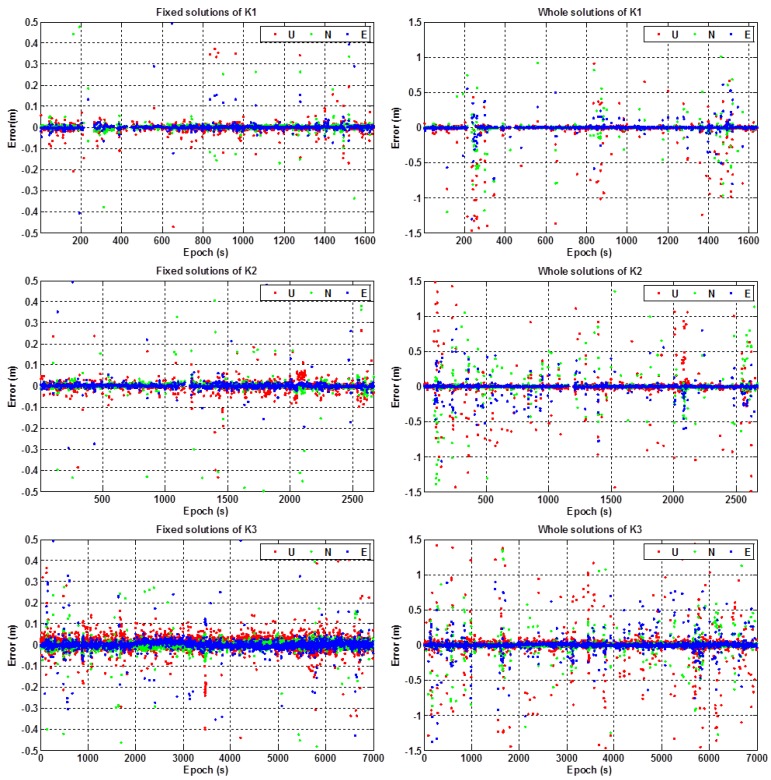
Figure 10 shows the positioning errors of the fixed solutions and the whole solutions in the east, north, and up components for the three kinematic experiments of K1, K2, and K3, respectively. Table 4 shows the performances of ambiguity resolution and the results of the RMS values of positioning errors in the horizontal and vertical components. In addition, Table 5 gives the percentages of the positioning errors at different levels, i.e., within 0.1 m, 0.2 m, 0.5 m, 1.0 m and larger than 1.0 m, for the kinematic experiments K1, K2, and K3, respectively.
Figure 10.
Positioning errors of experiment K1 (top), K2 (middle), and K3 (bottom) in the kinematic test.
Table 4.
The performances of RTK positioning in the kinematic test.
| Experiments | Ambiguity Fixed-Rate (%) | RMS (m) | |||||
|---|---|---|---|---|---|---|---|
| Fixed Solutions | Unfixed Solutions | Whole Solutions | |||||
| H | V | H | V | H | V | ||
| K1 | 92.4 | 0.08 | 0.12 | 1.07 | 1.25 | 0.24 | 0.40 |
| K2 | 90.6 | 0.09 | 0.13 | 1.15 | 1.78 | 0.28 | 0.47 |
| K3 | 93.5 | 0.11 | 0.14 | 1.23 | 1.42 | 0.32 | 0.45 |
Table 5.
Percentages of positioning errors at different levels for the kinematic test.
| Experiments | Error ≤ 0.1 m (%) | Error ≤ 0.2 m (%) | Error ≤ 0.5 m (%) | Error ≤ 1.0 m (%) | Error > 1.0 m (%) | |||||
|---|---|---|---|---|---|---|---|---|---|---|
| H | V | H | V | H | V | H | V | H | V | |
| K1 | 80.30 | 80.75 | 85.51 | 84.61 | 93.50 | 90.41 | 97.30 | 94.53 | 2.70 | 5.47 |
| K2 | 85.42 | 85.66 | 86.98 | 87.46 | 92.53 | 90.80 | 96.67 | 94.09 | 3.33 | 5.91 |
| K3 | 93.35 | 92.54 | 94.51 | 94.01 | 96.92 | 95.84 | 98.19 | 97.47 | 1.81 | 2.53 |
It can be seen from Figure 10 and Table 4 and Table 5 that: (1) the ambiguity fixed-rate of RTK positioning was better than 90% for the three kinematic experiments, which was a little lower than that of the static test; (2) as with the static test, the positioning errors of the fixed solutions were within 10 cm for most of the testing periods, and the positioning errors of the unfixed solutions were within 1.5 m for most of the testing periods; (3) the positioning accuracy (RMS) of the RTK fixed solutions on average can achieve about 10 cm in the horizontal component and 13 cm in the vertical component; (4) the percentages of the positioning errors that were within 0.5 m can reach up to more than 90% (both for the horizontal and vertical components) for the three kinematic experiments; and (5) the positioning accuracy (RMS) of the whole solutions during the testing periods was better than 0.30 m in the horizontal component and 0.45 m in the vertical component on average, respectively.
4. Conclusions
In this work, a feasible solution for achieving RTK positioning with sub-meter-level accuracy with a smart device and a low-cost GNSS terminal was proposed and a set of user-side application software for BDS/GNSS RTK positioning based on the Android platform was developed from scratch. The performance of the proposed solution was validated by static and kinematic BDS/GPS combined single-epoch RTK positioning in a real urban environment.
The experimental results show that: (1) for the static test, the ambiguity fixed-rate of RTK positioning was about 97%, and the positioning RMSs were better than 0.15 m in the horizontal component and 0.25 m in the vertical component, respectively; (2) for the kinematic test, whose performance was slightly worse than that of the static test, the ambiguity fixed-rate was better than 90%, and the positioning RMSs were better than 0.30 m in the horizontal component and 0.45 m in the vertical component, respectively; (3) the percentages of the positioning errors that were within 0.5 m (for the horizontal and vertical components) can reach up to more than 98% for the static test and 90% for the kinematic test. Therefore, the performance of the smart device–supported BDS/GNSS RTK positioning proposed and developed in this work has the potential to meet the demands of urban LBS with sub-meter precision.
In addition, future works will be mainly focused on: (1) the integration of the external low-cost GNSS module and the smart device for a complete positioning and navigation terminal and its real application in urban high-precision LBS; (2) the realization of network RTK (NRTK) positioning using a network of reference stations for larger coverage and higher accuracy; and (3) the possibility and potential for supporting real-time PPP and PPP-RTK positioning.
Acknowledgments
This work was partially supported by the National Key Research Program of China “Collaborative Precision Positioning Project” (No. 2016YFB0501900), the Key Laboratory for Urban Geomatics of the National Administration of Surveying, Mapping and Geoinformation, the China Natural Science Funds (No. 41304034, 41674043, 41574033, 41504035 and 41621063), the National High-Tech R&D Program of China (863 Program 2014AA123503). The first author also acknowledges the financial support of the China Scholarship Council. In addition, the authors would like to thank Yanqing Hou at the National University of Defense Technology and Renli Zhang at the University of the Chinese Academy of Sciences for their kindly help on improving the manuscript.
Author Contributions
Zishen Li conceived the initial idea for this work; Liang Wang, Zishen Li, Jiaojiao Zhao, Kai Zhou and Zhiyu Wang developed the software together; Liang Wang performed the experiments, analyzed the data and wrote the paper; Zishen Li, Hong Yuan, Jiaojiao Zhao and Kai Zhou helped to improve the manuscript. All components of this work were carried out under the supervision of Hong Yuan and Zishen Li.
Conflicts of Interest
The authors declare no conflict of interest.
References
- 1.Fu Y. The opportunities and challenges of applications in LBS for BeiDou navigation satellite system. Satell. Netw. 2014;6:28–32. (In Chinese) [Google Scholar]
- 2.Yang Y., Li J., Xu J., Tang J., Guo H., He H. Contribution of the compass satellite navigation system to global PNT users. Chin. Sci. Bull. 2011;56:2813–2819. doi: 10.1007/s11434-011-4627-4. [DOI] [Google Scholar]
- 3.Odolinski R., Teunissen P., Odijk D. Combined BDS, Galileo, QZSS and GPS single-frequency RTK. GPS Solut. 2015;19:151–163. doi: 10.1007/s10291-014-0376-6. [DOI] [Google Scholar]
- 4.China Satellite Navigation Office (CSNO) BeiDou Navigation Satellite System Signal in Space Interface Control Document Open Service Signal (version 2.0) CSNO; Beijing, China: 2013. [Google Scholar]
- 5.Yang Y., Li J., Wang A., Xu J., He H., Guo H., Shen J., Dai X. Preliminary assessment of the navigation and positioning performance of BeiDou regional navigation satellite system. Sci. China Earth Sci. 2014;57:144–152. doi: 10.1007/s11430-013-4769-0. [DOI] [Google Scholar]
- 6.Teunissen P., Odolinski R., Odijk D. Instantaneous BeiDou + GPS RTK positioning with high cut-off elevation angles. J. Geod. 2014;88:335–350. doi: 10.1007/s00190-013-0686-4. [DOI] [Google Scholar]
- 7.Odolinski R., Teunissen P. Single-frequency, dual-GNSS versus dual-frequency, single-GNSS: A low-cost and high-grade receivers GPS-BDS RTK analysis. J. Geod. 2016;90:1255–1278. doi: 10.1007/s00190-016-0921-x. [DOI] [Google Scholar]
- 8.Wang L., Wen X., Huang C. China Satellite Navigation Conference (CSNC) 2016 Proceedings: Volume I. Springer; Singapore: 2016. Application of low cost GPS/BDS receiver in UAV precise navigation and positioning; pp. 165–174. [Google Scholar]
- 9.Mongrédien C., Doyen J., Ström M., Ammann D. Centimeter-level positioning for UAVs and other mass-market applications; Proceedings of the ION GNSS; Portland, OR, USA. 12–16 September 2016. [Google Scholar]
- 10.Stempfhuber W., Buchholz M. A precise, low-cost RTK GNSS system for UAV applications; Proceedings of the International Conference on Unmanned Aerial Vehicle in Geomatics; Zurich, Switzerland. 14–16 September 2012. [Google Scholar]
- 11.Ji S., Gao Z., Wang W. M-DGPS: Mobile devices supported differential global positioning system algorithm. Arab. J. Geosci. 2015;8:6667–6675. doi: 10.1007/s12517-014-1699-x. [DOI] [Google Scholar]
- 12.Guo C., Guo W., Cao G., Dong H. A lane-level LBS system for vehicle network with high-precision BDS/GPS positioning. Comput. Intell. Neurosci. 2015;2015:531321. doi: 10.1155/2015/531321. [DOI] [PMC free article] [PubMed] [Google Scholar]
- 13.BeiDou’s Ground-Based Augmentation System Started Its Operation. [(accessed on 6 December 2016)]; Available online: http://www.beidou.gov.cn/2016/05/19/20160519a0a2567105fb4614baa1b3747848d743.html. (In Chinese)
- 14.Wang L., Li Z., Yuan H., Zhou K. Validation and analysis of the performance of dual-frequency single-epoch BDS/GPS/GLONASS relative positioning. Chin. Sci. Bull. 2015;60:857–868. doi: 10.1360/N972014-00789. (In Chinese) [DOI] [Google Scholar]
- 15.He H., Li J., Yang Y., Xu J., Guo H., Wang A. Performance assessment of single- and dual-frequency BeiDou/GPS single-epoch kinematic positioning. GPS Solut. 2014;18:393–403. doi: 10.1007/s10291-013-0339-3. [DOI] [Google Scholar]
- 16.Carcanague S. Low-Cost GPS/GLONASS Precise Positioning Algorithm in Constrained Environment. Institut National Polytechnique de Toulouse; Toulouse, France: 2013. [Google Scholar]
- 17.Wang L., Li Z., Yuan H., Zhou K. Assessment and comparison of typical BeiDou navigation- and surveying-type terminals on single-epoch positioning performance. Satell. Navig. 2015;3:34–40. (In Chinese) [Google Scholar]
- 18.Wübbena G., Schmitz M., Bagge A. PPP-RTK: Precise point positioning using state-space representation in RTK networks; Proceedings of the 18th International Technical Meeting of the Satellite Division of the Institute of Navigation; Long Beach, CA, USA. 13–16 September 2005; pp. 2584–2594. [Google Scholar]
- 19.Collins P. Isolating and estimating undifferenced GPS integer ambiguities; Proceedings of the 2008 National Technical Meeting of the Institute of Navigation; San Diego, CA, USA. 28–30 January 2008; pp. 720–732. [Google Scholar]
- 20.Ge M., Gendt G., Rothacher M., Shi C., Liu J. Resolution of GPS carrier-phase ambiguities in precise point positioning (PPP) with daily observations. J. Geod. 2008;82:389–399. doi: 10.1007/s00190-007-0187-4. [DOI] [Google Scholar]
- 21.Laurichesse D., Mercier F., Berthias J., Broca P., Cerri L. Integer ambiguity resolution on undifferenced GPS phase measurements and its application to PPP and satellite precise orbit determination. Navigation. 2009;56:135–149. doi: 10.1002/j.2161-4296.2009.tb01750.x. [DOI] [Google Scholar]
- 22.Geng J., Meng X., Dodson A., Teferle F. Integer ambiguity resolution in precise point positioning: Method comparison. J. Geod. 2010;84:569–581. doi: 10.1007/s00190-010-0399-x. [DOI] [Google Scholar]
- 23.Teunissen P., Khodabandeh A. Review and principles of PPP-RTK methods. J. Geod. 2015;89:217–240. doi: 10.1007/s00190-014-0771-3. [DOI] [Google Scholar]
- 24.Odijk D., Zhang B., Khodabandeh A., Odolinski R., Teunissen P. On the estimability of parameters in undifferenced, uncombined GNSS network and PPP-RTK user models by means of S-system theory. J. Geod. 2015;90:15–44. doi: 10.1007/s00190-015-0854-9. [DOI] [Google Scholar]
- 25.Wang L., Li Z., Yuan H., Zhao J., Zhou K. China Satellite Navigation Conference (CSNC) 2016 Proceedings: Volume I. Springer; Singapore: 2016. Research and implementation on BDS/GNSS real-time positioning for urban high-precision location-based services; pp. 277–286. [Google Scholar]
- 26.Deng C., Tang W., Liu J., Shi C. Reliable single-epoch ambiguity resolution for short baselines using combined GPS/BeiDou system. GPS Solut. 2014;18:375–386. doi: 10.1007/s10291-013-0337-5. [DOI] [Google Scholar]
- 27.Teunissen P., Kleusberg A. GPS for Geodesy. 2nd ed. Springer; Berlin/Heidelberg, Germany: 1998. [Google Scholar]
- 28.King R., Bock Y. Documentation for the GAMIT GPS Analysis Software. Massachusetts Institute of Technology; Cambridge, MA, USA: 1999. [Google Scholar]
- 29.Teunissen P. The least-squares ambiguity decorrelation adjustment: A method for fast GPS integer ambiguity estimation. J. Geod. 1995;70:65–82. doi: 10.1007/BF00863419. [DOI] [Google Scholar]
- 30.Chang X., Yang X., Zhou T. MLAMBDA: A modified LAMBDA method for integer least-squares estimation. J. Geod. 2005;79:552–565. doi: 10.1007/s00190-005-0004-x. [DOI] [Google Scholar]
- 31.Teunissen P. GNSS integer ambiguity validation: Overview of theory and methods; Proceedings of the Institute of Navigation Pacific PNT; Honolulu, HI, USA. 23–25 April 2013; pp. 673–684. [Google Scholar]
- 32.Teunissen P., Verhagen S. The GNSS ambiguity ratio-test revisited: A better way of using it. Surv. Rev. 2009;41:138–151. [Google Scholar]
- 33.Verhagen S., Teunissen P. The ratio test for future GNSS ambiguity resolution. GPS Solut. 2012;17:535–548. doi: 10.1007/s10291-012-0299-z. [DOI] [Google Scholar]
- 34.Li L., Li Z., Yuan H., Wang L., Hou Y. Integrity monitoring-based ratio test for GNSS integer ambiguity validation. GPS Solut. 2016;20:573–585. doi: 10.1007/s10291-015-0468-y. [DOI] [Google Scholar]
- 35.Wang L., Verhagen S. A new ambiguity acceptance test threshold determination method with controllable failure rate. J. Geod. 2014;89:361–375. doi: 10.1007/s00190-014-0780-2. [DOI] [Google Scholar]
- 36.Hou Y., Verhagen S., Wu J. An efficient implementation of fixed failure-rate ratio test for GNSS ambiguity resolution. Sensors. 2016;16:945. doi: 10.3390/s16070945. [DOI] [PMC free article] [PubMed] [Google Scholar]
- 37.Li J., Yang Y., Xu J., He H., Guo H., Wang A. China Satellite Navigation Conference (CSNC) 2013 Proceedings. Springer; Berlin/Heidelberg, Germany: 2013. Performance analysis of single-epoch dual-frequency RTK by BeiDou navigation satellite system; pp. 133–143. [Google Scholar]
- 38.Wang L., Li Z., Yuan H., Zhao J., Zhou K., Yuan C. Influence of the time-delay of correction for BDS and GPS combined real-time differential positioning. Electron. Lett. 2016;52:1063–1065. doi: 10.1049/el.2015.4032. [DOI] [Google Scholar]
- 39.Xu Y., Li Q., Xie S., Zhang L. Study on algorithm and communication protocol of differential GPS positioning based on pseudorange; Proceedings of the International Forum on Information Technology and Applications; Chengdu, China. 15–17 May 2009; pp. 606–609. [Google Scholar]


