Abstract
The explicit and semi-implicit schemes in flow simulations involving complex geometries and moving boundaries suffer from time-step size restriction and low convergence rates. Implicit schemes can be used to overcome these restrictions, but implementing them to solve the Navier-Stokes equations is not straightforward due to their non-linearity. Among the implicit schemes for nonlinear equations, Newton-based techniques are preferred over fixed-point techniques because of their high convergence rate but each Newton iteration is more expensive than a fixed-point iteration. Krylov subspace methods are one of the most advanced iterative methods that can be combined with Newton methods, i.e., Newton-Krylov Methods (NKMs) to solve non-linear systems of equations. The success of NKMs vastly depends on the scheme for forming the Jacobian, e.g., automatic differentiation is very expensive, and matrix-free methods without a preconditioner slow down as the mesh is refined. A novel, computationally inexpensive analytical Jacobian for NKM is developed to solve unsteady incompressible Navier-Stokes momentum equations on staggered overset-curvilinear grids with immersed boundaries. Moreover, the analytical Jacobian is used to form preconditioner for matrix-free method in order to improve its performance. The NKM with the analytical Jacobian was validated and verified against Taylor-Green vortex, inline oscillations of a cylinder in a fluid initially at rest, and pulsatile flow in a 90 degree bend. The capability of the method in handling complex geometries with multiple overset grids and immersed boundaries is shown by simulating an intracranial aneurysm. It was shown that the NKM with an analytical Jacobian is 1.17 to 14.77 times faster than the fixed-point Runge-Kutta method, and 1.74 to 152.3 times (excluding an intensively stretched grid) faster than automatic differentiation depending on the grid (size) and the flow problem. In addition, it was shown that using only the diagonal of the Jacobian further improves the performance by 42 – 74% compared to the full Jacobian. The NKM with an analytical Jacobian showed better performance than the fixed point Runge-Kutta because it converged with higher time steps and in approximately 30% less iterations even when the grid was stretched and the Reynold number was increased. In fact, stretching the grid decreased the performance of all methods, but the fixed-point Runge-Kutta performance decreased 4.57 and 2.26 times more than NKM with a diagonal Jacobian when the stretching factor was increased, respectively. The NKM with a diagonal analytical Jacobian and matrix-free method with an analytical preconditioner are the fastest methods and the superiority of one to another depends on the flow problem. Furthermore, the implemented methods are fully parallelized with parallel efficiency of 80–90% on the problems tested. The NKM with the analytical Jacobian can guide building preconditioners for other techniques to improve their performance in the future.
Keywords: Implicit method, Complex geometry, Newton-Krylov method, Overset, Curvilinear
1. Introduction
Simulating flows involving arbitrarily moving complex geometries are of interest in many areas, such as flow inside the vascular systems [1, 2, 3, 4, 5, 6, 7], swimming/flying in nature [8, 9, 10, 11, 12, 13], flows with suspended particles [14, 15, 16], etc. Currently, one of the main challenges in simulating such flows is the small time-step size restriction, e.g., Griffith [17] discussed the severe restriction on the time-step size imposed by his explicit scheme in simulations of an aortic heart valve using the immersed boundary method. Mittal et al. [18] used an implicit Crank-Nicolson scheme for the diffusion terms to eliminate the numerical instabilities, while the non-linear convective terms were treated explicitly in their immersed boundary method. The simulations of Mangual et al. [19], Domenichini and Pedrizzetti [20], de Tullio et al. [21], and Tytell et al. [22] all used the immersed boundary method, which sets small time-step restrictions due to their explicit nature. Robust implicit time integrations are needed to reduce the time-step limitations of such simulations, which will lower the computational cost and allow for higher spatial resolution. However, developing fully implicit methods for Navier-Stokes equations is not straightforward due to their non-linearity. In these cases, the methods for solving non-linear systems of equations need to be employed. There are two main categories of implicit solvers for non-linear systems of equations: 1) fixed-point methods; and 2) Newton-based methods. The applied mathematics community has emphasized on Newton-based methods for boundary value problems in which the steady-state solution of non-linear equations is desired [23]. However, the computational physics community has focused on fixed-point type methods for initial value problems, where dynamic evolution of the equations is required [23].
The first category is interchangeably named as fixed-point, Picard linearization, and successive substitution method [24]. The fixed-point method for solving the system of non-linear algebraic equations F(U⃗) = 0 can be written as:
| (1) |
where k is the fixed-point iteration index. Dual time-stepping methods can be viewed as a fixed-point iteration as well [25, 26]. Fixed-point methods are implemented in conjunction with the pressure-velocity coupling algorithms such as artificial compressibility [26], SIMPLE family [27], PISO [28], and fractional-step [29] for solving incompressible Navier-Stokes equation. Fractional-step requires smaller time-step size in comparison to SIMPLE and PISO, while it requires less correction iterations than SIMPLE and PISO [30].
The second category is the Newton method, which is a classical algorithm for finding a solution to the system of non-linear algebraic equations F(U⃗) = 0 [31, 32]. Given an initial guess U⃗(0), a sequence of steps ΔU⃗(k) is computed as follows:
| (2) |
where k is Newton iteration index and is the associated Jacobian matrix [31, 33]. The Newton Eq. (2) is a system of linear algebraic equations which must be solved at each Newton iteration (k). Newton-based methods have been previously implemented in conjunction with the pressure-velocity coupling algorithms such as velocity-vorticity method [34, 35], as a multigrid smoother in a SIMPLE method [36], and fractional-step [37] for solving incompressible Navier-Stokes equation. The main advantage of Newton methods over fixed-point type methods is the ability to take large time-steps and super-linear convergence rates [38]. On the other hand, requiring a sufficiently good initial condition is the Newton methods’ drawback [39, 38]. Considering the advantages of Newton methods, they are implemented in this framework and are systematically compared against a fixed-point method.
The Newton equation at each k can be solved by either direct or iterative methods. Because A is typically approximated (the approximation of A does not affect the solution as long as the Newton iterations converge) and the initial condition is typically far from the solution, the exact solution at each iteration (k) may not be justified. Therefore, an iterative method is typically used for solving Newton equations at each iteration. In this case, the exact solution of Eq. (2) is not obtained at each iteration k, which is referred to as the inexact Newton method [40]. Therefore, a strict quadratic convergence is typically not achieved [23]. Some of the most advanced iterative methods are the Krylov subspace methods [41, 42, 43, 44] including the generalized minimal residual method (GMRES) [45] and preconditioned GMRES [46]. Krylov subspace methods were introduced by Hestenes et al. [47] and Reid [48] as iterative methods to solve large linear systems of equations.
For solving Newton equations using a Krylov subspace method either the Jacobian (A) or the Jacobian-vector product (AΔU⃗) should be formed by: (a) a matrix-free (MF); (b) an automatic differentiation (AD); or (c) an analytical Jacobian method. In MF, the Jacobian matrix is not explicitly formed because Krylov subspace methods only require the Jacobian-vector product to carry out the iterations (not the individual elements of the Jacobian) [23]. However, successful application of MF to any given problem depends on the appropriate preconditioner, which might be challenging to obtain [23]. In AD, the Jacobian (not the Jacobian-vector product) is approximated using automatic differentiation [49]. This method can accelerate convergence by more than an order of magnitude relative to an explicit solver [50]. AD was reported to improve the performance and robustness of a finite volume scheme by using a set of techniques for computing accurate derivatives of non-linear functions compared to an approximate one [51]. Also, the vertex-elimination, automatic differentiation approach was used to calculate the Jacobians of functions as efficient as hand-coded Jacobian [52]. However, forming the complete Jacobian for a large system of equations is extremely expensive because it requires many evaluations of the discretized equations to approximate the Jacobian’s derivatives [23]. Finally, the Jacobian is formed analytically in analytical Jacobian. Briley-McDonald [53] and Beam-Warming [54, 55] pioneered applying analytical Jacobian to solve the compressible Navier-Stokes equations in curvilinear coordinates (partial transformation, i.e., the dependent variables such as velocities are in Cartesian coordinates but the derivatives are in curvilinear coordinates) on non-staggered grids. An application of Beam-Warming method in two-dimensions (2D) was first presented by Steger [56] and in 3D by Pulliam and Steger [57]. Pulliam et al. introduced a diagonalization of the Jacobian blocks for decreasing the computational cost [58]. In fact, the Jacobian of the Navier-Stokes in Cartesian or partial transformation into curvilinear coordinates on non-staggered grids is known [59, 30], which has applied to implicitly solve compressible and incompressible flows. However, there is no analytical Jacobian, to the best of the authors’ knowledge, derived or used for fully transformed Navier-Stokes equations on staggered grids. In fact, the derivation of an analytical Jacobian for advanced schemes, such as upwind methods, can become very complex as recognized by several researchers [60, 51, 61].
We are interested in discretizing the Navier-Stokes equations on staggered grids because using non-staggered grids requires adding a fourth-order dissipation to the pressure-Poisson equation to avoid odd-even decoupling and obtain a smooth pressure field, which can produce large errors near moving boundaries that typically create large pressure gradients [62]. The fourth-order dissipation does not allow the discrete continuity equation to be satisfied to machine zero. However, the discretization on staggered grids does not require adding the dissipation term. Therefore, if staggered grids are used, the discrete continuity equation on the control volume can be satisfied to machine zero given that the pressure-Poisson equation converges to machine zero. To clarify the difficulties in the derivation of an analytical Jacobian on a staggered grid, for example, Fig. 1 presents the stored location of variables U1 and U2 and non-linear functions F1 and F2 on a 2D staggered grid. Statement (3) is the part of the Jacobian for the cell plotted in Fig. 1, which is multiplied by the corresponding
Figure 1.
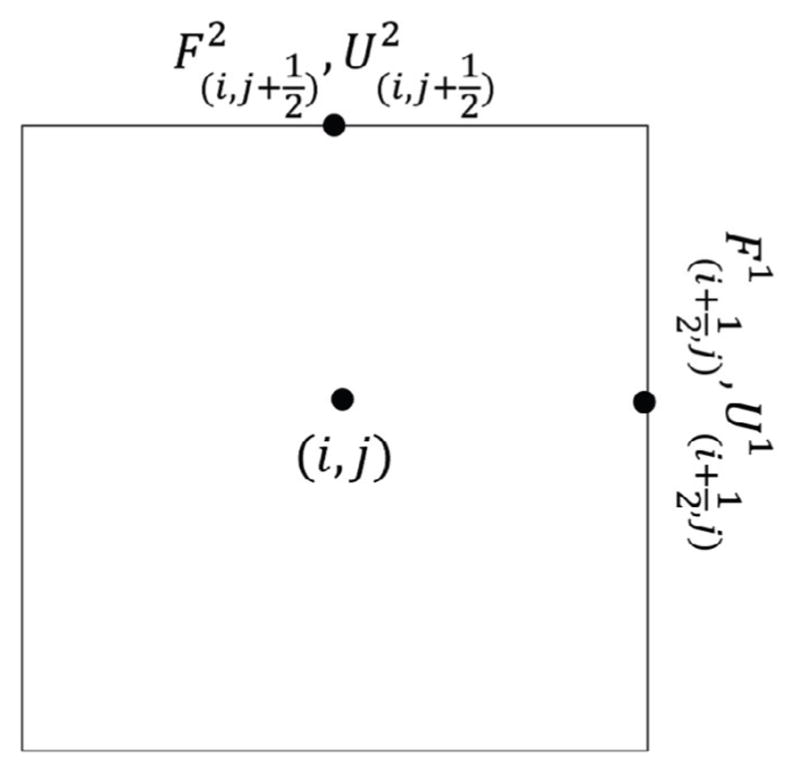
The stored location of variables U1 and U2 and non-linear functions F1 and F2 on a 2D staggered grid. The (i, j) is at the center of the control volume and the variables are stored on the faces of the control volume.
| (3) |
The major difficulty here is to compute and terms, in which the numerator and denominator of the derivatives are not stored at the same location (Fig. 1). This adds to the difficulties in obtaining the Jacobian for full transformation of Navier-Stokes in curvilinear coordinates, which would involve Christoffel symbols. We overcome these difficulties through the hybrid staggered/non-staggered approach [63] and taking a set of appropriate discretizations and interpolations, explained thoroughly in Section 2.3.1. Note that we do not form the Jacobian by taking average of the variables from the staggered locations and compute them at the center point using the non-staggered formulation for the Jacobian. This will not solve the problem for these derivatives because, for example, is not equal to . Furthermore, there are several choices for the discretizations and interpolations. We have tested different discretizations and interpolations for forming the analytical Jacobian to reach to the one that is closest to the numerical Jacobian obtained by the automatic differentiation scheme.
The goal here is to improve upon the current implicit MF and the semi-implicit, fixed-point Runge-Kutta scheme (FPRK) [63, 37], and achieve a faster method for solving flows involving complex geometries. Therefore, the developed methods must work with our immersed boundary and also overset grid techniques [64]. Combination of immersed boundary and overset grid techniques enable us to efficiently study flows in highly complicated geometries without wasted computational nodes located outside of the region of interest [64]. We have derived an analytical Jacobian, to implicitly solve Navier-Stokes equation on staggered grids using Newton-Krylov method, which also works with our immersed boundary and overset grid techniques. We have used the derived analytical Jacobian as a preconditioner to improve the convergence rate of MF. Furthermore, AD is added to the developed methods to guide the development of the analytical Jacobian and to systematically compare all of the Jacobian formation schemes. There have been a few studies on numerical analysis of MF [65, 66, 67] and FPRK [68, 69], but studies that compare different methods on a realistic problems do not exist. This paper provides insights on different numerical aspects of widely used NKMs (MF, AD, and analytical Jacobian) and FPRK by comparing the results of convergence rate, optimum CFL, and the required iterations and also Grid size, topology, Re, and time-step effect on the computational time of aforementioned methods. Furthermore, we comprehensively compare the computational time of the NKM with a simplified analytical Jacobian (diagonal analytical Jacobian) and the full Jacobian. There is no agreement on the superiority of diagonal or full Jacobian over the other in terms of computational time, e.g., some state diagonal [70] whereas others state full Jacobian [71, 72] is faster. Our comparisons reveal the superior Jacobian for implicit solution of the incompressible Navier-Stokes equations.
This paper is organized as follows: In the numerical method Section 2, we present the governing equations in curvilinear coordinates. Then, we provide a brief overview of AD and MF, followed by a detailed explanation of the derivation of the analytical Jacobian. Finally, we describe the modifications required for this method to work with immersed boundaries and overset grids. In the validations and verifications Section 3, we present several cases to show the accuracy and capabilities of our developed methods. The Taylor-Green vortex problem verifies the 2nd order accuracy of the method on curvilinear grids. The comparison of numerical results from the steady and pulsatile flow through the 90° bend against experimental data further validates the method and its consistency on overset grids. In addition, the comparison of numerical results from the inline oscillation of a cylinder against experimental data validates the method for flows with moving immersed boundaries. The inline oscillation of a cylinder problem verifies the 2nd order accuracy of the method with moving immersed boundaries. In computational performance Section 4, these numerical examples are used to explore different aspects of the developed method such as parallel efficiency, effect of grid size, topology, Re, and time-step on the computational time and verify the improvements of computational time of analytical Jacobian against FPRK, MF, and AD. At the end of this section, the performance of the developed method for a realistic application is explored. At the end, the findings of this study and the future directions are summarized in Section 5.
2. Numerical method
We use the following notations throughout this paper: superscript with parenthesis (e.g., U(*)) for the time level, and subscript with parenthesis for location (e.g., ). Also, subscript without parenthesis indicates direction in Cartesian coordinates (e.g., uq, and xq) and, superscript without parenthesis indicates direction in curvilinear co-ordinates (e.g., Um, and ξm). Vectors and matrices are represented by → and bold symbols (e.g., A), respectively. Component of matrix at mth row and nth column is presented by Amn. Einstein’s tensor notation, where repeated indices imply summation, is used unless otherwise indicated (k, d, and q = 1,2,3).
2.1. The governing equations
The governing equations are the 3D, unsteady incompressible Navier-Stokes equations for a Newtonian fluid in curvilinear coordinates. A generalized curvilinear coordinate mapping is employed to transform equations from Cartesian (x1, x2, x3) to curvilinear (ξ1, ξ2, ξ3) coordinates, where ξm = ξm(x1, x2, x3). The curvilinear formulation is based on the hybrid staggered/non-staggered approach [37], which has all the advantages of a pure staggered grid formulation (i.e., satisfies the discrete continuity exactly) and eliminates the need for computing the Christoffel symbols. The governing equations read as follows [37]:
| (4) |
| (5) |
where uq, P, and t are the non-dimensional Cartesian velocity, pressure, and physical time, respectively, and Re is the Reynolds number of the flow based on characteristic length and velocity scales. In Eq. (4–5), J is the Jacobian of the geometric transformation, J = ∂( ξ1, ξ2, ξ3)/∂(x1, x2, x3), gkd is the contravariant metric tensor, , and Uq are the contravariant velocity components, which are correlated with the Cartesian velocity components as follows:
| (6) |
The Cartesian velocity is related with the contravariant velocity components as follows:
| (7) |
where and symbols indicate and , respectively. In our hybrid staggered/non-staggered approach, the pressure and the Cartesian velocities are stored at the center of the control volume (i, j,k), and the contravariant velocity components are stored at the center of the control volume’s surfaces ( , j, k), (i, , k), and (i, j, ) for U1, U2, and U3, respectively [37].
2.2. Overview of the overset-CURVIB
The curvilinear/immersed boundary (CURVIB) and overset grid methods are extensively described and validated previously [64, 37, 63], but we provide a brief overview of these methods in this section for completeness. The governing Eq. (4) and (5) are advanced in time using a fractional step method on a curvilinear grid [37]. The momentum Eqs. (5) are discretized in time in a fully implicit manner using a second-order backward difference:
| (8) |
where n denotes the physical time level and . The convection term and the viscous term in the RHS are discretized using QUICK and three-point central finite difference schemes, respectively. These terms are calculated on the center nodes of a cell similar to other non-staggered methods, then interpolated to cell faces to form the RHS for the contravariant velocities which are stored at the staggered locations [37]. Eq. (8) is solved implicitly using an NKM (discussed in Section 2.3 and 2.3.1) or FPRK to obtain intermediate fluxes U⃗(*). The intermediate fluxes are not divergence-free and need to be corrected to satisfy the continuity Eq. (4). This is accomplished by solving the following Poisson equation for the pressure correction ϕ = P(n+1) − P(n):
| (9) |
where is the gradient operator. The Poisson equation Eq. (9) is solved using GMRES with multigrid as a preconditioner [37]. Obtaining the solution of the Poisson equation, the pressure and contravariant velocities are updated as follows:
| (10) |
| (11) |
2.3. Solving the momentum equation
The system of non-linear algebraic equations that results from implicit discretization of the Navier-Stokes, i.e., Eq. (8) gives:
| (12) |
This equation can be solved by either a Newton method or a dual time-stepping method. In our framework, we have implemented both to compare and contrast them on realistic problems. The dual time-stepping method, which can be viewed as fixed-point iteration (Eq. 1), is formulated as follows:
| (13) |
where k is the dual time iteration index and Δτ is the dual time-step. A sequence of steps in the dual time-stepping method is computed by ΔU⃗(k) = U⃗(k+1) − U⃗(k). The Newton method can be written as:
| (14) |
where is the Jacobian matrix and ΔU⃗(k) = U⃗(k+1) − U⃗(k) is a sequence of steps in the Newton equations. Given U⃗(0) = U⃗(n), the Newton iteration continues until F⃗(U⃗(k)) → 0, at which U⃗(k+1) U⃗(*) (k = 0,1,2,…). A in the Newton Eq. (14) can be approximated because as long as , then , i.e, F⃗(U⃗(k)) → 0 converges to the desired accuracy. Therefore, an approximate Jacobian can be used instead of the exact Jacobian. Three most commonly used techniques to form the approximate Jacobian are: (1) the approximate analytical; (2) automatic differentiation; and (3) matrix-free method.
The Jacobian can be formed by taking the numerical derivative of F with respect to U⃗, which is recognized as the automatic differentiation (AD) technique [50] as follows:
| (15) |
Another approach is the matrix-free method, which does not require forming the Jacobian explicitly, if a Krylov subspace method is used for solving Eq. (14). Krylov methods only require the product of the Jacobian (A) and the vector (U⃗), which be approximated by [31]:
| (16) |
where U⃗ is the current approximation to the root of the system of equations, V⃗ is the orthonormal basis of Krylov subspace, and σ is a scalar [31].
Finally, A can be formed taking analytical derivatives of the system of equations with respect to U⃗. The analytical Jacobian has been previously derived and used on non-staggered grids [57, 54]. However, to the best of the authors’ knowledge, it has not been derived for staggered grids as discussed in the introduction (Fig. 1). We explain the formation of the analytical Jacobian in Section 2.3.1.
We have implemented all of the above technique in approximating the Jacobian, i.e., AD, MF, and analytical Jacobian in our CURVIB framework. After approximating the Jacobian, we need to solve Eq. (14). If the number of unknowns is large, computing the exact solution using a direct method for solving Eq. (14) at each Newton iteration (k) can be expensive and may not be justified when initial condition is far from the solution. Therefore, it is reasonable to use an iterative method to solve this equation within the required accuracy [40]. We use flexible GMRES (FGM-RES) [46] in AD, MF, analytical Jacobian for solving Eq. (14) at each k as the Krylov-subspace iterative method using PETSc libraries [73]. The restarting iteration number for FGMRES algorithm is 30, and the relative residual, which is defined as (|| ||2 indicates the 2 norm), is fixed to 10−3 (l = 0, 1, 2,…). Also, we use the Jacobi preconditioner [74] for the FGMRES in all Newton methods.
2.3.1. The approximate analytical Jacobian
The major difficulties of forming an analytical Jacobian for full transformation of Navier-Stokes in curvilinear coordinates on staggered grids are: (1) the numerator and denominator of the derivatives in Jacobian are not stored at the same location in staggered grids; and (2) obtaining the Jacobian for full transformation of Navier-Stokes in curvilinear coordinates involves Christoffel symbols. Christoffel symbols were avoided in the full transformation of RHS in Eq. 8 (not the Jacobian) by using indirect transformation in the hybrid staggered/non-staggered approach [37]. In this approach, first the partially transformed RHS is calculated based on the Cartesian variables stored at non-staggered locations, and then it is interpolated to the staggered locations and multiplied by the appropriate metrics of transformation to form the final RHS for the contravariant velocities on the staggered locations. Because in this indirect transformation the RHS is written in terms of the Cartesian velocities and not the contravariant ones and the RHS calculation involves interpolations, deriving the Jacobian by linearizing the discrete RHS is not the best choice. Instead, we start from the analytical RHS and apply appropriate discretizations, interpolations, and simplifications required to resolve theses difficulties, which are explained in this section.
We derive the Jacobian A on staggered grids from the momentum Eq. (5), which is written for the contravariant velocities at the staggered locations:
| (17) |
Applying a multivariate Taylor expansion about a U(n), and removing higher order terms, and Eq. (17) at current time-step n yields:
| (18) |
where δkp is the Kronecker delta. In order to derive the Jacobian, it is necessary to make some simplifications. These simplifications are acceptable as long as the Newton equations converge to the desired accuracy because the right-hand side of Eq. (14) is not affected by these simplifications. It is assumed that the metrics of transformation , gkd, and J are locally constant, e.g., , to avoid dealing with their derivative, i.e., the Christoffel symbols, which are expensive to calculate and put extra constraints on the smoothness of the curvilinear grid. Off-diagonal components of the contravariant metric tensor gkd are negligible relative to the diagonal components. Therefore, gkd is approximated by only the diagonal part. Applying these simplifications on Eq. (18) leads to:
| (19) |
Note that is obtained by discretizing the unsteady acceleration term with second-order backward difference with respect to time similar to Eq. (8). Furthermore, is used for obtaining Eq. (19).
The major challenge here is determining the terms in Eq. (19) such as or , in which k ≠ m. The reason is that Um for m = 1,2,3 are not computed and stored at all surfaces (see Fig. 1) and only stored on the corresponding staggered locations. Therefore, some interpolations are required to determine these terms. Our experience shows that the convergence rate of the Newton equations Eq. (14) directly depends on such interpolations. To illustrate how these interpolations are chosen, Eq. (19) is written in 2D, and m = 1 for clarity without the loss of generality (the implementation in 3D is provided in the Appendix A). When m = 1, all the terms at the right-hand side of Eq. (19) are stored at ( , j).
| (20) |
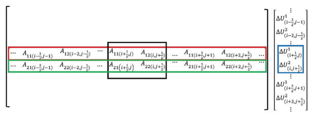
By discretizing the derivatives of the right-hand side of Eq. (20), all the resulting terms must be formed such that they contain ΔU1 and ΔU2 at the corresponding surface centers (i.e., ( , j + c) and (i + c, ), respectively). s and c are the integer numbers (s ≠ 0) that determine the location of the surfaces. Note that the limit of s and c are determined based on the discretization and interpolations of the right-hand side of Eq. (20). The Jacobian matrix components, A11 and A12, are found by deriving the coefficients of ΔUm in the right-hand side of Eq. (20), which must include U1,U2,g11, and g22 at the corresponding surface center. For clarification in Fig. 2, the assembled Jacobian matrix is plotted schematically for a 2D grid. Red and green rectangles correspond to coefficients for row 2 ×( j × I M + i) and 2 ×( j × I M + i) + 1 (I M and JM are the number of nodes in ξ1 and ξ2 direction, respectively) of the Jacobian, respectively, and the black rectangle shows the sub-Jacobian matrix, which is multiplied by the corresponding increment of contravariant velocities (blue rectangle). The Jacobian matrix contains I M × JM number of these sub-Jacobians.
Figure 2.
Schematic of assembled Jacobian matrix in two dimensional equations.
The terms of the right-hand side of Eq. (20) are labeled in order to expand and illustrate them in detail. The unsteady term can be placed in the Jacobian matrix without any modification because ΔU1 is available at ( , j). Fourth-order central difference with respect to ξ1 is applied to the Convection term 1. QUICK scheme incorporates either two nodes before or after the discretization node. By using a fourth order difference, which incorporates two nodes after and before a given node, we can reach to the closest term produced by QUICK without involving the flow direction in the Jacobian, based on our tests comparing the AD Jacobian with the analytical Jacobian. Since all of the resulting terms are at the appropriate locations, there is no need for any interpolation.
| (21) |
Note that Δξi in the curvilinear transformation is uniform and equal to one. Convection term 2 is first substituted with the average of the neighboring nodes because ΔU2 is not available at ( , j) location. Then, the derivative on the resulting term is discretized with the central difference.
| (22) |
U1 is shown by Ũ1 to emphasize the need for another interpolation to determine its value at (i, ) surfaces. As an example, Ũ1 at (i, ) surface is interpolated from the neighboring nodes as follows:
| (23) |
Eq. (23) can be written for 3D grid as:
| (24) |
The same interpolation as Convection term 2 is required for Convection term 3 (Eq. (22))
| (25) |
where ΔŨ1 at (i, ) is interpolated similar to Ũ1 (Eq. (23)). We found such interpolations to be sufficient to get good approximations of the analytical Jacobian on different grids by comparing the values of the analytical Jacobian with that obtained by automatic differentiation (AD).
Finally, the central difference is used to discretize the viscous term in the Jacobian:
| (26) |
where is evaluated similar to Ũ1 from Eq. (23). By substituting Eq. (21), (22), (25), and (26) into Eq. (20), the Jacobian matrix components A11 and A12 can be evaluated, which are reported in Table 2 and Table 3, respectively.
Table 2.
components of the analytical Jacobian for 2D Navier-Stokes equations, where J is the Jacobian of the geometric transformation.
| location at ξ1 direction | location at ξ2 direction |
|
||
|---|---|---|---|---|
|
|
j |
|
||
|
|
j − 1 |
|
||
|
|
j |
|
||
|
|
j + 1 |
|
||
|
|
j − 1 |
|
||
|
|
j |
|
||
|
|
j + 1 |
|
||
|
|
j − 1 |
|
||
|
|
j |
|
||
|
|
j + 1 |
|
||
|
|
j |
|
Table 3.
components of the analytical Jacobian for 2D Navier-Stokes equations, where J is the Jacobian of the geometric transformation.
| location at ξ1 direction | location at ξ2 direction |
|
||
|---|---|---|---|---|
| i |
|
|
||
| i + 1 |
|
|
||
| i |
|
|
||
| i + 1 |
|
|
These tables present the coefficients of the single line of Jacobian, which are multiplied by the corresponding component of variables (e.g., in Table 3, the coefficient indicated for i and are multiplied by ). The analytical Jacobian components in 3D for all directions are reported in Appendix A.
The diagonal analytical Jacobian (DJ) is obtained by neglecting off-diagonal components of the assembled Jacobian, i.e., we only consider diagonal component, e.g., and in Fig. 2. It is important to consider the contribution of convective and viscous terms from surfaces of the neighboring control volumes to the diagonal of the Jacobian, e.g., from Table 2, includes terms of from surfaces of the neighboring control volumes. Without considering the aforementioned terms, based on our experience, the performance of DJ in terms of the computational time dramatically decreases. Therefore, the derivation of the full Jacobian to obtain the diagonal Jacobian is necessary. We discuss the required modification on the Jacobian for immersed boundaries and overset grids in sections 2.3.2 and 2.3.3, respectively.
2.3.2. Treatment of the domain and immersed boundaries
A sharp-interface immersed boundary method is used to handle the 3D, arbitrary complex boundaries inside the domain [62]. The method blanks out the nodes that are outside the flow domain and do not affect the solution. These nodes are identified using an efficient ray-tracing algorithm [63]. The boundary conditions are reconstructed on the fluid nodes in the immediate vicinity of the immersed boundary along the normal to the boundary as shown in Fig 3 [62]. The equations are solved on the rest of the grid nodes (fluid nodes). The method has been shown to be second-order accurate for a variety of flows [62, 75]. Since contravariant velocities at the immersed boundaries are reconstructed from interior nodes, the equation 8 is not solved on these boundaries and ΔUm must be set to zero. We treat the domain boundaries (e.g., inflow boundary) similar to the immersed boundaries. Since removing the boundary variables from the system of non-linear equations are expensive (requires forming a new data structure), at the boundaries ΔUm = 0 must be enforced. To do so, for all boundary nodes we set the diagonal to one and off-diagonals to zero in the rows and columns that correspond to these nodes in the Jacobian matrix. In addition, we set the function value to zero in Eq. 14 for all the boundary nodes. For example, if is located at a boundary, the diagonal corresponding to this node is set to one and the other components in the row and column of this diagonal are set to zero in the Jacobian matrix and the corresponding function value ( ) is also set to zero as follows:
| (27) |
Figure 3.
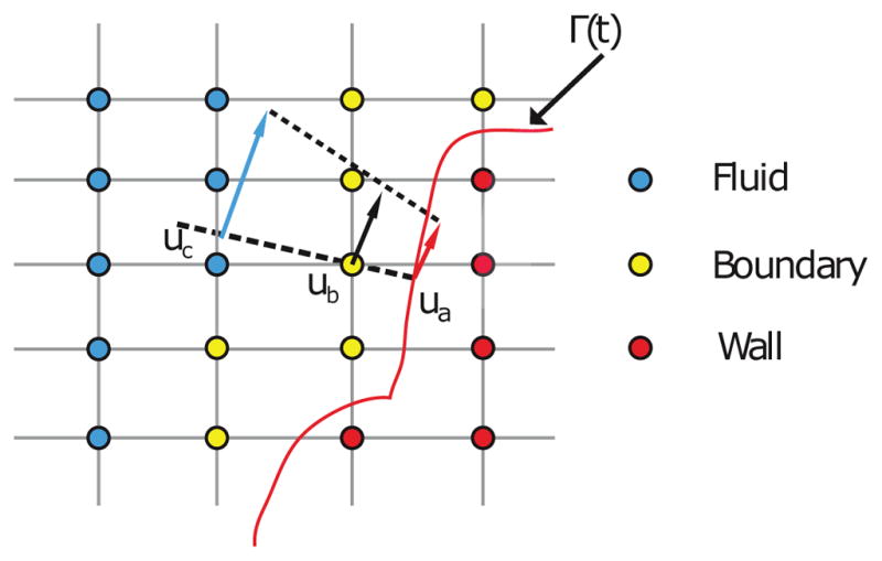
Shematic of the sharp-interface (Γ) immersed boundary method. The velocity at the immersed boundary nodes (ub) are reconstructed along the normal direction using a quadratic interpolation between velocity of wall and fluid nodes, ua and uc, respectively.
The solution of Eq. (27) with these modifications will enforce ΔUm = 0 on the boundaries. Note that the value of Um is updated on all the boundary nodes after each function evaluation during each iteration to reach the implicit solution on these nodes as well.
2.3.3. Treatment of overset grid
In order to reduce wasted nodes in a domain, caused by using immersed boundary method, we use the overset grid approach. In this approach, several sub-grids are arbitrary overlapped to discretize a complex, multi-connected flow domain. To solve the governing equations at each sub-grid, boundary conditions at the interfaces are constructed by interpolation from host sub-grid (i.e., sub-grid that contains the interface). The details of the overset-CURVIB method can be found in the recent publication by Borazjani et al. [64]. To avoid iterations in this method, all the subdomains must be solved simultaneously. Therefore, the Jacobian matrices, right-hand side vectors, and solution vectors of all subdomains are packed and solved together as follows:
| (28) |
where A(b), F⃗(b), and are the Jacobian matrix, right-hand side vector, and the corrections of contravariant velocity vector for subdomain b (b = 1,…,r, where r is the number of the subdomains), respectively. Note that in order to improve the computational time, the zeroes shown in Eq. (28) in the packed Jacobian matrix are not stored.
3. Validations and verifications
In this section, first we apply the NKM with analytical Jacobian to several numerical experiments to verify the accuracy and validate the developed solver such as: (1) Taylor-Green vortex with a distorted grid; (2) Inline oscillations of a cylinder in a fluid initially at rest; (3) The steady flow through a 90° bend; (4) The pulsatile flow through a 90° bend.
3.1. Taylor-Green vortex flow
Taylor-Green vortex is an unsteady flow of a decaying vortex with periodic boundary conditions in two directions. It has an exact analytical solution that satisfies the 2D incompressible Navier-Stokes equations [76, 77], which makes it suitable to verify the precision of the computational results. The boundary conditions are periodic boundary and the initial condition is computed based on the analytical solution at t = 0. The distorted curvilinear grid is chosen to verify the performance of the proposed methods within curvilinear coordinates. The domain size is 2π × 2π with 101 ×101 nodes. A quarter of the domain with size of π ×π is selected as a sub-domain. The lower and left sides are stretched with δ = 1.1 in x and y directions, respectively, while the upper and right sides are stretched with the similar ratio but in reverse directions. After applying a grid smoother, the sub-domain is mirrored in respect to y axis and the resulted sud-domain is mirrored in respect to x axis to obtain a periodic domain with 2π × 2π size. The geometric stretching factor is defined as follows:
| (29) |
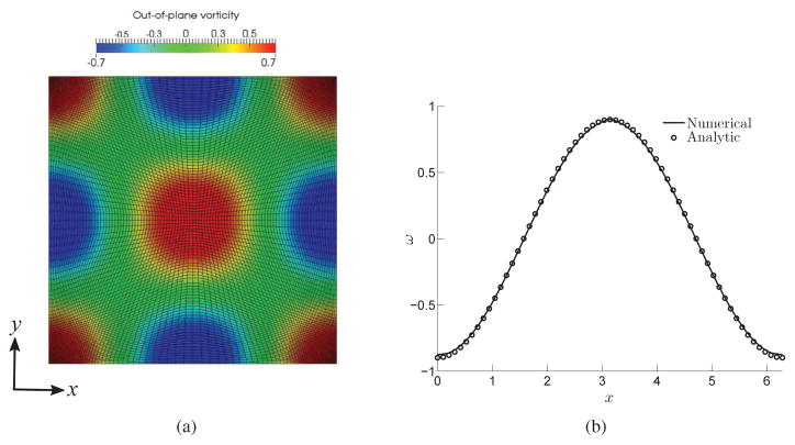
Fig. 4(a) shows the distorted curvilinear grid and the contours of the out-of-plane vorticity at a cross section of the computational domain at t = 4 (Δt = 0.01) in a simulation with Reynolds number (Re) equal to 10. Fig. 4(b) shows the out-of-plane vorticity at the mid-line parallel to the horizontal axis at t = 4. It can be observed that the numerical result (solid line) is in excellent agreement with the exact solution (circles). To quantify the order of accuracy of the solver in space and time, the error in the numerical result is calculated relative to the analytical solution for three successively finer grids and time-steps (i.e., 101 × 101 with Δt = 0.004, 251 × 251 with Δt = 0.002, and 501 × 501 with Δt = 0.001) in the distorted curvilinear mesh as follows:
| (30) |
where Nx and Ny are the number of grid points in each i and j direction, respectively, u(i,j) and v(i,j) are the numerical solutions of velocities on the (i, j) grid node, and and are the analytical solutions. Fig. 5 plots the error against the grid spacing and time step for Taylor-Green vortex problem at t = 1 and Re = 10 in log-log scale. Comparison between numerical results (circles) and a line with slope of two (solid) indicates the 2nd order accuracy of the solver.
Figure 4.
Taylor-Green vortex problem at t = 4 and Re = 10: (a) the out-of-plane vorticity contours and curvilinear grid for 2π × 2π domain; (b) the numerical result comparison of the out-of-plane vorticity at the mid-line parallel to the horizontal axis with its exact solution.
Figure 5.
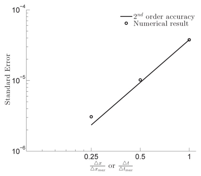
Standard error for Taylor-Green vortex flow as function of the grid spacing/time-step in log-log scale at t = 1 and Re = 10. CFL is kept the same in all test cases, i.e., .
3.2. Inline oscillations of a cylinder in a fluid initially at rest
The developed method is validated for flows with moving immersed boundaries against an experimental benchmark [78], in which a circular cylinder starts to oscillate in the horizontal direction in a fluid initially at rest. The translational motion of the cylinder is given by a harmonic oscillation:
| (31) |
where x1 is the location of the center of the cylinder in horizontal direction, f is the oscillation frequency, and Am is the oscillation amplitude. This problem is governed by two non-dimensional parameters, i.e., Reynolds number Re and Keulegan-Carpenter number KC defined as:
| (32) |
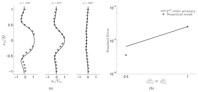
where Um is the maximum oscillation velocity, D is the cylinder diameter, and ν is the fluid kinematics viscosity. The computations are conducted at Re = 100 and KC = 5, for which both experimental and numerical results have been reported [78]. The domain size is 100D ×100D with 361 ×241 nodes in the inline (oscillatory) and transverse directions, respectively. 150 ×50 nodes are distributed uniformly in a 3D ×D box, which contains the cylinder during the oscillations. The non-dimensional time-step of Δt = 0.0167 is used for this simulation. The Neumann boundary condition is applied on the domain boundaries. Fig. 6 compares the inline velocity profiles at x1 = 0.6D for three different phase angles (ϕ = 2πf ) calculated by our method and measured by Dutsch et al. [78]. As can be observed in Fig. 6, the velocity profiles are in excellent agreement with the experimental measurements. To quantify the order of accuracy of the solver in space and time, the error of numerical results for two grids and time-steps (i.e., 361 ×241 with Δt = 0.0167, and 721 × 477 with Δt = 0.00835) are calculated relative to the numerical result of 1441 × 969 grid (finest grid) and Δt = 0.004175 based on equation 30. Fig. 6(b) plots the error against the grid spacing and time step for inline oscillations of a cylinder problem at f = 180° in log-log scale. Comparison between numerical results (circles) and a line with slope of two (solid) indicates the 2nd order accuracy of the solver.
Figure 6.
(a) The calculated inline velocity component ( ) profile at x1 = 0.6D for three different phase angles (ϕ = 2πf ) are compared with experimental results (circles) [78] (b) Standard error for velocity components as function of the grid spacing/time-step in log-log scale at f = 180° calculated based on equation 30, where uexact, vexact are velocity components of numerical results obtained using 1441 ×969 grid. CFL is kept the same in all test cases, i.e., .
3.3. Pulsatile flow through a 90° bend
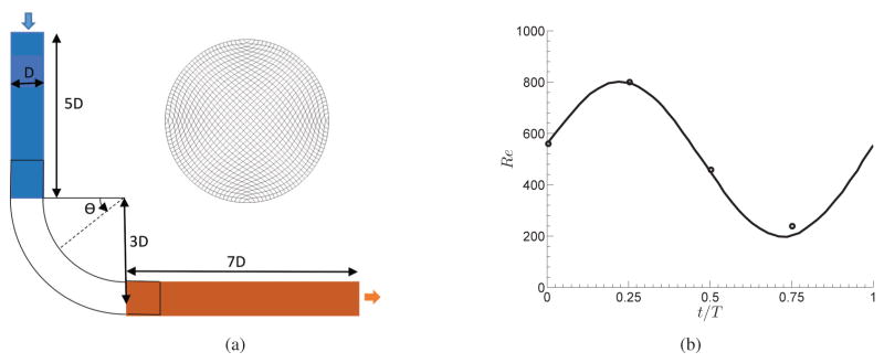
We simulate the 3D pulsatile flow through a strongly curved 90° pipe bend to validate the developed method for unsteady flows and overset grids. This test case was studied experimentally by Rindt et al. [79]. In order to validate the method with multiple overset grids, we simulate a test case with three subdomains. The geometry of the test case is shown in Fig. 7(a). Note that the geometry of the single domain is the same as the overset grid, but the whole geometry is meshed by a single curvilinear grid.
Figure 7.
(a) The geometry and grid for the 90° bend with three curvilinear overlapping grids: inlet subdomain (blue), bend subdomain (white), and outlet subdomain (orange). (b) Incoming flow waveform. Solidline: analytical non-dimensional bulk velocity waveform prescribed at the inlet of the flow domain obtained by solving the Womersley equation; Circles: the measurements of non-dimensional inlet bulk velocity from experiments [79].
As shown in Fig. 7(a), the radius of the curvature of the bend is three times of the pipe diameter (D). The inlet is placed 5D before the bend and the outlet is placed 7D after the bend. A gear pump providing a steady flow with the Reynolds number equal to 500 ( , where U is the bulk velocity, D is the pipe diameter, and ϑ is the kinematic viscosity) in conjunction with a piston pump generating sinusoidal flow waveform with Re = −300 to Re = 300 were used to generate the pulsatile flow waveform in the experiments [79]. The resulting Womersley number of the flow in the experiments were 7.8.
To generate a waveform that matches the experiment’s waveform, the inlet boundary condition is the velocity profile set from the Womersley solution of a fully developed pulsatile flow in a circular pipe as follows [37]:
| (33) |
where J0 is the zero order Bessel function of the first kind, R is the radius of the pipe, r is the radial distance from the center of the pipe, ω = 13.31 rad/s is the angular frequency of the flow oscillation, and v is the flow viscosity. The constant k is selected to be 0.375 to generate a sinusoidal flow waveform, which matches the experiment’s waveform [37, 79]. The above equation is solved using MATLAB, and the resulting solutions are stored and fed into the solver to specify the time-varying inlet flow (Fig. 7(b)). As shown in Fig. 7(b), the computed inlet Re waveform is in reasonably good overall agreement with the experimental inlet Re. The outlet boundary condition is the Neumann boundary condition. The time period of inflow oscillations, which is non-dimensionalized based on D and U, is T = 12.3. The non-dimensional time-step Δt = 0.0123 is used for the simulations. The stramwise velocity equal to one is used as the initial condition.
Grid-independency investigation is carried out by simulating pulsatile flow through the 90° bend on three different single domain grids with 25 ×25 ×91, 33 ×33 ×121, and 41 ×41 ×151 grid nodes. The streamwise velocity profiles at the plane of symmetry for different radial positions r̄ = (r – ro)/(ri – ro) (ro and ri are the outer and inner bend radius, respectively) at 0.5T time instant and θ = 45° are plotted in Fig. 8 for the three different grids. It indicates that the grid node 33 × 33 × 121 is enough to obtain a grid independent result because the streamwise velocity profile at the plane of symmetry for 33 × 33 × 121 and 41 × 41 × 151 grids are almost identical. Therefore, this grid resolution is used for comparing the numerical results to the experimental data.
Figure 8.

The streamwise velocity profiles at the symmetry plane for pulsatile flow in the 90° bend at t = 0.5T and θ = 45° for three different grids (25 × 25 × 91, 33 × 33 × 121, and 41 × 41 × 151).
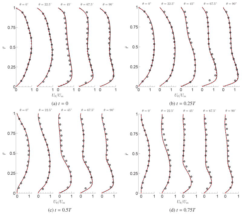
The simulated flow in the 90° bend for a single grid and overset grids with the pulsatile inlet are compared against the experimental results [79] in Fig. 9. The streamwise velocity profiles at the symmetry plane are plotted at five different locations (i.e., θ = 0°, 22.5°, 45°, 67.5°, and 90°) for four different time instants during the cycle (t = 0, 0.25T, 0.5T, and 0.75T). Note that to test the overset method, three overlapping grids as shown in Fig. 7(a) (33 × 33 × 24, 33 × 33 × 78, and 33 × 33 × 38 grids for the inlet, middle, and the outlet subdomains, respectively) are used. As observed from Fig. 9, the computational results are in good overall agreement with the experimental results. The maximum discrepancy is at t = 0.75T, where the largest deviation from experimental inlet waveform from Womersly inlet waveform exists (Fig. 7(b)). The solutions on the overset grid are in excellent agreement with the single grid results.
Figure 9.
Pulsatile flow through a 90° bend. The calculated streamwise velocity profiles at the plane of symmetry for a single grid (solid) and overset grid (dashed) are compared with experimental results (circles) at different time instants. r̄ = (r – ro)/(ri – ro) (ro and ri are the outer and inner bend radius, respectively), Uθ is the streamwise velocity at the symmetry plane, and Um is the maximum streamwise velocity at the symmetry plane at t/T = 0 and θ° = 0
3.4. Steady flow through a 90° bend
We simulate 3D steady flow through a strongly curved 90° pipe bend to validate and investigate the computational performance of the developed method. This test case was studied experimentally by Bovendeerd et al. [80]. Note that the geometry and grid resolution used for comparing the results against the experimental data, for both the overset and the single grid, are the same as those in pulsatile flow through a 90° bend (Fig. 7(a)). In this test case, the inlet , where U is the bulk velocity, D is the pipe diameter, and ϑ is the kinematic viscosity [80] with a fully developed (parabolic) velocity profile boundary condition at the inlet, and the Neumann boundary condition at the outlet. The non-dimensional time-step of Δt = 0.02 is used for these simulations. The stramwise velocity equal to one is used as the initial condition.
The simulated flow in the 90° bend with the steady inlet, for both single and overset grids, is validated against the experimental data [80]. The streamwise velocity profiles at the plane of symmetry for numerical and experimental results are plotted at different angles (θ = 0°, 23.4°, 58.5°, and 90°) in the bend in Fig. 10. As observed, the calculated velocity profiles for both single and overset grids are in an excellent agreement with the experimental measurements.
Figure 10.
Steady flow through a 90° bend. The calculated streamwise velocity profiles at the plane of symmetry for a single grid (solid) and overset grid (dashed) are compared with experimental results (circles). r̄ = (r – ro)/(ri – ro) (ro and ri are the outer and inner bend radius, respectively), Uθ is the streamwise velocity at the symmetry plane, and Um is the maximum streamwise velocity at the symmetry plane at θ° = 0.
4. Computational performance
The test cases in section 3 are used to investigate different numerical aspects of the developed methods including comparing the computational time and convergence rate of the analytical Jacobian with AD, MF, and FPRK, grid topology and Reynolds number effect on computational time, as well as the parallel computing efficiency. We investigate the analytical Jacobian in two forms: First, the full form of the analytical Jacobian (FJ); Second, only the diagonal part of the analytical Jacobian (DJ).
4.1. Computational time and convergence rate
The steady flow through a 90° bend (3.4) is used to investigate the computational time and convergence rate among DJ, FJ, AD, MF, and FPRK. For each method, at each iteration, the residual is computed based on the l2-norm of the right-hand side of Eq. (14). The residual at iteration k is normalized by the residual of the first iteration, which is referred to as the relative residual hereafter. The convergence criteria is set based on the relative residual less than 10−3. This convergence criteria was found to be sufficient to obtain excellent agreement against experimental and numerical data for different benchmarks such as Taylor-Green vortex and the pulsatile/steady flow in the 90° bend. It should be noted that the problem reaches to the steady state at t = 1.23, i.e., all presented results are calculated in the transient regime. MF without preconditioner only converged on the coarsest grid. This is because MF requires Krylov subspace method as an iterative technique to solve the Newton equation at each iteration (k). While the convergence of Krylov methods depends on the condition number [23], i.e., the MF convergence degrades for Jacobians with large condition numbers. The Jacobian condition number is defined as the absolute value of maximum eigenvalue of the Jacobian matrix divided by the absolute value of minimum eigenvalue, which can be approximately extracted by solving the linear Newton equation by Krylov subspace method. The approach is to compute the eigenvalues of the orthogonal projection of the Jacobian onto the Krylov subspace in the Arnoldi algorithm [81]. The Jacobian condition number increases accordingly by increasing the grid size [23], as shown in Fig. 11 which plots the Jacobian condition number normalized relative to the smallest one for different grid sizes at initial time. Because of the high condition number on fine grids (Fig. 11), the MF without preconditioner converges only on the coarsest grid. To resolve this issue, a preconditioner is formed for MF. We used analytical Jacobian to form a preconditioner for MF because forming a preconditioner from the Jacobian computed numerically is quite expensive (similar to AD) and defeats the purpose of the matrix-free. The Jacobi preconditioner is used in the NKMs.
Figure 11.
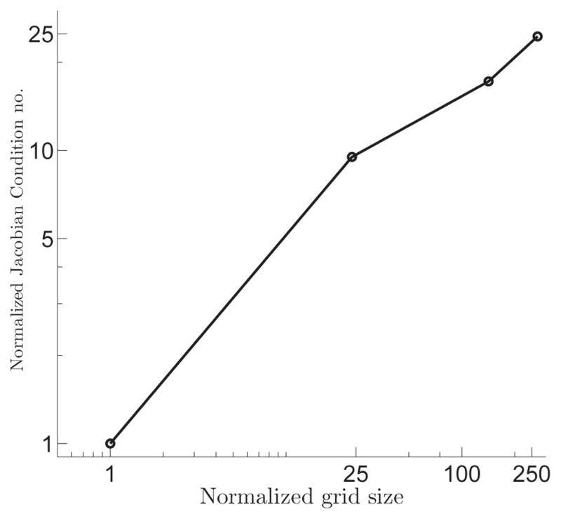
The normalized Jacobian condition number a function of normalized grid size for simulation of steady flow in the 90° bend at initial time instant.
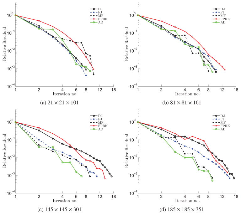
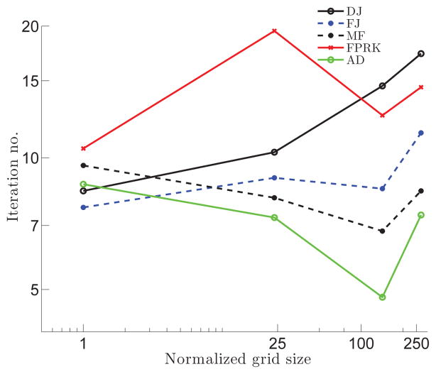
Fig. 12 plots the relative residual at non-dimensional t = 0.5 versus the number of iterations for different methods and grid sizes. As observed in Fig. 12(a) and (b), on coarse grids, there is no significant difference in the decrease of the relative residual among FJ, DJ, MF, and AD. MF has a slightly sharper relative convergence slope than FJ. AD’s relative residual slope is noticeably sharper than FJ for finer mesh cases (Fig. 12(c) and (d)). The primary reason for this trend is that the Jacobian in AD is exact, i.e., without any simplifications. Consequently, solving the Newton equations with an almost exact Jacobian at each iteration results in a more accurate estimation of the Newton equations solution. Thus, the number of the Newton iterations needed for convergence (kmax) at each time-step decreases. To illustrate this point, Fig. 13 presents the average iterations required for convergence on different grids. The average iterations is the average of kmax in all time-steps from non-dimensional t = 0 until t = 1. It can be observed that the average iterations for AD is about 18% less than MF, which is about 19% less than FJ, which is about 30% less than DJ in all grid sizes, except on the coarsest grid on which the values are quite close. The number of iterations of the FPRK is higher than all NKMs, except on the finest grid on which it is similar to DJ. Nevertheless, the number of iterations for convergence is not the only parameter that determines the computational time.
Figure 12.
Convergence of the Newton Eq. (14) at non-dimensional t = 0.5 for simulation of steady flow in the 90° bend for different methods and grid sizes. The relative residual of the right-hand side of the Newton Eq. (14) is plotted for each iteration. The iterations are considered converged when the relative residual becomes less than 10−3. The residual of Newton methods at the first iteration is 0.235, 0.188, 0.185, and 0.178 in (a), (b), (c), and (d), respectively and the residual of FPRK at the first iteration is 0.112, 0.105, 0.098, and 0.095 in (a), (b), (c), and (d), respectively.
Figure 13.
The average of kmax (the iterations required for convergence at each time-step) in all time-steps from non-dimensional t = 0 until t = 1 for steady flow in the 90° bend.
The performance of the developed methods in terms of the computational time is investigated by comparing FJ, DJ, AD, MF, and FPRK. The computational time is defined as the sum of all the time spent on solving the momentum equation (not the pressure Poisson Eq. (9)) at each time-step until non-dimensional t = 1 is reached. Therefore, the computational time depends on (1) the number of the time-steps to reach t = 1; and (2) the CPU time of each time-step. The number of time-steps is determined by the optimum CFL number ( , where U is the inlet average velocity, Δt is the optimum time-step defined in Appendix B, and hmin is the minimum grid size of all directions of the curvilinear mesh), whereas the CPU time of each time-step depends on the number and cost of the Newton or fixed-point iterations to converge at each time-step.
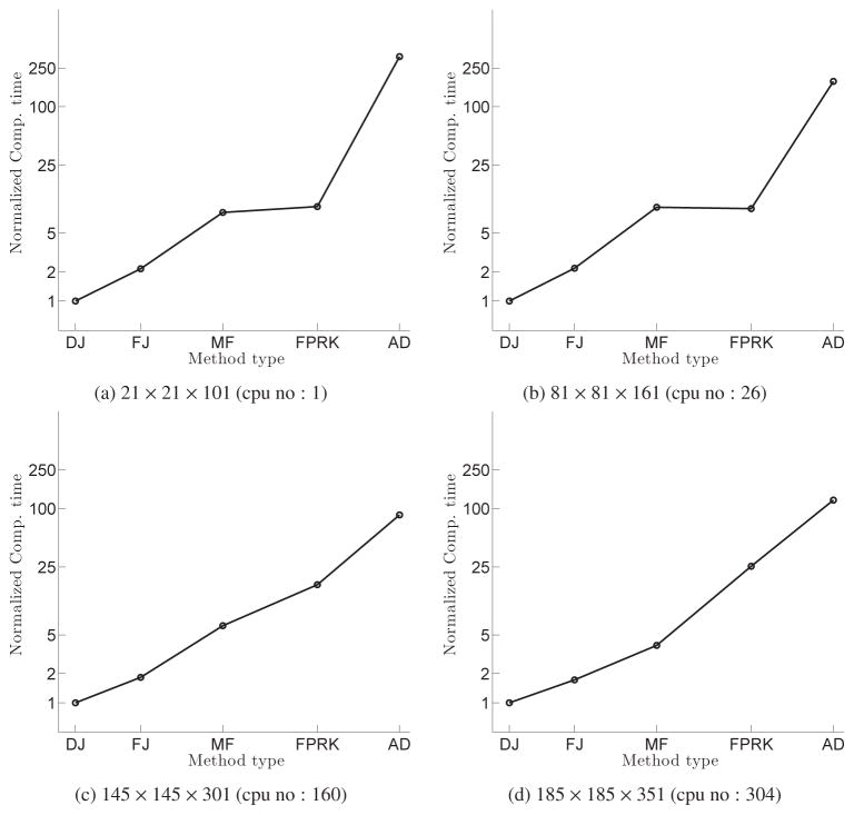
Fig. 14 presents the computational time of the stated methods on four different grids (i.e., 21 × 21 × 101, 81 × 81 × 161, 145 × 145 × 301, and 185 × 185 × 351). Note that grid sizes are normalized relative to the minimum grid size, which is 21 × 21 ×101, and the computational time is normalized by the minimum computational time. To be consistent, the flow for a given grid is simulated on a similar number of CPUs for all methods. The simulations were carried out on the parallel computing cluster, Nami, with 28 nodes, each node containing two 8-core (Magny-Cours) AMD 2.0 GHz with 2GB RAM per core and QDR infiniband. All the simulations in this study were carried out on this parallel computing cluster (Nami).
Figure 14.
Normalized computational time as function of the method type from initial time instant until t = 1 for steady flow in the 90° bend for different grids.
It can be observed in Fig. 14 that AD spends 13.8 to 40.09 times more computational time than MF, which spends 2.72 to 4.24 times more computational time than FJ, which spends 1.72 to 2.15 times more computational time than DJ depending on the grid (size) for solving the momentum equation. Considering that the time-step size (consequently, the number of time-steps to reach t = 1) for AD, FJ, and DJ is similar on a specific grid, the question is why the computational time of DJ is smaller than FJ, and both of them smaller than AD, which converges in less iterations than all the other methods (Fig. 12). There are two main reasons for this trend: First, forming the numerical Jacobian in AD involves many function evaluations which consumes more computational time; Second, more components in the Jacobian (A) results in more expensive solutions of the Newton Eq. (14) at each iteration (k). Our experience shows that for this particular example, AD, FJ, and DJ need about 10, 3, and 1 FGMRES iterations to converge at each Newton iteration (k), respectively. The main reason for higher computational time of MF relative to FJ and DJ is the higher FGMRES iterations to converge at each Newton iteration, similar to AD (approximately 6 for this particular example).
Regardless of the mesh size, FJ and DJ require less computational time than FPRK, especially on finer grids (Fig. 14). There are two main reasons for this behavior: First, FJ and DJ generally need less iterations to converge than FPRK on the same grid (Fig. 13); Second, FJ and DJ converge at a larger time-step (larger optimum CFL) than fixed-point methods because of its semi-implicit nature, i.e., can reach t = 1 with lower number of time-steps. Fig. 15 presents the optimum CFL used in the simulations for each method and each grid size. It can be observed in Fig. 15 that the optimum CFL number decreases as grid size increases for FPRK, while it stays almost the same for DJ, FJ, and AD. Note that there is a trade-off between the time-step size and the number of the Newton iterations needed for convergence. By increasing the time-step size, the number of Newton iterations required for convergence increases because the initial condition for the Newton iteration, i.e., previous time-step solution, moves away from the solution as the time-step increases for the results presented in this section. We selected the optimum time-step size to minimize the computational time. The effect of time-step (CFL number) is further investigated in Section 4.4.
Figure 15.
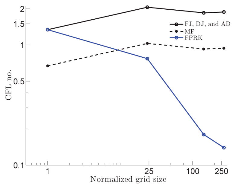
Optimum CFL number as function of normalized grid size for steady flow in the 90° bend for different method types.
4.2. Grid topology effect on computational time
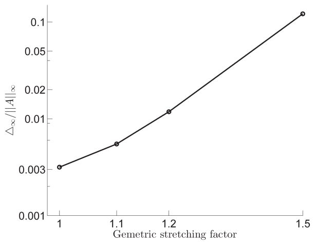
In the derivation of the analytical Jacobian, we made the simplifying assumption that the grid properties are locally constant to avoid Christoffel symbols and simplify the formulation (Section 2.3.1). This assumption is exactly satisfied on uniform grids, but creates deviations between the analytical Jacobian and the exact Jacobian on non-uniform grids. To investigate the effect of grid topology and non-uniformity on the computational time, the Taylor-Green vortex (Section 3.1) with Re = 10 is investigated. A quarter of the domain with size of π×π is selected as a sub-domain. The left side of the sub-domain is uniformly discretized and the lower side of the sub-domain is divided into four segments and stretched at each segment individually in order to keep minimum and maximum grid size in a reasonable range while enabling us to produce high grid stretching. It should be noted that each segment is stretched in reverse direction of that in neighbor segment(s). After applying a grid smoother, the sub-domain is mirrored in respect to y axis and the resulted sud-domain is mirrored in respect to x axis to obtain a periodic domain with 2π × 2π size. The geometric stretching factor is calculated from equation 29. Fig. 16 shows maximum difference between FJ and the AD Jacobian with different grid topologies (uniform, δ = 1.1, 1.2, and 1.5, where δ is the geometric stretching factor) and the same grid size (101 × 101) at Re = 10 from initial time instant until t = 1. The difference is calculated based on the infinity norm of the subtraction of the AD Jacobian from FJ, denoted as Δ∞, normalized by the infinity norm of the AD Jacobian, denoted as ||A||∞. As can be observed from Fig. 16, the normalized difference is negligible in uniform and even δ = 1.1 grids (less than 1%). By increasing the stretching factor, the normalized difference between FJ and AD Jacobian increases. However, the stretching factor should be bounded for maintaining the order of accuracy, e.g., the stretching error is highly increased from δ = 1.0083 to 1.0456 in [82]. It should be noted that the normalized difference between DJ and the diagonal of AD Jacobian is negligible for all grid topologies, i.e., the difference in Fig. 16 is mainly because of the off diagonal elements of the Jacobians.
Figure 16.
Maximum difference between FJ and the AD Jacobian in Taylor-Green vortex flow with different grid topologies and the same grid size (101 × 101) at Re = 10 from initial time instant until t = 1. The difference is calculated based on the infinity norm of the subtraction of the AD Jacobian from FJ and normalized by the infinity norm of the AD Jacobian.
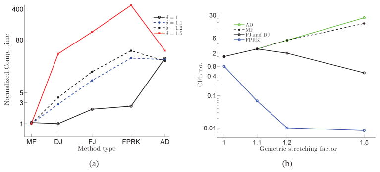
The computational time is calculated as the summation of all the time spent on solving the momentum equation at each time-step until the non-dimensional t = 1 is reached. Computational time increases with δ in all methods, e.g., the ratio of computational time with δ = 1.1, 1.2, and 1.5 to that with uniform mesh is 1.44, 1.83, and 5.23, respectively in MF. However, the amount of increase is not the same between methods. To compare the computational time between methods as delta increases, Fig. 17(a) presents the normalized computational time of DJ, FJ, MF, FPRK, and AD methods on three different grid topologies (i.e., δ = 1, 1.1, 1.2, and 1.5) with the same grid size (101 × 101). The computational time is normalized by the minimum computational time obtained among methods on each grid topology. The computational time of MF is less than all other methods for all mesh topologies except the uniform mesh, which MF and DJ’s computational time are approximately equal. The ratio of DJ’s computational time to MF’s computational time increases from 0.94 to 2.77, 3.94, and 38.79 by increasing the stretching factor from 1 to 1.1, 1.2, and 1.5, receptively. Regardless of the mesh topology in Fig. 17(a), FJ spends more computational time than DJ for solving the momentum equation in all mesh topologies. The computational time ratio of AD to that of DJ decreases by increasing stretching factor, i.e., AD’s performance in comparison to the DJ, FJ, and FPRK degrades more slowly as the stretching factor is increased. However, because of high expense of full Jacobian formation and solving it, it still takes more computational time than DJ. The computational time of FPRK is higher in comparison to DJ in all mesh topologies. The ratio of FPRK’s computational time to DJ’s computational time increases from 2.5 to 11.15, 11.54, and 12.62 by increasing the stretching factor from 1 to 1.1, 1.2, and 1.5, receptively.
Figure 17.
Taylor-Green vortex flow with different grid topologies and same grid size (101 × 101) at Re = 10 for different method types: (a) computational time from initial time instant until t = 1 normalized by the fastest of them on each grid; and (b) optimum CFL number.
The main reason for the above trends is the CFL number. Fig. 17(b) presents the optimum CFL used in the simulations for each method and mesh topology. The degrade of the optimal time-step because of the rapid change in grid for MF (Δt = 0.1 and 0.05 for δ = 1 and 1.5, respectively) is much smaller than FJ and DJ (Δt = 0.1 and 0.0015 for δ = 1 and 1.5, respectively). Therefore, the rapid change in grid does not decrease, but increases the optimum CFL for MF, in contrast to DJ and FJ. This is the consequence of the fact that by increasing the stretching factor, the normalized difference between numerical and analytical Jacobian increases as well. The similar trend can be observed for AD. However, AD requires considerably more computational time to compute the product of Jacobian vector in comparison to MF since AD forms the Jacobian and then multiply it by vector, in contrast to MF. The CFL number decrease also cause faster degrade in FPRK’s computational performance in comparison to DJ. As observed, NKM’s optimum CFL is larger than FPRK regardless of mesh topology, which indicates lower number of time-steps (lower cost) to reach t = 1. In fact, for FPRK, in contrast to NKMs, CFL drastically decreases from 0.8 on a uniform grid to 0.000025 in δ = 1.5.
4.3. Reynolds number effect on computational time
The inline oscillations of a cylinder in a fluid initially at rest (Section 3.2) in three-dimension is used to investigate the Reynolds number effect on computational time among FJ, DJ, AD, and FPRK. The domain size is 100D×100D×D with 361×241×51 nodes in the inline (oscillatory), transverse, and cylinder’s height directions, respectively. Fig. 18(a) presents the normalized computational time of the stated methods for Re = 100, 1000, and 10000. The computational time is calculated as the summation of all the time spent on solving the momentum equation at each time-step until non-dimensional t = 1 is reached and is normalized by the minimum computational time at each Re. It can be observed in Fig. 18(a) that AD’s computational time is 36.52 to 52.65 times higher than FJ, which is 2.33 to 2.55 times higher than DJ, which is 1.38 to 9.2 times less than MF depending on the Reynolds number for solving the momentum equation. Computational time correlates with Re in DJ, FJ, and AD, e.g., the ratio of computational time with Re = 1000 and Re = 10000 to that with Re = 100 is 1.69 and 2.47, respectively in DJ. This is probably because increasing Re decreases the diagonal dominance of the Jacobian because the viscous terms in the diagonal are proportional to 1/Re (Appendix A). Diagonally dominant matrices are well-conditioned and converge faster [83]. In contrast, the computational time in MF decreases by increasing Re, i.e., the ratio of computational time with Re = 100 and 1000 to that with Re = 10000 is 2.7 and 1.05, respectively. This is because the normalized condition number of Jacobian, calculated similar to section 3.4, decreases by increasing Re, i.e., the normalized condition number of Re = 100 and 1000 to that of Re = 10000 is approximately 2.46 and 1.05, respectively, which leads to the less number of Newton iterations needed for convergence in higher Re (kmax ≈ 9, 3, and 3 for Re = 100, 1000, and 10000, respectively). This does not apply for DJ and FJ, e.g., kmax ≈ 6, 7, and 10 for Re = 100, 1000, and 10000, respectively. Although AD benefits from the low number of Newton iterations at each time steps in Re = 1000 and Re = 10000(k ≈ 3) similar to MF, the high computational cost of Jacobian formation in AD defeats this advantages, in contrast to MF.
Figure 18.
Inline oscillations of a cylinder in a fluid initially at rest in three-dimension at Re = 100, 1000, and 10000 for different method types: (a) computational time from initial time instant until t = 1 normalized by the fastest of them at each Re; and (b) optimum CFL number.
The computational time of FPRK increases by rising Re form 100 to 1000 and remains constant by rising Re form 1000 to 10000. FPRK’s computational time is higher than DJ at all Reynolds numbers while the ratio of FPRK computational time to DJ computational time decreases by increasing Re from 7 to 3.1. The main reason for the observed trends in Fig. 18(a) is the CFL number. Fig. 18(b) presents the optimum CFL used in the simulations for each method and Re. It can be observed that DJ’s optimum CFL is larger than FPRK (Fig. 18(b)). However by increasing Re the optimum CFL in DJ decreases, in contrast to FPRK which stays constant.
4.4. Convergence region: time-step effect on computational time
If the initial solution is far from the exact solution, the Newton method might fail to converge [39, 38]. The initial condition for the Newton method in here is the solution at the previous time instant. Therefore, the smaller the time-step, the closer the initial solution to the exact solution. The pulsatile flow through a 90° bend (Section 3.3) is used to investigate the time-step effect on computational time DJ, MF, FJ, and AD. The computational time is the sum of all the time spent on solving the momentum equation at each time-step until non-dimensional t = 1 is reached. The computational time is normalized by the minimum computational time for each method. Increasing the Δt will reduce the number of time-step to reach t = 1 but will require more Newton iterations because the initial solution of the Newton method has move away from the exact solution, i.e., there is a trade-off between the time-step size and the number of the Newton iterations needed for convergence. There is an optimum time-step size at which the computational time is minimum. It is noted that Δt is restricted with implemented pressure-velocity coupling algorithms, i.e., fractional-step, to conserve the accuracy of method and practically cannot be increased without bounds. Fig. 19 presents the normalized computational time of the stated methods for 145 × 145 × 301 grid on 160 CPUs using different time-step sizes. It is observed in Fig. 19 that the optimum time-step for DJ, FJ, and MF is similar (Δt = 0.01) and that for AD is Δt = 0.005. The optimum time-step size in FPRK is the largest Δt at which FPRK converges and in this case it is 0.001 (CFL=0.185). The increase in the time-step did not increase the computational time required for solving the Poisson equation.
Figure 19.
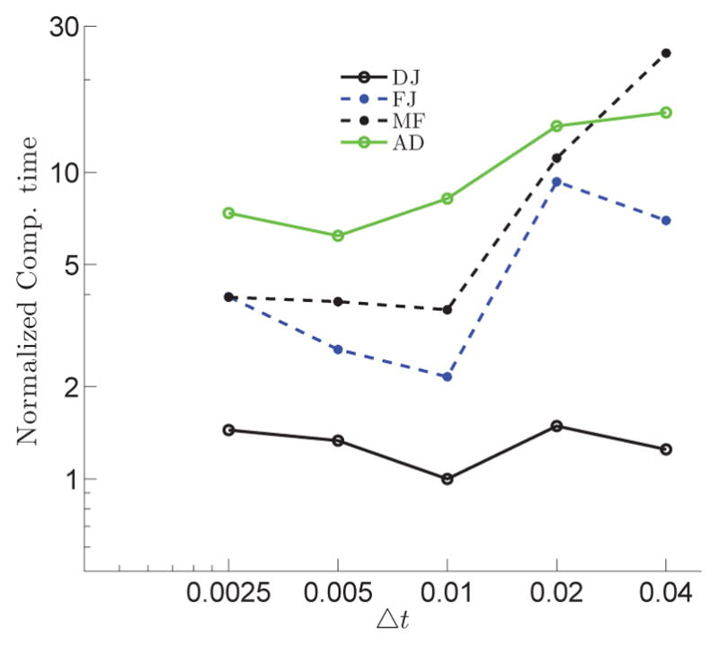
Computational time as function of time-step from initial time instant until t = 1 for pulsatile flow in the 90° bend for different grids. The computational time is normalized by the minimum computational time for each method.
4.5. Parallel performance
For further examination of the proposed methods, steady flow in the 90° bend (3.4) is used to demonstrate parallel performance of the analytical Jacobian for NKM. Parallel efficiency and speed up for strong-scaling based on the computational time on the smallest CPU number (Nmin) is defined as follows:
| (34) |
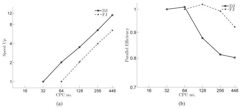
where T(N) denotes computational time on N CPUs. Nmin are 32 and 64 for DJ and FJ, respectively. We cannot run simulations on less than Nmin number of CPUs because of memory requirements. The computational time is computed by the sum of all the time spent on solving the momentum equation for 10 time-steps from initial time instant, in which each time-step includes 10 Newton iterations (100 Newton iterations in total). Because of the memory requirements associated with the forming Jacobian containing more non-zero components in FJ, DJ requires less memory than FJ. Fig. 20 plots parallel efficiency and speed-up for FJ and DJ on the single grid (217 × 217 × 437, which is about 20 million nodes) on a different number of CPUs (32, 64, 128, 256, and 448). As shown in Fig. 20, the developed methods present excellent parallel efficiency and scale well with increasing CPU. The cache effect [84] can be observed on 64 and 128 number of CPUs for DJ and FJ, respectively, which increases the efficiency to slightly over one.
Figure 20.
Strong-scaling parallel performance investigation: (a) Speed up; (b) Efficiency for steady flow in the 90° bend on 217 × 217 × 437 grid dimension.
The same example is used for weak-scaling (grid size per CPU remains almost constant) investigation of speed up ( ) as shown in Fig. 21. The 16, 144, 240, and 448 number of CPUs are used for solving the same problem on 73 × 73 × 137, 149 × 149 × 297, 173 × 173 × 368, and 217 × 217 × 437 grid dimensions, respectively. Note that speed up is calculated based on the computational time of the numerical example on the coarsest grid (73 × 73 × 137) on the smallest CPU number (16). As shown in Fig. 21, the developed methods scale well with increasing CPU and grid size.
Figure 21.
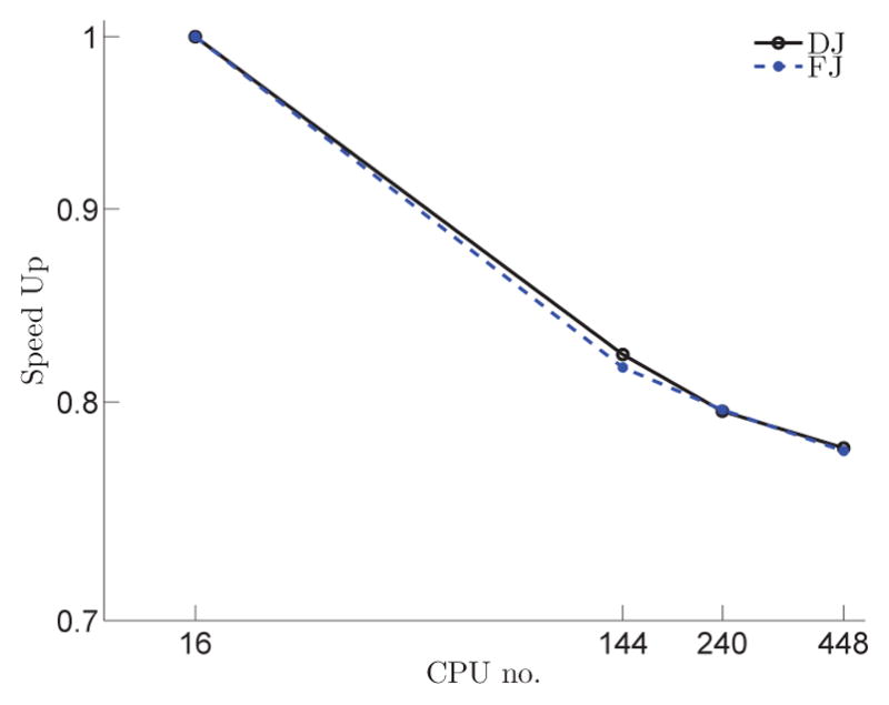
Weak-scaling parallel speed up investigation for steady flow in the 90° bend.
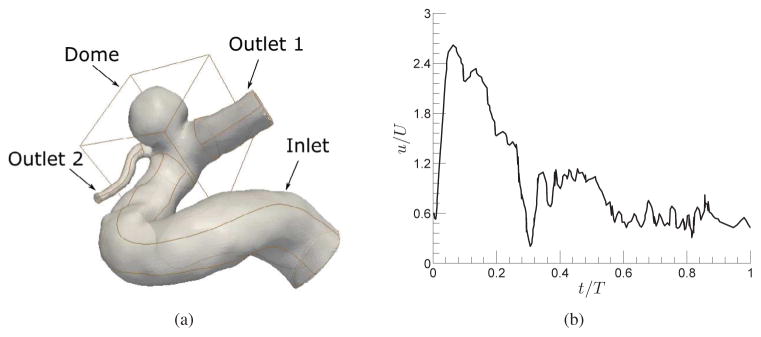
4.6. Performance on a problem with both immersed boundary and overset grids
An intracranial aneurysm is simulated to show the ability of the developed methods to handle complex geometries with multiple overset grids and immersed boundaries. This geometry is reconstructed from three-dimensional rotational angiography of a human subject [85]. It is meshed by three body-fitted curvilinear meshes for inlet (with 61 × 61 × 293 grid nodes) and two outlets (with 33 × 33 × 145 and 45 × 45 × 73 grid nodes) and one fine uniform mesh for the dome (with 201 × 201 × 201 grid nodes) as shown in Fig. 22(a). The geometry of the dome is placed as an immersed boundary in the domain with the uniform grid. The Neumann boundary condition is applied on the outlet boundaries, and the flux of each outlet is determined based on the principle of optimal work [86, 87]. The inlet boundary condition is a pulsatile velocity waveform (Fig. 22(b)) [88]. The non-dimensional time period (T) of the inflow waveform is equal to 16.67, which is determined based on the 75 beats per minute heart rate (0.8s), the aneurysm inlet diameter, and the bulk velocity. The non-dimensional time-step Δt = 0.004 is used for this problem, and the Reynolds number is 145 ( , where U is the bulk inlet velocity, D is the aneurysm inlet diameter, and ϑ is the blood kinematic viscosity). The NKM with DJ and FJ could successfully converge in approximately 5 Newton iterations at each time-step. Fig. 23 presents the evolution of the non-dimensional out-of-plane vorticity at a plane in the dome of the intracranial aneurysm at various time instants during a cycle. This numerical simulation has been carried out for a cycle on 96 CPUs. DJ is 1.24, 1.53, and 3.36 times faster than MF, FJ, and FPRK, respectively, in solving the momentum equation. The method to solve the momentum equation does not affect the required to solve the Poisson equation, i.e., the computational time to solve the Poisson equation is the same for all DJ, FJ, and FPRK. Therefore, DJ is only 1.15, 1.34, and 2.51 times faster than MF, FJ, and FPRK, respectively, in the overall solution (including both momentum and Poisson equations). As mentioned before, DJ is 9 to 25 times faster than FPRK for the simulations of the flow in the 90° bend. This value reduces to 3.36 in an intracranial aneurysm simulation because the time-step size is the same (non-dimensional Δt = 0.004) in all methods, i.e., DJ, FJ and FPRK. FPRK could converges with a Δt as large as the Newton method on the uniform grid. Therefore, DJ only takes advantage of converging in less iterations rather than both iterations and time-steps. In this simulation, similar to the flow in the 90° bend, DJ is faster than FJ. There is a trade-off between completeness of the analytical Jacobian and the Newton iterations required for convergence (i.e, the Newton equations with more complete analytical Jacobian converge in less Newton iterations, although it increases the computational cost because of increasing the FGMRES iterations and forming analytical Jacobian with more components). This simulation clearly show that using analytical Jacobian decreases the computational cost relative to fixed point and other NKMs such as AD and MF.
Figure 22.
(a) An intracranial aneurysm geometry consists of three curvilinear meshes for inlet, outlet1, outlet2, and a single immersed boundary at dome. (b) Pulsatile inlet flow for an Aneurysm where T is the non-dimensional time period of inflow oscillations and U is the median velocity.
Figure 23.
Evolution of the non-dimensional out-of-plane vorticity at a plane in the dome of the intracranial aneurysm at various time instants during a cycle; (a) t/T = 0.03, (b) t/T = 0.15, (c) t/T = 0.25, (d) t/T = 0.3, and (f) t/T = 0.75. The schematic of the flow direction is shown in (a).
5. Discussions and conclusions
Explicit and semi-implicit methods, e.g., FPRK, are computationally expensive to simulate flows involving complex geometries with moving boundaries mainly because of their severe time-step restriction and low convergence rates. We have developed a novel analytical Jacobian for the Newton-type implicit method in combination with Krylov subspace methods in order to enhance both the time-step size and the convergence rate. These methods were added to the previous framework [63, 64, 75] in which the Navier-Stokes equations were solved using FPRK and MF without a preconditioner. The analytical Jacobians were modified to work with the immersed boundary and overset grid methods to be able to handle complex geometries such as an intracranial aneurysm. Analytical Jacobian were validated and verified against well-known benchmarks with overset grids, moving immersed boundaries, pulsatile inlet flows, and steady flow on a curvilinear coordinates. Furthermore, analytical Jacobian presents the 2nd order accuracy in space and time and excellent parallel efficiency (more than 80–90%). Finally, the analytical Jacobian was used as a preconditioner for the MF to improve its performance.
We build the Jacobian with four techniques: (1) MF, in which no Jacobian-matrix is formed; (2) AD, in which the Jacobian is formed completely; (3) FJ, in which some simplifications are applied to derive it analytically; and (4) DJ, in which FJ is approximated by its diagonal part. We have developed DJ to investigate if we can further reduce the computational time in comparison to FJ, considering that there is no agreement in literature on the superiority of one over the other in term of the computational time. Wright et al. [71] implemented lower-upper symmetric Gauss-Seidel method for the simulation of viscous flows and concluded that, for different Reynolds numbers, grid topologies, and grid sizes, full Jacobian achieves convergence faster than the diagonal Jacobian in terms of computational time. The diagonal Jacobian in aforementioned study is simply formed by a spectral approximation. The full and/or diagonal Jacobian (formed by the spectral approximation) are used as preconditioner for Krylov methods to solve Navier-Stokes equations [89]. Ekici et al. [89] stated that for time-accurate computations, hybrid of diagonal and full Jacobian method produces the best performance. Similarly Radhakrishnan and Hindmarsh [72] found that diagonal Jacobian (computed by neglecting all off-diagonal elements of the full Jacobian formed by automatic differentiation scheme) for Newton iteration for solving ordinary differential equations is not as fast as the full Jacobian. In contrast, Waziri et al. [70] stated that the diagonal Jacobian for nonlinear equations is faster than the full Jacobian (computed by automatic differentiation method). Therefore, the superiority of one over the other in terms of the computational time depends on the set of equation and the solver. For Navier-Stokes equations on staggered grids, based on our results, DJ is always faster than FJ.
We have investigated effect of Re, grid topology, and grid size on their performance in terms of computational time. The computational time ratio of FJ over DJ decreases by the increase of grid size (from 2.15 on coarse grid to 1.72 on fine grid) for steady flow in the 90° bend, increases by the increase of stretching factor (from 2.13 when δ = 1 to 3.12 when δ = 1.5) for Taylor-Green vortex problem, and slightly decreases by the increase of Re (from 2.55 with Re = 100 to 2.33 with Re = 10000) for the inline oscillations of a cylinder.
AD is the most expensive method among the developed methods in most of the simulations. There are two main reasons for high expense of AD despite its high convergence rate (especially on fine grids): First, the numerical Jacobian formation involves many function evaluations which consumes more computational time; Second, the Jacobian with more components leads to more expensive solutions of the Newton Eq. (14) at each iteration (k). However, AD’s performance improves in term of computational time when there is a rapid change in the grid because of higher optimum CFL in comparison to FPRK, FJ, and DJ (Fig. 17(b)).
To the best of our knowledge, this is the first study that different Newton methods are compared with fixed point method in terms of computational time on a real problem. DJ and FJ are faster than FPRK in all our simulations. There are two main reasons for this behavior: First, DJ and FJ generally need less Newton iterations to converge than FPRK on the same grid; Second, FJ and DJ’s optimum CFL is larger than fixed-point methods because of its semi-implicit nature. The computational time ratio of FPRK over DJ increases by the increase of grid size (from 9.37 on coarse grid to 25.4 on fine grid) for steady flow in the 90° bend, increases by the increase of stretching factor (from 2.5 when δ = 1 to 12.6 when δ = 1.5) for Taylor-Green vortex problem, and decreases by the increase of Re (from 7.01 with Re = 100 to 3.1 with Re = 10000) for the inline oscillations of a cylinder.
It is observed that MF without preconditioner converges only on the coarsest grid for steady flow in the 90° bend because the condition number of the Jacobian increases as the grid is refined (Fig. 11). Preconditioners for MF is formed using the analytical Jacobian since forming the Jacobian numerically is quite expensive (similar to AD). MF is the only method which can compete with performance of DJ in terms of the computational time on solving the momentum equation among all other methods (MF, FJ, AD, and FPRK). In fact, the computational time of DJ is 2.77, 3.94, and 38.79 times higher than MF in Taylor-Green vortex problem with stretching factor of 1.1, 1.2, and 1.5, receptively. In addition, the computational time of MF is slightly higher than DJ (1.38 times) in the inline oscillations of a cylinder with Re = 10000. However, MF’s computational time is 3.9 to 9.22 times higher than DJ’s for steady flow in the 90° bend depending on grid sizes and this ratio is 9.22 and 2.11 for the inline oscillations of a cylinder with Re = 100 and 1000, respectively. The computational time ratio of MF over DJ decreases by the increase of grid size (from 8.16 on coarse grid to 3.99 on fine grid) for steady flow in the 90° bend, decreases by the increase of stretching factor (from 1.05 when δ = 1 to 0.026 when δ = 1.5) for Taylor-Green vortex problem, and decreases by the increase of Re (from 9.22 with Re = 100 to 1.38 with Re = 10000) for the inline oscillations of a cylinder.
It was shown herein that using a simplified analytical Jacobian in combination with Krylov subspace method can lead to a computationally efficient implicit method for solving Navier-Stokes equations. The results of this study can be used to improve the performance of other numerical techniques for solving Navier-Stokes equations. It should be noted that the computational times calculated in this study are restricted to our implementations of the different methods.
Acknowledgments
This work was partly supported by National Institute Of Health (NIH) grant R03EB014860, National Science Foundation (NSF) CAREER grant CBET 1453982, and the Center of Computational Research (CCR) of University at Buffalo. We are grateful to Professor Hui Meng for providing us with the geometry of the intracranial aneurysm. We thank Matthew Knepley, Ph.D., and Jed Brown, Ph.D., from PETSc for their helpful discussions and guidelines.
Nomenclature
- NKM
Newton-Krylov method
- AD
Automatic differentiation, i.e., NKM, in which Jacobian is formed by automatic differentiation method
- FJ
Full Jacobian, i.e., analytical Jacobian, in which whole components are considered
- DJ
Diagonal Jacobian, i.e., analytical Jacobian, in which diagonal components are considered
- MF
Matrix-free NKM
- FPRK
Fixed-point Runge-Kutta method
Appendix A. The components of the analytical Jacobian for 3D Navier-Stokes equation on a staggered grid
In the following we present the components of the analytical Jacobian for 3D Navier-Stokes equation on a staggered grid. For assembling these components to derive the analytical Jacobian see Fig. 2. For simplicity, all the components, presented following, are factorized by at corresponding locations.
Appendix B. Optimal computational time
The steady flow through a 90° bend (Section 3.4) is used to investigate the time-step effect on computational time DJ, FJ, MF, and AD. The computational time is the sum of all the time spent on solving the momentum equation at each time-step until non-dimensional t = 1 is reached. The computational time is normalized by the minimum computational time for each method. Increasing the Δt will reduce the number of time-step to reach t = 1 but will require more Newton iterations because the initial solution of the Newton method has move away from the exact solution, i.e., there is a trade-off between the time-step size and the number of the Newton iterations needed for convergence. There is an optimum time-step size at which the computational time is minimum. Fig. B.24 presents the normalized computational time of the stated methods for 145 × 145 × 301 grid on 160 CPUs using different time-step sizes. It is observed from Fig. B.24 that the optimum time-step for DJ, FJ, AD is similar (Δt = 0.01) and that for MF is Δt = 0.005. Based on our simulations, these methods can converge at very large time-step size (e.g., Δt = 1 equivalent to CFL = 185). However, this causes considerably small convergence rate, e.g., DJ requires 2673 Newton iterations to decrease the relative residual by three orders of magnitude. The optimum time-step size in FPRK is the largest Δt at which FPRK converges and in this case it is 0.001 (CFL=0.185).
Figure B.24.
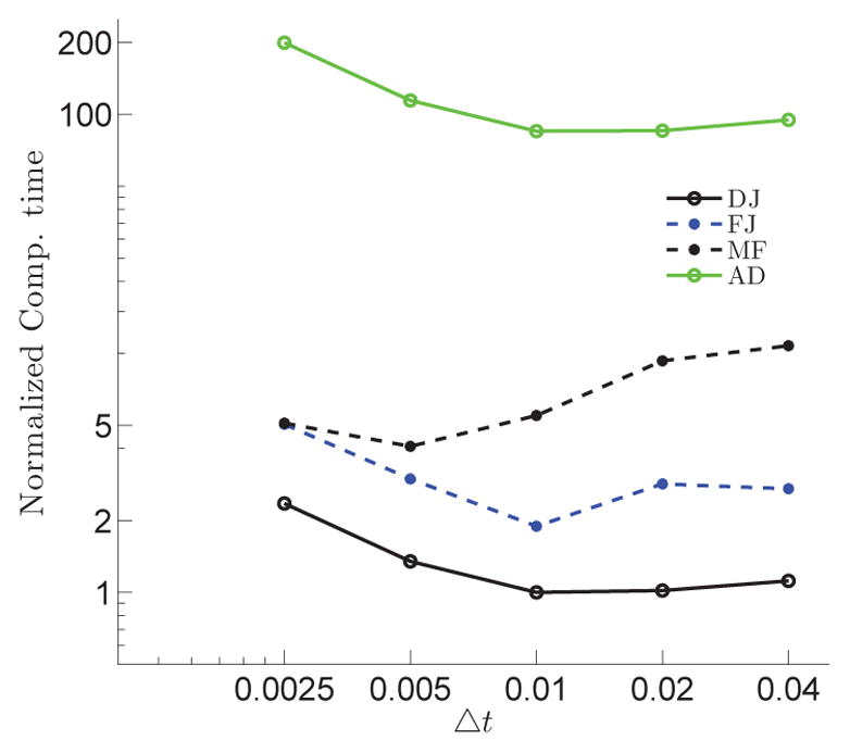
Computational time as function of time-step from initial time instant until t = 1 for steady flow in the 90° bend for different grids. The computational time is normalized by the minimum computational time for each method.
Table A.4.
components of the analytical Jacobian for 3D Navier-Stokes equations, where J is the Jacobian of the geometric transformation.
| ξ1 | ξ2 | ξ3 |
|
||
|---|---|---|---|---|---|
|
|
j | k |
|
||
|
|
j − 1 | k |
|
||
|
|
j | k − 1 |
|
||
|
|
j | k |
|
||
|
|
j | k + 1 |
|
||
|
|
j + 1 | k |
|
||
|
|
j − 1 | k |
|
||
|
|
j | k − 1 |
|
||
|
|
j | k |
|
||
|
|
j | k + 1 |
|
||
|
|
j + 1 | k |
|
||
|
|
j − 1 | k |
|
||
|
|
j | k − 1 |
|
||
|
|
j | k |
|
||
|
|
j | k + 1 |
|
||
|
|
j + 1 | k |
|
||
|
|
j | k |
|
Table A.5.
components of the analytical Jacobian for 3D Navier-Stokes equations, where J is the Jacobian of the geometric transformation.
| ξ1 | ξ2 | ξ3 |
|
||
|---|---|---|---|---|---|
| i |
|
k |
|
||
| i + 1 |
|
k |
|
||
| i |
|
k |
|
||
| i + 1 |
|
k |
|
Table A.6.
components of the analytical Jacobian for 3D Navier-Stokes equations, where J is the Jacobian of the geometric transformation.
| ξ1 | ξ2 | ξ3 |
|
||
|---|---|---|---|---|---|
| i | j |
|
|
||
| i + 1 | j |
|
|
||
| i | j |
|
|
||
| i + 1 | j |
|
|
Table A.7.
components of the analytical Jacobian for 3D Navier-Stokes equations, where J is the Jacobian of the geometric transformation.
| ξ1 | ξ2 | ξ3 |
|
||
|---|---|---|---|---|---|
|
|
j | k |
|
||
|
|
j + 1 | k |
|
||
|
|
j | k |
|
||
|
|
j + 1 | k |
|
Table A.8.
components of the analytical Jacobian for 3D Navier-Stokes equations, where J is the Jacobian of the geometric transformation.
| ξ1 | ξ2 | ξ3 |
|
||
|---|---|---|---|---|---|
| i |
|
k |
|
||
| i − 1 |
|
k |
|
||
| i |
|
k − 1 |
|
||
| i |
|
k |
|
||
| i |
|
k + 1 |
|
||
| i + 1 |
|
k |
|
||
| i − 1 |
|
k |
|
||
| i |
|
k − 1 |
|
||
| i |
|
k |
|
||
| i |
|
k + 1 |
|
||
| i + 1 |
|
k |
|
||
| i − 1 |
|
k |
|
||
| i |
|
k − 1 |
|
||
| i |
|
k |
|
||
| i |
|
k + 1 |
|
||
| i + 1 |
|
k |
|
||
| i |
|
k |
|
Table A.9.
components of the analytical Jacobian for 3D Navier-Stokes equations, where J is the Jacobian of the geometric transformation.
| ξ1 | ξ2 | ξ3 |
|
||
|---|---|---|---|---|---|
| i | j |
|
|
||
| i | j + 1 |
|
|
||
| i | j |
|
|
||
| i | j + 1 |
|
|
Table A.10.
components of the analytical Jacobian for 3D Navier-Stokes equations, where J is the Jacobian of the geometric transformation.
| ξ1 | ξ2 | ξ3 |
|
||
|---|---|---|---|---|---|
|
|
j | k |
|
||
|
|
j | k + 1 |
|
||
|
|
j | k |
|
||
|
|
j | k + 1 |
|
Table A.11.
components of the analytical Jacobian for 3D Navier-Stokes equations, where J is the Jacobian of the geometric transformation.
| ξ1 | ξ2 | ξ3 |
|
||
|---|---|---|---|---|---|
| i |
|
k |
|
||
| i |
|
k + 1 |
|
||
| i |
|
k |
|
||
| i |
|
k + 1 |
|
Table A.12.
components of the analytical Jacobian for 3D Navier-Stokes equations, where J is the Jacobian of the geometric transformation.
| ξ1 | ξ2 | ξ3 |
|
||
|---|---|---|---|---|---|
| i | j |
|
|
||
| i | j − 1 |
|
|
||
| i − 1 | j |
|
|
||
| i | j |
|
|
||
| i + 1 | j |
|
|
||
| i | j + 1 |
|
|
||
| i | j − 1 |
|
|
||
| i − 1 | j |
|
|
||
| i | j |
|
|
||
| i + 1 | j |
|
|
||
| i | j + 1 |
|
|
||
| i | j − 1 |
|
|
||
| i − 1 | j |
|
|
||
| i | j |
|
|
||
| i + 1 | j |
|
|
||
| i | j + 1 |
|
|
||
| i | j |
|
|
Footnotes
Publisher's Disclaimer: This is a PDF file of an unedited manuscript that has been accepted for publication. As a service to our customers we are providing this early version of the manuscript. The manuscript will undergo copyediting, typesetting, and review of the resulting proof before it is published in its final citable form. Please note that during the production process errors may be discovered which could affect the content, and all legal disclaimers that apply to the journal pertain.
References
- 1.Peskin C. Numerical Analysis of Blood Flow in the Heart. Journal of Computational Physics. 1977;25:220. [Google Scholar]
- 2.Peskin C, McQueen D. A three-dimensional computational method for blood flow in the heart. 1. Immersed elastic fibers in a viscous incompressible fluid. Journal of Computational Physics. 1989;81(2):372–405. [Google Scholar]
- 3.Steinman DA, Milner JS, Norley CJ, Lownie SP, Holdsworth DW. Image-based computational simulation of flow dynamics in a giant intracranial aneurysm. American Journal of Neuroradiology. 2003;24(4):559–566. [PMC free article] [PubMed] [Google Scholar]
- 4.Castro MA, Olivares MCA, Putman CM, Cebral JR. Unsteady wall shear stress analysis from image-based computational fluid dynamic aneurysm models under newtonian and casson rheological models. Medical & biological engineering & computing. 2014;52(10):827–839. doi: 10.1007/s11517-014-1189-z. [DOI] [PubMed] [Google Scholar]
- 5.Chiastra C, Morlacchi S, Gallo D, Morbiducci U, Cárdenes R, Larrabide I, Migliavacca F. Computational fluid dynamic simulations of image-based stented coronary bifurcation models. Journal of The Royal Society Interface. 2013;10(84):20130193. doi: 10.1098/rsif.2013.0193. [DOI] [PMC free article] [PubMed] [Google Scholar]
- 6.Borazjani I. Fluid-structure interaction, immersed boundary-finite element method simulations of bio-prosthetic heart valves. Computer Methods in Applied Mechanics and Engineering. 2013;257(0):103–116. [Google Scholar]
- 7.Borazjani I, Westerdale J, McMahon E, Rajaraman PK, Heys J, Belohlavek M. Left ventricular flow analysis: Recent advances in numerical methods and applications in cardiac ultrasound., Computational and Mathematical Methods in Medicine. Special Issue: Computational Analysis of Coronary and Ventricular Hemodynamics. 2013;2013:395081–11. doi: 10.1155/2013/395081. [DOI] [PMC free article] [PubMed] [Google Scholar]
- 8.Aono H, Liang F, Liu H. Near-and far-field aerodynamics in insect hovering flight: an integrated computational study. Journal of Experimental Biology. 2008;211(2):239–257. doi: 10.1242/jeb.008649. [DOI] [PubMed] [Google Scholar]
- 9.Nakata T, Liu H. A fluid–structure interaction model of insect flight with flexible wings. Journal of Computational Physics. 2012;231(4):1822–1847. [Google Scholar]
- 10.Borazjani I, Sotiropoulos F, Malkiel E, Katz J. On the role of copepod antenna in the production of hydrodynamic force during hopping. Journal of Experimental Biology. 2010;213:3019–3035. doi: 10.1242/jeb.043588. [DOI] [PubMed] [Google Scholar]
- 11.Borazjani I. The functional role of caudal and anal/dorsal fins during the c-start of a bluegill sunfish. The Journal of Experimental Biology. 2013;216:1658–1669. doi: 10.1242/jeb.079434. [DOI] [PubMed] [Google Scholar]
- 12.Borazjani I, Daghooghi M. The fish tail motion forms an attached leading edge vortex. Proceedings of the Royal Society B. 2013;280:20122071. doi: 10.1098/rspb.2012.2071. [DOI] [PMC free article] [PubMed] [Google Scholar]
- 13.Dong H, Bozkurttas M, Mittal R, Madden P, Lauder G. Computational modelling and analysis of the hydrodynamics of a highly deformable fish pectoral fin. Journal of Fluid Mechanics. 2010;645(-1):345–373. [Google Scholar]
- 14.Fogelson AL, Peskin CS. A fast numerical method for solving the three-dimensional stokes’ equations in the presence of suspended particles. Journal of Computational Physics. 1988;79(1):50–69. [Google Scholar]
- 15.Haddadi H, Morris JF. Microstructure and rheology of finite inertia neutrally buoyant suspensions. Journal of Fluid Mechanics. 2014;749:431–459. [Google Scholar]
- 16.Wu J, Aidun CK. A method for direct simulation of flexible fiber suspensions using lattice boltzmann equation with external boundary force. International Journal of Multiphase Flow. 2010;36(3):202–209. [Google Scholar]
- 17.Griffith BE. Immersed boundary model of aortic heart valve dynamics with physiological driving and loading conditions. International Journal for Numerical Methods in Biomedical Engineering. 2012;28(3):317–345. doi: 10.1002/cnm.1445. [DOI] [PubMed] [Google Scholar]
- 18.Mittal R, Dong H, Bozkurttas M, Najjar F, Vargas A, Von Loebbecke A. A versatile sharp interface immersed boundary method for incompressible flows with complex boundaries. Journal of computational physics. 2008;227(10):4825–4852. doi: 10.1016/j.jcp.2008.01.028. [DOI] [PMC free article] [PubMed] [Google Scholar]
- 19.Mangual JO, Kraigher-Krainer E, De Luca A, Toncelli L, Shah A, Solomon S, Galanti G, Domenichini F, Pedrizzetti G. Comparative numerical study on left ventricular fluid dynamics after dilated cardiomyopathy. Journal of biomechanics. 2013;46(10):1611–1617. doi: 10.1016/j.jbiomech.2013.04.012. [DOI] [PubMed] [Google Scholar]
- 20.Domenichini F, Pedrizzetti G. Intraventricular vortex flow changes in the infarcted left ventricle: numerical results in an idealised 3d shape. Computer Methods in Biomechanics and Biomedical Engineering. 2011;14(01):95–101. doi: 10.1080/10255842.2010.485987. [DOI] [PubMed] [Google Scholar]
- 21.De Tullio M, Cristallo A, Balaras E, Verzicco R. Direct numerical simulation of the pulsatile flow through an aortic bileaflet mechanical heart valve. Journal of Fluid Mechanics. 2009;622:259–290. [Google Scholar]
- 22.Tytell ED, Hsu CY, Williams TL, Cohen AH, Fauci LJ. Interactions between internal forces, body stiffness, and fluid environment in a neuromechanical model of lamprey swimming. Proceedings of the National Academy of Sciences. 2010;107(46):19832–19837. doi: 10.1073/pnas.1011564107. [DOI] [PMC free article] [PubMed] [Google Scholar]
- 23.Knoll DA, Keyes DE. Jacobian-free newton–krylov methods: a survey of approaches and applications. Journal of Computational Physics. 2004;193(2):357–397. [Google Scholar]
- 24.Anderson DG. Iterative procedures for nonlinear integral equations. Journal of the ACM (JACM) 1965;12(4):547–560. [Google Scholar]
- 25.Breuer M, Hänel D. A dual time-stepping method for 3-d, viscous, incompressible vortex flows. Computers & fluids. 1993;22(4):467–484. [Google Scholar]
- 26.Kim WW, Menon S. An unsteady incompressible navier–stokes solver for large eddy simulation of turbulent flows. International Journal for Numerical Methods in Fluids. 1999;31(6):983–1017. [Google Scholar]
- 27.Van Doormaal J, Raithby G. Enhancements of the simple method for predicting incompressible fluid flows. Numerical heat transfer. 1984;7(2):147–163. [Google Scholar]
- 28.Kim SW, Benson T. Comparison of the smac, piso and iterative time-advancing schemes for unsteady flows. Computers & fluids. 1992;21(3):435–454. [Google Scholar]
- 29.Tang H, Sotiropoulos F. Fractional step artificial compressibility schemes for the unsteady incompressible navier–stokes equations. Computers & fluids. 2007;36(5):974–986. [Google Scholar]
- 30.Pletcher RH, Tannehill JC, Anderson D. Computational fluid mechanics and heat transfer. CRC Press; 2012. [Google Scholar]
- 31.Brown PN, Saad Y. Hybrid krylov methods for nonlinear systems of equations. SIAM Journal on Scientific and Statistical Computing. 1990;11(3):450–481. [Google Scholar]
- 32.Dembo RS, Eisenstat SC, Steihaug T. Inexact newton methods. SIAM Journal on Numerical analysis. 1982;19(2):400–408. [Google Scholar]
- 33.Chan TF, Jackson KR. Nonlinearly preconditioned krylov subspace methods for discrete newton algorithms. SIAM Journal on scientific and statistical computing. 1984;5(3):533–542. [Google Scholar]
- 34.Knoll D, Mousseau V. On newton–krylov multigrid methods for the incompressible navier–stokes equations. Journal of Computational Physics. 2000;163(1):262–267. [Google Scholar]
- 35.Knoll D, Rider W. A multigrid preconditioned newton–krylov method. SIAM Journal on Scientific Computing. 1999;21(2):691–710. [Google Scholar]
- 36.Pernice M, Tocci M. A multigrid-preconditioned newton–krylov method for the incompressible navier–stokes equations. SIAM Journal on Scientific Computing. 2001;23(2):398–418. [Google Scholar]
- 37.Ge L, Sotiropoulos F. A numerical method for solving the 3d unsteady incompressible navier–stokes equations in curvilinear domains with complex immersed boundaries. Journal of computational physics. 2007;225(2):1782–1809. doi: 10.1016/j.jcp.2007.02.017. [DOI] [PMC free article] [PubMed] [Google Scholar]
- 38.Keyes DE, Reynolds DR, Woodward CS. Journal of Physics: Conference Series. Vol. 46. IOP Publishing; 2006. Implicit solvers for large-scale nonlinear problems; p. 433. [Google Scholar]
- 39.Eisenstat SC, Walker HF. Globally convergent inexact newton methods. SIAM Journal on Optimization. 1994;4(2):393–422. [Google Scholar]
- 40.Dembo RS, Eisenstat SC, Steihaug T. Inexact newton methods. SIAM Journal on Numerical analysis. 1982;19(2):400–408. [Google Scholar]
- 41.Losch M, Fuchs A, Lemieux JF, Vanselow A. A parallel jacobian-free newton–krylov solver for a coupled sea ice-ocean model. Journal of Computational Physics. 2014;257:901–911. [Google Scholar]
- 42.Chen R, Wu Y, Yan Z, Zhao Y, Cai XC. A parallel domain decomposition method for 3d unsteady incompressible flows at high reynolds number. Journal of Scientific Computing. 2014;58(2):275–289. [Google Scholar]
- 43.Outtier P, Cinnella P. Coupled/uncoupled solutions of rans equations using a jacobian-free newton-krylov method [Google Scholar]
- 44.Birken P, Gassner G, Haas M, Munz CD. Preconditioning for modal discontinuous galerkin methods for unsteady 3d navier–stokes equations. Journal of Computational Physics. 2013;240:20–35. [Google Scholar]
- 45.Walker HF. Implementation of the gmres method using householder transformations. SIAM Journal on Scientific and Statistical Computing. 1988;9(1):152–163. [Google Scholar]
- 46.Saad Y. A flexible inner-outer preconditioned gmres algorithm. SIAM Journal on Scientific Computing. 1993;14(2):461–469. [Google Scholar]
- 47.Hestenes MR, Stiefel E. Methods of conjugate gradients for solving linear systems. Vol. 49. National Bureau of Standards; Washington, DC: 1952. [Google Scholar]
- 48.Reid JK. On the Method of Conjugate Gradients for the Solution of Large Sparse Systems of Linear Equations. In: Reid JK, editor. Large Sparse Sets of Linear Equations. Academic Press; New York: 1971. [Google Scholar]
- 49.Hovland PD, McInnes LC. Parallel simulation of compressible flow using automatic differentiation and petsc. Parallel Computing. 2001;27(4):503–519. [Google Scholar]
- 50.Hovland P, Mohammadi B, Bischof C. Computational Methods for Optimal Design and Control. Springer; 1998. Automatic differentiation and navier-stokes computations; pp. 265–284. [Google Scholar]
- 51.Bramkamp F, Bücker H, Rasch A. Using exact jacobians in an implicit newton–krylov method. Computers & fluids. 2006;35(10):1063–1073. [Google Scholar]
- 52.Forth SA, Tadjouddine M, Pryce JD, Reid JK. Jacobian code generated by source transformation and vertex elimination can be as efficient as hand-coding. ACM Transactions on Mathematical Software (TOMS) 2004;30(3):266–299. [Google Scholar]
- 53.Briley W, McDonald H. Solution of the three-dimensional compressible navier-stokes equations by an implicit technique. Proceedings of the Fourth International Conference on Numerical Methods in Fluid Dynamics; Springer; 1975. pp. 105–110. [Google Scholar]
- 54.Beam RM, Warming RF. An implicit finite-difference algorithm for hyperbolic systems in conservation-law form. Journal of Computational Physics. 1976;22(1):87–110. [Google Scholar]
- 55.Beam RM, Warming R. An implicit factored scheme for the compressible navier-stokes equations. AIAA journal. 1978;16(4):393–402. [Google Scholar]
- 56.Steger J. Implicit finite difference simulation of flow about arbitrary geometries with application to airfoils [Google Scholar]
- 57.Pulliam TH, Steger JL. Implicit finite-difference simulations of three-dimensional compressible flow. AIAA Journal. 1980;18(2):159–167. [Google Scholar]
- 58.Pulliam TH, Chaussee D. A diagonal form of an implicit approximate-factorization algorithm. Journal of Computational Physics. 1981;39(2):347–363. [Google Scholar]
- 59.Hoffmann KA, Chiang ST. Computational fluid dynamics. Vol. 1. Wichita, KS: Engineering Education System; [Google Scholar]
- 60.Batten P, Leschziner M, Goldberg U. Average-state jacobians and implicit methods for compressible viscous and turbulent flows. Journal of computational physics. 1997;137(1):38–78. [Google Scholar]
- 61.Barth T. Analysis of implicit local linearization techniques for tvd and upwind algorithms. 1987 [Google Scholar]
- 62.Gilmanov A, Sotiropoulos F. A hybrid cartesian/immersed boundary method for simulating flows with 3d, geometrically complex, moving bodies. Journal of Computational Physics. 2005;207(2):457–492. [Google Scholar]
- 63.Borazjani I, Ge L, Sotiropoulos F. Curvilinear immersed boundary method for simulating fluid structure interaction with complex 3d rigid bodies. Journal of Computational physics. 2008;227(16):7587–7620. doi: 10.1016/j.jcp.2008.04.028. [DOI] [PMC free article] [PubMed] [Google Scholar]
- 64.Borazjani I, Ge L, Le T, Sotiropoulos F. A parallel overset-curvilinear-immersed boundary framework for simulating complex 3d incompressible flows. Computers & fluids. 2013;77:76–96. doi: 10.1016/j.compfluid.2013.02.017. [DOI] [PMC free article] [PubMed] [Google Scholar]
- 65.Mousseau V, Knoll D, Reisner J. An implicit nonlinearly consistent method for the two-dimensional shallow-water equations with coriolis force. Monthly weather review. 2002;130(11):2611–2625. [Google Scholar]
- 66.Knoll D, McHugh P. Enhanced nonlinear iterative techniques applied to a nonequilibrium plasma flow. SIAM Journal on Scientific Computing. 1998;19(1):291–301. [Google Scholar]
- 67.Luo H, Baum JD, Löhner R. A fast, matrix-free implicit method for compressible flows on unstructured grids. Journal of Computational Physics. 1998;146(2):664–690. [Google Scholar]
- 68.Liu F, Ji S. Unsteady flow calculations with a multigrid navier-stokes method. AIAA journal. 1996;34(10):2047–2053. [Google Scholar]
- 69.Liu F, Cai J, Zhu Y, Tsai H, Wong AF. Calculation of wing flutter by a coupled fluid-structure method. Journal of Aircraft. 2001;38(2):334–342. [Google Scholar]
- 70.Yusuf MW, Leong JW, Abu Hassan M, Monsi M. A new newtons method with diagonal jacobian approximation for systems of nonlinear equations. Journal of Mathematics and Statistics. 2010;6(3):246–252. [Google Scholar]
- 71.Wright MJ, Candler GV, Prampolini M. Data-parallel lower-upper relaxation method for the navier-stokes equations. AIAA journal. 1996;34(7):1371–1377. [Google Scholar]
- 72.Radhakrishnan K, Hindmarsh AC. Description and use of LSODE, the Livermore solver for ordinary differential equations. National Aeronautics and Space Administration, Office of Management, Scientific and Technical Information Program. 1993 [Google Scholar]
- 73.Balay S, Abhyankar S, Adams MF, Brown J, Brune P, Buschelman K, Eijkhout V, Gropp WD, Kaushik D, Knepley MG, McInnes LC, Rupp K, Smith BF, Zhang H. PETSc Web page. 2014 http://www.mcs.anl.gov/petsc. http://www.mcs.anl.gov/petsc.
- 74.Axelsson O. Iterative solution methods. Cambridge University Press; 1996. [Google Scholar]
- 75.Borazjani I, Sotiropoulos F. Numerical investigation of the hydrodynamics of carangiform swimming in the transitional and inertial flow regimes. Journal of Experimental Biology. 2008;211(10):1541–1558. doi: 10.1242/jeb.015644. [DOI] [PubMed] [Google Scholar]
- 76.Chorin AJ. Numerical solution of the navier-stokes equations. Mathematics of computation. 1968;22(104):745–762. [Google Scholar]
- 77.Kim J, Moin P. Application of a fractional-step method to incompressible navier-stokes equations. Journal of computational physics. 1985;59(2):308–323. [Google Scholar]
- 78.Dütsch H, Durst F, Becker S, Lienhart H. Low-reynolds-number flow around an oscillating circular cylinder at low keulegan–carpenter numbers. Journal of Fluid Mechanics. 1998;360:249–271. [Google Scholar]
- 79.Rindt C, Van Steenhoven A, Janssen J, Vossers G. Unsteady entrance flow in a 90 curved tube. Journal of Fluid Mechanics. 1991;226:445–474. [Google Scholar]
- 80.Bovendeerd P, Van Steenhoven A, Van de Vosse F, Vossers G. Steady entry flow in a curved pipe. Journal of Fluid Mechanics. 1987;177:233–246. [Google Scholar]
- 81.Saad Y. Numerical methods for large eigenvalue problems. Vol. 158. SIAM; 1992. [Google Scholar]
- 82.You D, Mittal R, Wang M, Moin P. Analysis of stability and accuracy of finite-difference schemes on a skewed mesh. Journal of Computational Physics. 2006;213(1):184–204. [Google Scholar]
- 83.Higham NJ. Accuracy and stability of numerical algorithms. Siam; 2002. [Google Scholar]
- 84.Busquets-Mataix JV, Serrano JJ, Ors R, Gil P, Wellings A. Adding instruction cache effect to schedulability analysis of preemptive real-time systems, in: Real-Time Technology and Applications Symposium, 1996. Proceedings., 1996 IEEE, IEEE; 1996; pp. 204–212. [Google Scholar]
- 85.Xiang J, Natarajan SK, Tremmel M, Ma D, Mocco J, Hopkins LN, Siddiqui AH, Levy EI, Meng H. Hemodynamic–morphologic discriminants for intracranial aneurysm rupture. Stroke. 2011;42(1):144–152. doi: 10.1161/STROKEAHA.110.592923. [DOI] [PMC free article] [PubMed] [Google Scholar]
- 86.Oka S, Nakai M. Optimality principle in vascular bifurcation. Biorheology. 1986;24(6):737–751. doi: 10.3233/bir-1987-24624. [DOI] [PubMed] [Google Scholar]
- 87.Xiang J, Siddiqui A, Meng H. The effect of inlet waveforms on computational hemodynamics of patient-specific intracranial aneurysms. Journal of biomechanics. doi: 10.1016/j.jbiomech.2014.09.034. [DOI] [PMC free article] [PubMed] [Google Scholar]
- 88.Torii R, Oshima M, Kobayashi T, Takagi K, Tezduyar TE. Fluid–structure interaction modeling of aneurysmal conditions with high and normal blood pressures. Computational Mechanics. 2006;38(4–5):482–490. [Google Scholar]
- 89.Ekici K, Lyrintzis AS. Short communication: A parallel newton–krylov method for navier–stokes rotorcraft codes. International Journal of Computational Fluid Dynamics. 2003;17(3):225–230. [Google Scholar]


