Fig. 4.
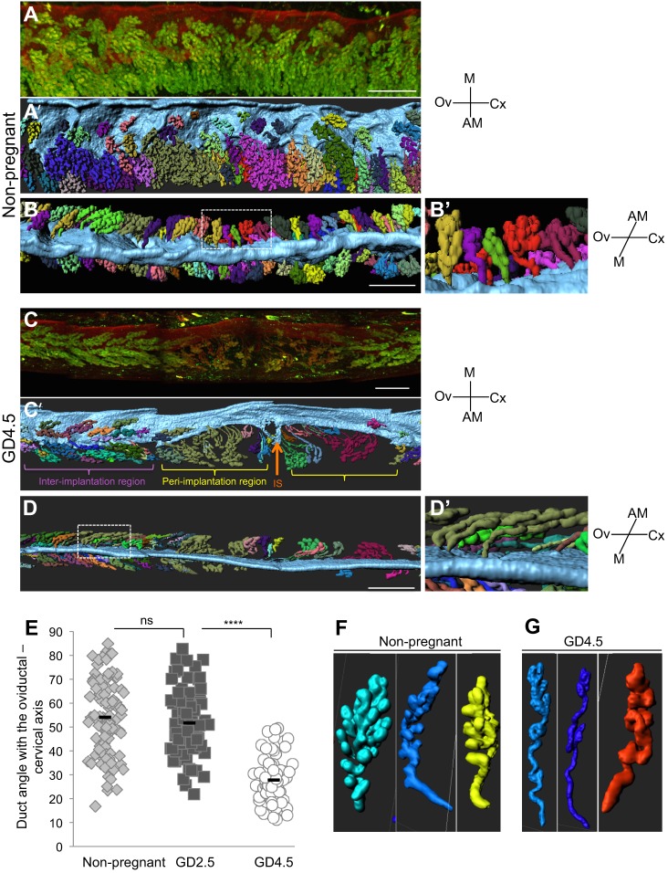
Glandular ducts reorient towards the site of implantation. (A-D′) 3D images and surface renderings of luminal segments and uterine glands, with separate glandular structures randomly pseudocolored for easy visualization. (A-B′) View from the ventral side (A,A′) and mesometrial side (B,B′) of non-pregnant uterine segment. (C-D′) View from the ventral side (C,C′) and mesometrial side (D,D′) of GD4.5 uterine segment. Boxed areas in B,D represent magnified regions in B′,D′, respectively. (E) The glandular ducts in non-pregnant uteri (B,B′) are at a mean angle of ∼54° to the uterine oviductal-cervical axis. (D,D′) With the introduction of the embryo (orange arrow) at the anti-mesometrial pole at GD4.5, the glandular ducts bend drastically until they are at a mean angle of ∼28° to the oviductal-cervical axis towards the site of implantation. The duct angle was measured in a total of 70-80 ducts from two different mice and around three embryos at GD4.5 (E). A t-test was used for statistical analysis and significance was defined as P<0.001. ****P<10−12; ns, not significant. (F,G) Representative examples of glandular branching in non-pregnant uteri (F), and glandular branching, coiling and duct elongation in GD4.5 uteri (G). Scale bars: 500 μm in A-D′. M, mesometrial; AM, anti-mesometrial; Ov, ovary; Cx, cervix; IS, implantation site.

