Abstract
Electrospinning has been widely used to fabricate scaffolds imitating the structure of natural extracellular matrix (ECM). However, conventional electrospinning produces tightly compacted nanofiber layers with only small superficial pores and a lack of bioactivity, which limit the usefulness of electrospinning in biomedical applications. Thus, a porous poly(ε-caprolactone) (PCL)/gelatin composite electrospun scaffold with crater-like structures was developed. Porous crater-like structures were created on the scaffold by a gas foaming/salt leaching process; this unique fiber structure had more large pore areas and higher porosity than the conventional electrospun fiber network. Various ratios of PCL/gelatin (concentration ratios: 100/0, 75/25, and 50/50) composite electrospun scaffolds with and without crater-like structures were characterized by their microstructures, surface chemistry, degradation, mechanical properties, and ability to facilitate cell growth and infiltration. The combination of PCL and gelatin endowed the scaffold with both structural stability of PCL and bioactivity of gelatin. All ratios of scaffolds with crater-like structures showed fairly similar surface chemistry, degradation rates, and mechanical properties to equivalent scaffolds without crater-like structures; however, craterized scaffolds displayed higher human mesenchymal stem cell (hMSC) proliferation and infiltration throughout the scaffolds after 7-day culture. Therefore, these results demonstrated that PCL/gelatin composite electrospun scaffolds with crater-like structures can provide a structurally and biochemically improved three-dimensional ECM-mimicking microenvironment.
Keywords: ECM mimic, crater-like structure, PCL/gelatin composite, electrospun
INTRODUCTION
The design goal of tissue engineering scaffolds is to facilitate the regeneration of damaged tissue by providing a cell nurturing microenvironment. Tissues and organs consist of various cell types and extracellular matrix (ECM) which provides a protective, nurturing microenvironment for cells. The ECM is a complex network of proteoglycans and fibrous proteins with both structural and regulatory roles.1 The ECM interacts with cells via specific ligands for cell adhesion and migration, and also regulates cell proliferation and differentiation.2,3 Thus, the design of a tissue scaffold which incorporates fundamental roles of ECM enables the construction of highly organized structures, which provide cell adhesive regions, mechanical stability, and structural guidance.4 This allows the scaffold to have active interfaces which respond to biological and physiological signals and also remodel the ECM microenvironment for integration into the surrounding host tissue.5 In this study, we describe the development of an ECM-mimicking scaffold using a porous electrospun poly(ε-caprolactone) (PCL) and gelatin nanofibrous composite with crater-like structures.
Electrospinning is a fabrication technique that uses an electrical field to generate continuous solid fibers of materials with diameters on the nano- or micrometer scale. This technique has obtained a lot of attention in tissue engineering fields because of its ease of producing fibrous scaffolds, cost effectiveness, and tunability by simply modifying the parameters of the electrospinning process, such as polymer concentration and applied voltage.6 Notably, electrospinning is capable of producing a scaffold with highly interconnected, nonwoven nanofibers which are very similar to the fibrillar structure of ECM.7 This ECM-mimicking feature allows the electrospun scaffold to support the attachment, proliferation, and function of various cell types such as bone, cartilage, skin, and neurons.8–11 However, one of the major challenges in the tissue engineering application of the conventional electrospun scaffold is that it has tightly packed layers of nanofibers with a merely superficial porous network; the results are limited to a simple two-dimensional (2D) surface scaffold, which does not allow cell penetration and growth through the scaffold.12,13 This compressed, 2D scaffold limits intricate cell–cell and cell–ECM interactions and subsequent cell signaling necessary in an in vivo three-dimensional (3D) environment,14 thereby reducing engraftment of the implanted cells.
Several approaches to overcoming the limited porosity of electrospun scaffolds have been explored. One approach is the salt-leaching method, which involves incorporating salts into the polymer fibers during electrospinning and then dissolving them after the scaffold has formed.15 This method stimulated cell migration into the scaffold through the salt generated pores, but showed only marginal and localized cellular infiltration. This may be attributed to the fact that the simple salt leaching approach only creates disconnected pores in the fiber structure. Another approach is electrospraying hydrogels into the scaffold as it forms.16 However, during the electrospraying process, it is difficult to control the hydrogel dispersion into the scaffold, which leads to a non-uniform construct. Wet electrospinning is also another approach to enhance porosity of the electrospun scaffold. Electrospun nanofibers are collected on a liquid reservoir collector. The liquid, such as ethanol and methanol, induces dispersion of the depositing nanofibers and decreases the bulk density of the nanofiber structure, which creates a 3D sponge-like electrospun scaffold. However, this method still has some major challenges including the difficulties in selecting proper solvents and drying the scaffolds with the desired size of pores.17
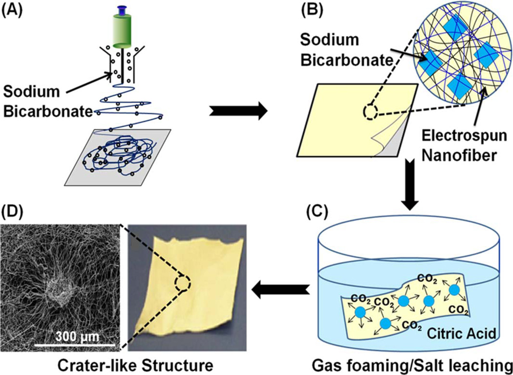
To overcome the limitations of these methods, in our study we combined a gas foaming and salt leaching strategy to generate pore spaces.18 During electrospinning, sodium bicarbonate particles were incorporated into the scaffold as the fibers deposited onto the collector. After the scaffold had formed, it was placed into a mildly acidic solution (citric acid). The citric acid reacted with the sodium bicarbonate to generate carbon dioxide (CO2) gas; this blowing gas expanded the scaffold to create crater-like structures. The crater-like structure has a loosely packed fiber network and its large pore areas are suitable for cell infiltration through the scaffold. These unique structures imitate the 3D aspect of an ECM structure, which allows more cell–cell and cell– ECM interactions through the scaffold than the conventional 2D electrospun fiber network.
Recently, various biodegradable synthetic polymers and natural biopolymers have been used to produce nanofiber scaffolds through electrospinning.6 Synthetic polyesters, such as PCL, poly(lactic acid) (PLA), and poly(lactic-co-glycolic acid) (PLGA), generally have good processability, chemical stability, and mechanical performance.19–22 In addition, these polymers are able to mimic the physical features and dimensions of the collagen in the native ECM. However, they show low hydrophilicity and a lack of cell recognition sites, which reduce cell–scaffold interactions. To enhance the bioactive functions of the scaffold, natural biopolymers, such as gelatin, collagen, and laminin, can be blended with the synthetic polymers.23–26 Natural biopolymers show excellent biocompatibility; however, their processability is poor and they generally have inadequate mechanical stability due to the chemical modification of polymer chain conformation and fast degradation.23 Thus, blending synthetic and natural polymers improves cell–scaffold interactions and control over the mechanical stability and degradation rate of the scaffold. By modifying the blended ratio for specific applications, this strategy can be a promising solution to compensate for the limitations of each polymer. In our study, PCL and gelatin were blended to produce a PCL/gelatin composite electrospun scaffold. PCL has been used in various biomedical applications, such as drug delivery devices, sutures, and implantable barriers.27,28 PCL has also been approved by the FDA and shows no toxic effects from degradation products.28,29 Gelatin, a derivative of collagen hydrolysis, is also widely used due to its biological properties, biodegradability, biocompatibility, and commercial feasibility at low cost.30,31 Therefore, by mixing PCL and gelatin, we can obtain a bioactive electrospun scaffold with mechanical stability which also biochemically and structurally mimics the native ECM.
In this study, we demonstrated the feasibility of developing a porous, ECM-mimicking, PCL/gelatin composite electrospun scaffold with crater-like structures. It is hypothesized that porous crater-like structures and PCL/gelatin composite nanofiber networks create a 3D, ECM-mimicking microenvironment, which can greatly improve the efficacy of cell scaffolds for tissue regeneration. We characterized the crater-like structures and confirmed cell infiltration through the scaffold. In addition, we tested scaffolds made from different ratios of PCL/gelatin by evaluating their chemical, mechanical, and biological properties. The analysis of these properties can be used to optimize the scaffolds for various tissue engineering applications.
METHODS
Fabrication of composite electrospun scaffolds with crater-like structures
PCL pellets (Mw = 65,000) and type A porcine-derived gelatin were purchased from Sigma Aldrich (St. Louis, MO). PCL and gelatin were mixed in 100/0, 75/25, 50/50, and 25/75 weight ratios. The mixtures were dissolved in 2,2,2-trifluor-oethanol (TFE) to obtain an 8.5 wt % solution. The solutions were collected into 10 mL syringes and capped with 25 gauge needle tips. The syringes were loaded into a syringe pump (KD Scientific, MA) at a constant flow rate of 1.0 mL/hour. A high-voltage supplier (Gamma High-Voltage Research, FL) was used to apply + 21 kV to the syringe needles and an electrically grounded, 8 cm × 8 cm aluminum sheet was used as the collecting surface. Under these conditions, solutions were electrospun for 2 hours.
For the gas foaming/salt leaching process (Fig. 1), sodium bicarbonate particles, previously sieved to sizes between 100 and 200 µm, were provided through the sheath surrounding the syringe.15 To optimize the frequency of crater-like structure formation on the surface of the scaffolds, electrospinning was conducted with different amounts of sodium bicarbonate added to the nanofibers (polymer to sodium bicarbonate weight ratios of 1:2, 1:6, 1:8, and 1:12). Sodium bicarbonate particles were interspersed into the scaffold for 45 seconds, at 5 minute intervals. After 2 hours, the scaffolds were placed into a 50% citric acid solution for 30 minutes. The scaffolds were washed three times in deionized (DI) water to remove any remaining salts, and then dried at room temperature.
FIGURE 1.
Creation of crater-like structures using gas foaming/salt leaching process. (A) Sodium bicarbonate incorporation into the electrospun nanofibers. (B) Sodium bicarbonate deposited between the electrospun nanofiber network. (C) Gas foaming/salt leaching process: generation of CO2 bubbles within the electrospun scaffold by the reaction of sodium bicarbonate and citric acid. (D) Crater-like structure produced after gas foaming/salt leaching process.
Morphology of composite electrospun scaffolds
Morphology of the composite electrospun nanofibers and crater-like structures was characterized by scanning electron microscope (SEM) imaging. PCL/gelatin composite electrospun scaffolds with and without crater-like structures were mounted onto an aluminum stump and sputter coated with gold and palladium. The scaffolds were imaged using a QuantaTM 650 FEG (FEI Co.) with an accelerating voltage of 10 kV. Fiber diameters were measured using Image J software (National Institute of Health, The United States). In addition, the pore areas within the crater-like structure were also measured using Image J software by the analysis of SEM images (750× magnification) of the scaffolds. The SEM images were optimized to threshold the proper fiber layer, and the pore areas were visualized and measured as a polygonal shape surrounded by the deposited electrospun nanofibers. The porosity of the crater-like structure was calculated from the total pore area divided by the total analyzed area (total pore area/total analyzed area). In addition, the frequency of crater-like structure formation on the scaffold was assessed by the number of crater-like structures per unit area of the scaffolds (number of craters/mm2); the data was obtained from the SEM images of the scaffolds.
Surface chemistry of composite electrospun scaffolds
Fourier transform infrared spectroscopy (FTIR, Nicolet Thermo Scientific Co.) was used to characterize the chemical structure of the PCL/gelatin composite electrospun scaffolds with and without crater-like structures. Spectra were collected from 4000 to 400 cm−1 at ambient temperature with 32 scans per sample in attenuated total refection (ATR) mode. Each scaffold was soaked in 1× phosphate buffered saline (PBS) at 37°C for 4 weeks. During this time period, FTIR was measured after 2 hours, 7 days, 14 days, and 28 days. Each patch was dried in a vacuum oven at room temperature for 2 day and then FTIR was measured to analyze the change in chemical structure at each time point.
Degradation of composite electrospun scaffolds
PCL/gelatin composite electrospun scaffolds with and without crater-like structures were weighed to determine the initial weight of each scaffold. The degradation condition was the same as the FTIR study; each scaffold was soaked in 1× PBS at 37°C for 4 weeks. During this time period, the weight of each scaffold was measured initially, after the first day, and after every third day (4 days, 7 days, 10 days, and so forth). Each patch was dried in a vacuum oven at room temperature for 2 days and then weighed to determine the change in mass at each time point.
Mechanical properties of composite electrospun scaffolds
In order to analyze the mechanical stability of different ratios of PCL/gelatin composite electrospun scaffolds with and without crater-like structures, uniaxial tensile testing was carried out on scaffolds of each PCL/gelatin ratio. The scaffolds were cut into rectangular sections with dimensions of 2.4 × 0.35 cm2 (scaffold thickness: 210 ± 25 µm) and tested for mechanical loading at a ramp force of 0.1 N/min using a DMA 2980 Dynamic Mechanical Analyzer (TA Instruments). At least five samples were tested for each type of scaffold.
Cell culture condition
Human mesenchymal stem cells (hMSCs) were purchased from Lonza, Inc. (Lonza, Walkersville, MD), and cultured in Dulbecco’s Modified Eagle’s Medium (DMEM), supplemented with 10% fetal bovine serum (FBS), 1% Amphotericin B, 1% penicillin, and 1% streptomycin. Cells were grown to 70%–80% confluence at normal culture conditions (37°C, 95% humidity, 5% CO2) before being seeded onto scaffolds.
Cell proliferation on composite electrospun scaffolds
Composite electrospun scaffolds with and without craterlike structures were cut into disks with 0.5 cm diameters, briefly sterilized under UV light for 30 minutes, and then placed into 48-well plates. About 50,000 hMSCs were seeded on each scaffold with 400 µL of media and cultured at normal culture conditions until 7 days; media was changed every 48 hours. An MTS [3-(4,5-dimethylthiazol-2-yl)−5-(3-carboxymethoxyphenyl)−2-(4-sulfophenyl)-2H-tetrazolium] assay (CellTiter 96 solution, Promega Co.) was performed to measure cell proliferation onto the scaffolds at 4 hours, 1 day, and 7 days after hMSC seeding. At least seven samples were tested for each type of scaffold.
Cell viability on composite electrospun scaffolds
To qualitatively assess viability and cell spreading on composite electrospun scaffolds with and without crater-like structures, 50,000 hMSCs were seeded onto the scaffolds and cultured at normal culture conditions (the same conditions as the cell proliferation study). A Live/Dead Viability/ Cytotoxicity assay (Molecular Probes Inc., OR) was used to stain for viable cells 7 days after cell seeding. Images of cells were taken using a Nikon fluorescent microscope and NIS Elements imaging software.
Cell infiltration through composite electrospun scaffolds
In order to characterize cells’ ability to penetrate through crater-like structures, a cell infiltration test was performed in composite electrospun scaffolds with and without craterlike structures. For this test, we developed an insert system to ensure that cell infiltration only occurred from the top of the scaffolds. 50,000 hMSCs were carefully seeded on the scaffolds of the insert system with 1 mL of media. The cells were cultured at normal culture conditions for 7 days, with media changes every 48 hours. After 1 and 7 days of incubation, the scaffolds were fixed with 10% formalin and placed in a 20% sucrose solution. Then, the scaffolds were embedded in Histoprep embedding medium and snap frozen in liquid nitrogen for cryosection, as described previously.12 Frozen blocks were sliced into 40 µm-thick sections using a Microm HM 505E cryostat (Instrumedics, IL) and the sections were stained with Hematoxylin and Eosin (H&E) dyes. Images were taken with a Nikon TE 2000-S microscope. The depth of hMSC infiltration through the scaffold was measured using Image J software. At least four samples were tested for each type of scaffold.
Statistical analysis
All the values are expressed as mean ± standard deviation. One-way ANOVA analysis was used to check for significant differences, and Tukey multiple comparison test was used to determine significant differences between pairs. SPSS software was used to perform statistical analysis. The p < 0.05 was considered to be statistically significant.
RESULTS AND DISCUSSIONS
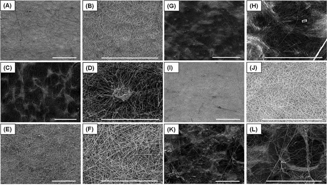
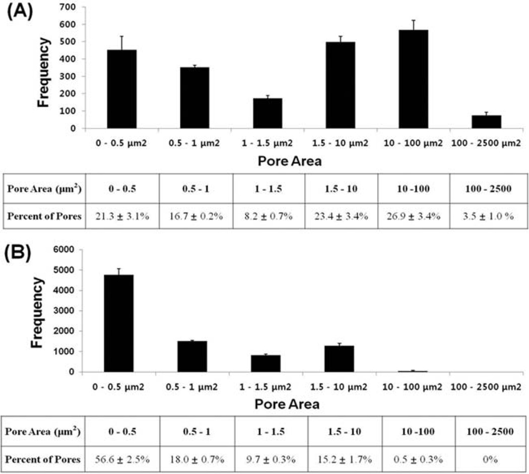
The composite electrospun scaffolds were successfully fabricated with three different ratios of PCL/gelatin concentration (100/0, 75/25, 50/50). The scaffolds without craterlike structures (PCL/gelatin ratio: 100/0, 75/25, 50/50) had uniform and bead-free fiber morphologies with average fiber diameters of 685 ± 263 nm, 705 ±155 nm, and 731 ± 150 nm, respectively; the nanofibers were arranged in a random, interwoven network as shown by SEM [Fig. 2(A–B, E–F, I–J)]. This interwoven network highly mimics natural ECM protein structure, such as a collagen fiber network.7,32 The SEM images presented that the scaffolds without crater-like structures had tightly packed nanofiber deposition which limits cell migration and proliferation within the scaffolds.12,33 Thus, to expand the porous spaces in the electrospun scaffold, crater-like structures were generated in the three scaffold concentration groups (PCL/gelatin ratio: 100/0, 75/25, 50/50) by the gas foaming/salt leaching process [Fig. 2(C–D, G–H, K–L)]. After electrospinning, the electrospun scaffold was placed into citric acid solution. Then, the sodium bicarbonate incorporated between nanofibers reacted with citric acid, which generated CO2 gas. This gas created bubbles under the deposited nanofibers. The bubbles suddenly stretched the nanofiber network and expanded the scaffold. When the gas dissipated, the expanded scaffold deflated, leaving a loosely packed nanofiber network where the sodium bicarbonate had been deposited. This loosely packed fiber network presented crater-like morphologies on the scaffold which were about 200–400 µm in diameter. The pore areas within this crater-like structure were measured using Image J software by analyzing the SEM images of the 100/0 PCL/gelatin scaffolds with crater-like structures [Fig. 2(D), 750× magnification]. The total number of pores within the crater-like structure was 2119 ± 189 and the distribution of pore areas is shown in Figure 3(A). About 26.9% of the total pores (568 ± 56) were between 10 and 100 µm2 in their areas. In addition, 3.5% of the total pores (74 ± 20) were even larger than 100 µm2. This range of pores (larger than 10 µm2) covered greater than 93% of total pore area within the crater-like structures. About 47% of the total pores (980 ± 94) were smaller than 1.5 µm2 and were mostly located at the center of the crater-like structure. As a control group, the pore areas of the conventional electrospun fiber network without crater-like structures were also measured by analyzing the SEM images of the 100/0 PCL/gelatin scaffolds without crater-like structures [Fig. 2(B), 750× magnification]. Total analyzed area was the same with the crater group, but the total pore numbers of the control group were higher (8420 ± 332) than the crater group (2119 ± 189) because the control group had many smaller pores. In the control group, about 56.6% of the total pores (4766 ± 308) were smaller than 0.5 µm2 and more than 99.5% of the total pores (8376 ± 293) were smaller than 10 µm2 [Fig. 3(B)]. The porosity of crater-like structure was also calculated from the total pore area divided by the total analyzed area. The area of crater-like structure showed 50.5% ± 4.6% porosity, but the area of control group had only 11.4% ± 2.2% porosity. In addition, the pore areas within the crater-like structure were also analyzed in 75/25 and 50/50 PCL/gelatin scaffolds with crater-like structures [Fig. 2(D,H)], and they showed very similar trends in the distribution of pore areas and the porosity to the 100/0 PCL/gelatin scaffolds with crater-like structures [Supplemented Fig. 1]. About 31.2% ± 3.3% and 27.4% ± 4.1% of total pores within the crater-like structure of 75/25 and 50/50 PCL/gelatin scaffolds were larger than 10 µm2, which covered greater than 91% and 95% of total pore areas in each crater; also, the porosity of each crater was 45.6% ± 4.2% and 52.2% ± 6.3%, respectively. Furthermore, as control groups, 75/25 and 50/50 PCL/gelatin scaffolds without crater-like structures [Fig. 2(F,J)] also presented similar trends in the pore area distribution and porosity (14% ± 3.6% and 10.6% ± 1.5% of porosity in each scaffold group) to the 100/0 PCL/gelatin scaffolds without craterlike structure. Therefore, this pore area analysis data demonstrates that the crater-like structures have larger pores and higher porosity than the conventional electrospun fiber network, which allows better cellular infiltration through the scaffold.
FIGURE 2.
SEM characterization of PCL/gelatin composite electrospun scaffolds with and without crater-like structures. (A) 100/0 PCL/gelatin scaffold without crater-like structures and (B) its magnified image. (C) 100/0 PCL/gelatin scaffold with crater-like structures and (D) its magnified image. (E) 75/25 PCL/gelatin scaffold without crater-like structures and (F) its magnified image. (G) 75/25 PCL/gelatin scaffold with crater-like structures and (H) its magnified image. (I) 50/50 PCL/gelatin scaffold without crater-like structures and (J) its magnified image. (K) 50/50 PCL/gelatin scaffold with crater-like structures and (L) its magnified image. (Scale bars = 300 µm).
FIGURE 3.
The distribution of pore areas within (A) a crater-like structure and (B) a conventional electrospun fibrous network of the 100/0 PCL/gelatin scaffolds. The number of pores and its percentage were counted based on the range of pore areas.
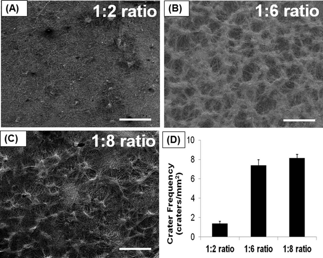
By changing the amount of sodium bicarbonate added to the nanofibers, we tried to optimize the frequency of craterlike structure formation on the electrospun scaffolds. As we increased the amount of sodium bicarbonate, more craterlike structures were generated on the electrospun scaffolds. The frequency of crater-like structure formation was assessed by the number of crater-like structures per unit surface area of the scaffolds. Only a few crater-like structures were produced at the 1:2 ratio (polymer to sodium bicarbonate weight ratio) on the 100/0 PCL/gelatin scaffold (crater frequency: 1.4 ± 0.22 craters/mm2) [Fig. 4(A)]. However, when the sodium bicarbonate amount was increased to a 1:6 ratio, most of the surface area of 100/0 PCL/gelatin scaffold was covered with crater-like structures (7.38 ± 0.5 craters/mm2) and each crater was connected with the others [Fig. 4(B)]. At the 1:8 ratio, the crater frequency (8.16 ± 0.37 craters/mm2) of 100/0 PCL/gelatin scaffold was slightly increased, the scaffold surface was saturated with craters, and the scaffold showed a highly connected porous crater network [Fig. 4(C)]. If the ratio increased to greater than 1:12, the 100/0 PCL/gelatin scaffold started to separate into multiple layers; thus, too much sodium bicarbonate deposition between the nanofibers might hinder proper fiber network formation and cause layer separation of electrospun scaffolds. 75/25 and 50/50 PCL/gelatin scaffolds also showed similar trends in crater formation as with 100/0 scaffolds (Not shown in Figure). Also, different PCL to sodium bicarbonate weight ratio (1:2, 1:6, and 1:8) did not significantly affect the scaffold stability and the property of fiber network of 100/0, 75/25, and 50/50 PCL/gelatin scaffolds.
FIGURE 4.
Optimization of crater frequency on the surface of electrospun scaffold by changing sodium bicarbonate amount added to electro-spun nanofibers. (A) Crater-like structure formation at 1:2 ratio (polymer to sodium bicarbonate weight ratio) and (B) at 1:6 ratio and (C) at 1:8 ratio on 100/0 PCL/gelatin scaffolds. (D) Crater frequency was assessed by the number of crater-like structures per unit surface area of the scaffold at each ratio. (Scale bar = 500 µm).
Thus, the gas foaming/salt leaching process with different PCL-to-sodium bicarbonate ratio (from 1:2 to 1:8) did not significantly affect the stability and network structure of the scaffolds, if at least greater than 50% of PCL is incorporated.
About 1:8 ratio was selected for this study since it displayed a highly connected porous crater network, was saturated with craters, and there was no layer separation.
The scaffolds with crater-like structures of 100/0 and 75/25 PCL/gelatin showed a distinct fibrous network [Fig. 2(C–D, G–H); average fiber diameter: 681 ± 136 nm and 737 ± 139 nm, respectively], while the 50/50 PCL/gelatin scaffold with crater-like structures exhibited a less clear, slightly dissolved network due to its higher gelatin content [Fig. 2(K–L); average fiber diameter: 854 ± 218 nm]. In addition, we tried to fabricate 25/75 PCL/gelatin scaffolds with crater-like structures, but the structures collapsed due to gelatin dissolution during the gas foaming/salt leaching process. Thus, the crater-like connected pores were successfully created on 100/0, 75/25, and 50/50 PCL/gelatin scaffolds, and these pores may allow better cell infiltration and serve as an exchange path for nutrients and metabolic waste throughout the scaffold.
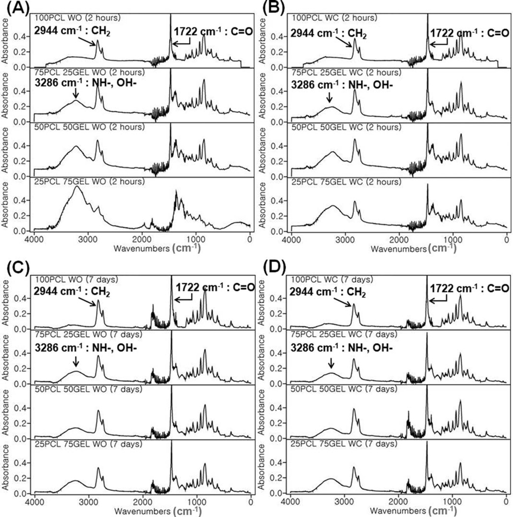
Fourier transform infrared spectroscopy (FTIR) analysis was performed for surface characterization of the composite electrospun scaffolds (PCL/gelatin ratio: 100/0, 75/25, 50/ 50, 25/75) with and without crater-like structures. A set of FTIR spectra was collected after 2 hours, 7 days of degradation of the scaffolds in PBS (Fig. 5). Absorbance peaks at 2944 cm−1 and 1722 cm−1 indicated the presence of alkyl C–H stretch and ester C═O stretch, characteristic bonds observed in PCL; these prominent peaks were consistently observed throughout all of the scaffolds at all time points. Peaks at 3286 cm−1 indicated the presence of amide N–H stretch and alcohol O–H stretch in 75/25, 50/50, and 25/ 75 PCL/gelatin scaffolds. Based on previous work, the presence of the amide group indicated that PCL and gelatin side chains were chemically bonded; this may allow the incorporation of functional groups, such as NH2 and COOH, and enhanced hydrophilicity on the PCL/gelatin scaffolds.24,34 Thus, the composite electrospun scaffolds possessed the biochemical and mechanical properties of ECM by blending gelatin and PCL, thereby providing better cell–scaffold interaction. There was little difference between the scaffolds treated with the gas foaming/salt leaching method and the untreated scaffolds; thus, the citric acid treatment was not intense enough to cause further dissolution of gelatin components from the scaffolds.
FIGURE 5.
FTIR spectra of PCL/gelatin composite electrospun scaffolds with and without crater-like structures. FTIR peaks of (A) PCL/gelatin (100/0, 75/25, 50/50, and 25/75) scaffolds without crater-like structures and (B) with crater-like structures at 2 hours after degradation. (C) The scaffolds without crater-like structures and (D) with crater-like structures at 7 days after degradation.
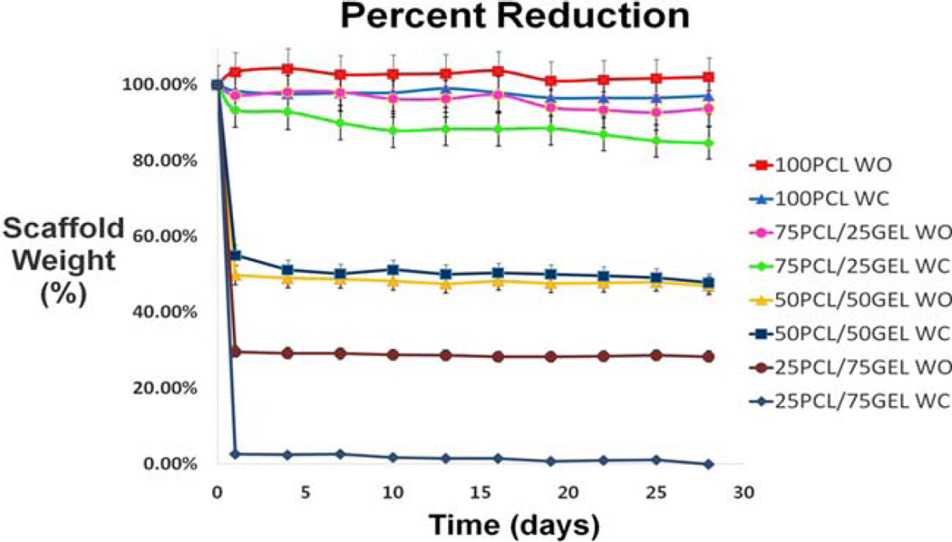
Scaffold degradation was also assessed by weighing scaffolds every 3 days up to 28 days. As seen in Figure 6, PCL/ gelatin scaffolds degraded in a predictable pattern over the 28 day period. The majority of the degradation occurred within the first two days but quickly stabilized. The initial drop in weight for scaffolds with gelatin was expected because the FTIR experiment demonstrated some gelatin removal between 2 hours and 7 days. Since PCL is known to degrade slowly over the course of several months,35,36 it is logical that scaffolds with increased gelatin content degrade more quickly than scaffolds without. In the scaffold groups (PCL/gelatin ratio: 100/0, 75/25, 50/50), there was no significant difference in scaffold degradation between the scaffolds with and without crater-like structures. However, 25/75 PCL/gelatin scaffolds with crater-like structures showed drastic decrease in weight within the first day; this could be that the gas foaming/salt leaching process destabilized the structure of these scaffolds which were mostly composed of gelatin. Then, when the scaffolds were washed with DI water for removal of citric acid and placed in PBS, most of the scaffold was lost. Thus, incorporation of greater than 75% of gelatin resulted in PCL/gelatin scaffolds that were physically too unstable to endure the gas foaming/salt leaching process.
FIGURE 6.
Scaffold degradation by changes in the weight of PCL/gelatin (the ratio: 100/0, 75/25, 50/50, and 25/75) composite electrospun scaffolds with and without crater-like structures.
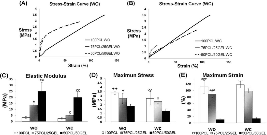
The mechanical characteristics of the composite electrospun scaffolds (PCL/gelatin ratio: 100/0, 75/25, 50/50) with and without crater-like structures, including elastic modulus and stress and strain at break, were evaluated and are summarized in Figure 7 and Table I. As seen in the degradation results, 25/75 PCL/gelatin scaffolds degraded very quickly and also had weak mechanical properties; thus, mechanical characteristics of these samples were excluded from our analysis. As gelatin content increased, there was an evident rise in the elastic modulus and decrease in breaking strain. Thus, scaffolds of 50/50 PCL/gelatin behaved more like brittle materials, while scaffolds with no gelatin acted in an elastic manner [Fig. 7(C,E)]; these trends were also found in another study.34 Alternatively, scaffolds of 75/25 PCL/gelatin had mechanical properties that were very similar to 100% PCL; even though 75/25 PCL/gelatin scaffolds had a higher elastic modulus than 100% PCL, their breaking stresses and strains were comparable [Fig. 7(C–E)]. These results indicate that 75/25 PCL/gelatin scaffolds have synergistic characteristics of both materials; they possess the mechanical stability and elasticity of PCL as well as the bioactive properties of gelatin, thus compensating for the major drawbacks of each material. Most values between the scaffolds with and without crater-like structures did not show statistical difference in their mechanical properties; this indicates that the gas foaming/salt leaching process to generate crater-like structures does not have significant effect on the mechanical properties of the scaffolds, if at least greater than 50% of PCL is incorporated.
FIGURE 7.
Mechanical characteristics of PCL/gelatin composite electrospun scaffolds with and without crater-like structures. (A) Stress–strain curve of PCL/gelatin (100/0, 75/25, and 50/50) scaffolds without crater-like structures and (B) with crater-like structures. (C) Elastic modulus, (D) breaking stress, and (E) breaking strain of the scaffolds with and without crater-like structures. (*p < 0.05 vs. 50/50 PCL/gelatin WO, **p < 0.01 vs. 50/50 PCL/gelatin WO, ×p < 0.05 vs. 50/50 PCL/gelatin WC, ××p < 0.01 vs. 50/50 PCL/gelatin WC, +p < 0.05 vs. 50/50 PCL/gelatin WO, ++p < 0.01 vs. 50/50 PCL/gelatin WO, °p < 0.05 vs. 50/50 PCL/gelatin WC, °°p < 0.01 vs. 50/50 PCL/gelatin WC, ### p <0.001 vs. 50/50 PCL/gelatin WO, −p < 0.001 vs. 50/50 PCL/gelatin WC).
TABLE I.
Elastic Modulus, Breaking Stress, and Breaking Strain of PCL/Gelatin Composite Electrospun Scaffolds With and Without Crater-Like Structures
| Sample (PCL/gelatin ration) | 100/0 WO | 100/0 WC | 75/25 WO | 75/25 W | 50/50 WO | 50/50 WC |
|---|---|---|---|---|---|---|
| Elastic Modulus (MPa) | 3.23 ± 0.92 | 2.46 ± 0.58 | 13.6 ± 0.81 | 4.98 ± 0.42 | 24.8 ± 7.58 | 19.9 ± 3.88 |
| Max stress (Mpa) | 3.34 ± 0. 2 | 2.71 ± 0.78 | 2.72 ± 0.59 | 2.34 ± 0.19 | 1.81 ± 0.23 | 1.26 ± 0.24 |
| Max strain (%) | 111 ± 19.4 | 117.7 ± 9.7 | 87.5 ± 8.26 | 98.5 ± 6.7 | 10.1 ± 1.84 | 13.3 ± 2.88 |
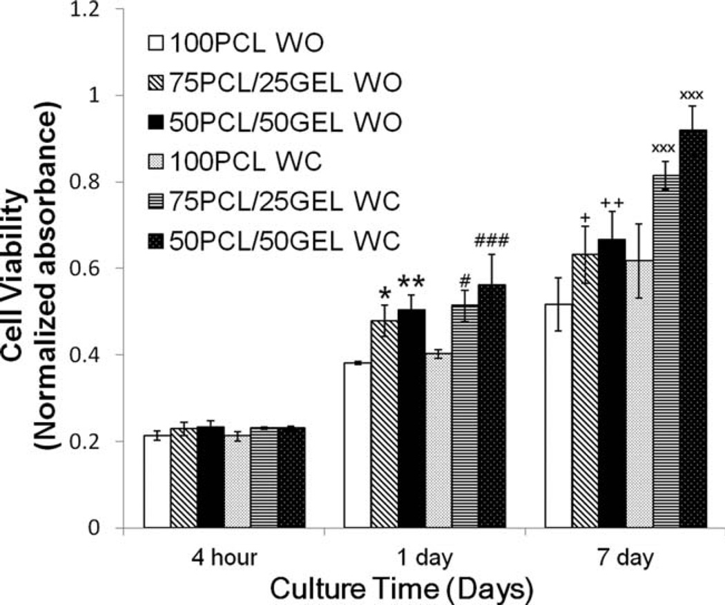
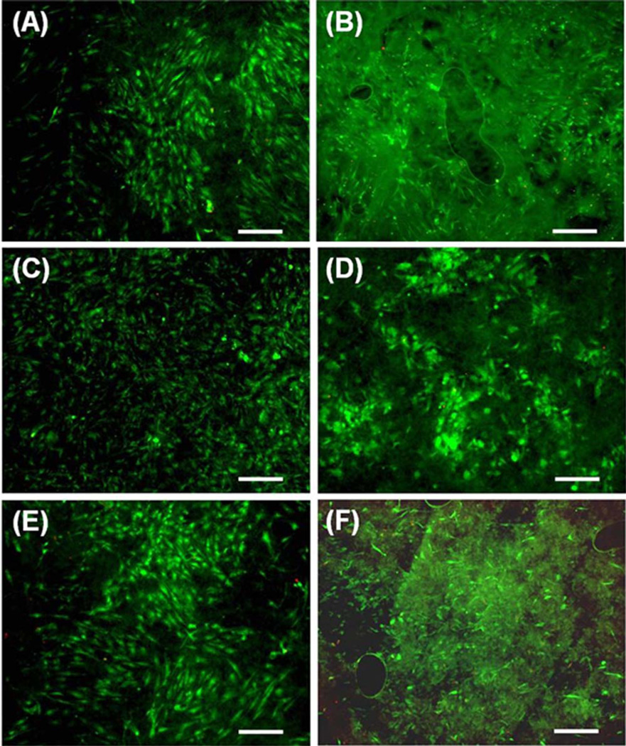
Gelatin is a natural biopolymer obtained from the controlled hydrolysis of collagen, a major ECM component, and it has similarities in amino acid composition, and to some extent in structure to collagen. Incorporation of gelatin into PCL nanofibers can enhance cell–scaffold interactions by mediating cell-adhesive ECM components which affect cellular behaviors such as cell proliferation, migration, and function.24,37–40 Cellular behaviors were studied using human mesenchymal stem cells (hMSCs) seeded on the composite electrospun scaffolds (PCL/gelatin ratio: 100/0, 75/25, 50/ 50), with and without crater-like structures. MSCs are multipotent stromal cells which can differentiate into various cell types, such as chondrocytes, osteoblasts, and adipocytes; they have great potential for clinical applications in regenerative therapy due to their differentiation capabilities, secretion of multiple bioactive molecules, and immunomodulatory functions.41 Proliferation of hMSCs on the composite electrospun scaffolds was quantified using an MTS assay, as shown in Figure 8. While there was little difference in initial cell attachment after 4 hours, a significant transformation took place over one week. After 1 day, there was a substantial increase in proliferation on the scaffolds containing gelatin and there was not much difference between the scaffolds with and without crater-like structures. However, after 7 days, scaffolds with crater-like structures had a substantial amount of cell proliferation in comparison to scaffolds with-out crater-like structures. While the presence of gelatin significantly enhanced cell proliferation after 1 and 7 days, the amount of incorporated gelatin (25 and 50 wt % ratios) did not cause significant difference. These results support that gelatin incorporated composite electrospun scaffolds can increase hMSC proliferation; enhanced cell proliferation has also been demonstrated in other cell types such as mouse nerve stem cell and rabbit cardiomyocytes.24,42 Since a difference in cell proliferation between the scaffolds with and without crater-like structures was seen 7 days after seeding, these results support the hypothesis that crater-like structures improve cell proliferation on our composite scaffolds; it can be reasoned that cells infiltrated the scaffold throughout the crater-like structures between 1 and 7 days, thereby allowing further cell migration and proliferation compared with the scaffolds without crater-like structures. In addition, to test cell viability and visualize the cell attachment onto the scaffolds (PCL/gelatin ratio: 100/0, 75/25, 50/50), a LIVE/ DEAD cell viability assay was performed. The fluorescent hMSC images are shown in Figure 9. After 7 days, most cells still displayed their viability with fluorescence and also were thoroughly spread on all scaffolds. The cells were most easily seen on the scaffolds without crater-like structures. Since the crater-like structures provide a 3D aspect to the surface of the scaffold, it was slightly difficult to visualize cell attachment on the electrospun scaffolds. It may also be explained by the hypothesis that the increased porosity of scaffolds with craters would cause a greater amount of cell infiltration into the center of the scaffolds; then cells inside the scaffolds with craters are likely to be the cause of the poor distinguishability of cell morphology in the LIVE/DEAD images. Therefore, to confirm our hypothesis, a cell infiltration test on the scaffolds was performed.
FIGURE 8.
hMSC proliferation on PCL/gelatin (the ratio: 100/0, 75/25, and 50/50) composite electrospun scaffolds with and without craterlike structures after 4 hours, 1 day, and 7 days of cell seeding measured by an MTS assay (*p < 0.05 vs. 100/0 PCL/gelatin WO at 1 day, **p < 0.01 vs. 100/0 PCL/gelatin WO at 1 day, #p < 0.05 vs. 100/0 PCL/ gelatin WC at 1 day, ###p < 0.001 vs. 100/0 PCL/gelatin WC at 1 day, +p < 0.05 vs. 100/0 PCL/gelatin WO at 7 day, ++p < 0.01 vs. 100/0 PCL/ gelatin WO at 7 day, ×××p < 0.001 vs. 100/0 PCL/gelatin WC at 7 day).
FIGURE 9.
Live/dead assay images of hMSCs on PCL/gelatin composite electrospun scaffolds with and without crater-like structures after 7 days of cell seeding. (A) hMSCs on 100/0 PCL/gelatin scaffold without crater-like structures and (B) with crater-like structures. (C) hMSCs on 75/25 PCL/gelatin scaffold without crater-like structures and (D) with crater-like structures. (E) hMSCs on 50/50 PCL/gelatin scaffold without crater-like structures and (F) with crater-like structures. (Scale bar = 300 µm).
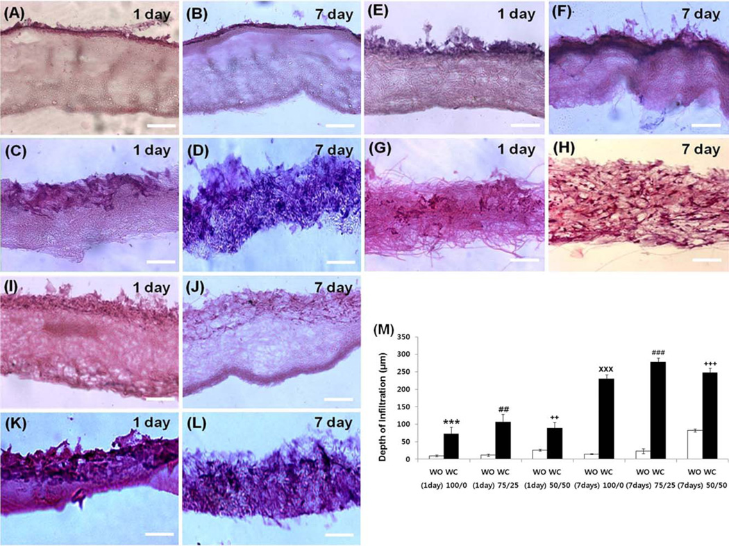
To demonstrate whether porous crater-like structures allow cell infiltration, histological cryosectioned images of hMSC penetration through the composite electrospun scaffolds (PCL/gelatin ratio: 100/0, 75/25, 50/50) were analyzed by hematoxylin and eosin (H&E) staining (Fig. 10). After 1 day from cell seeding, the scaffolds with crater-like structures in all PCL/gelatin ratios displayed hMSC penetration, but the penetrated cells did not spread through the whole sectioned area within the scaffolds [Fig. 10(C,G, K); the depth of infiltration was 100/0: 78.386 19.68 µm, 75/ 25: 106.98 ± 21.93 µm, and 50/50: 89.34 ± 16.37 µm, respectively]. On the contrary, the scaffolds without craterlike structures did not allow hMSC penetration through the scaffolds, and most cells were only located on the surface of the scaffolds [Fig. 10(A, E, I); the depth of infiltration was 100/0: 10.02 ± 2.53 µm, 75/25: 11.49 ± 3.33 µm, and 50/ 50: 23.07 ± 6.89, respectively]. After 7 days, the scaffolds with crater-like structures showed well-spread hMSCs throughout the scaffolds, which demonstrated that further cell migration and proliferation occurred through the interconnected porous spaces within the scaffolds between 1 and 7 days [Fig. 10(D, H, L); the depth of infiltration was 100/0: 230.2 ± 13.14 µm, 75/25: 277.4 ± 3.33 µm, and 50/ 50: 247.89 ± 12.28 µm, respectively]. In comparison, most hMSCs were still not able to penetrate through the scaffolds (PCL/gelatin ratio: 100/0, 75/25) without crater-like structures [Fig. 10B,F); the depth of infiltration was 100/0: 14.75 ± 1.35 µm, and 75/25: 23.1 ± 6.89 µm, respectively]. 50/50 PCL/gelatin scaffold without crater-like structures presented slightly further cell penetration which might be due to gelatin dissolution, but not as much as the groups with crater-like structures [Fig. 10(J); the depth of infiltration was 50/50: 82.64 ± 12.28 µm]. The cell infiltration results demonstrated that the PCL/gelatin composite electrospun scaffolds with crater-like structures showed a significantly higher affinity for cell infiltration compared with those without crater-like structures [Fig. 10(M)]. The results also supported the hypothesis that the scaffolds with crater-like structures had high cell proliferation (MTS) and visualization difficulty in LIVE/DEAD fluorescent images after 7 days. This may be explained by the hypothesis that the surface craters stimulated initial cell penetration, and the loosely packed nanofiber networks within the scaffold enhanced further cell proliferation and distribution throughout the scaffold. In addition, the results showed improvement compared with the electrospun scaffolds made with conventional salt leaching techniques; the sodium chloride leaching method provided more enclosed cavities which limited vertical cellular infiltration and distribution throughout the scaffold (the maximum depth of infiltration was approximately 160 µm for 3 weeks of culture).15 Since cells were able to proliferate into the scaffolds with crater-like structures more easily, it stands to reason that the gas foaming/ salt leaching technique for creating more interconnected crater-like pores may greatly enhance the efficacy of composite electrospun scaffolds with a 3D ECM-mimicking microenvironment. This architecture is significant for enhancing engraftment of implanted cells with surrounding tissues, since living tissue cells exist in 3D microenvironments with intricate cell–cell and cell–ECM interactions and complex nutrient and cell transfer dynamics. Further characterization of the 3D properties of the interconnected craterlike structures within the scaffold will be studied for future 3D culture application of these scaffolds.
FIGURE 10.
hMSC infiltration on PCL/gelatin composite electrospun scaffolds with and without crater-like structures after 1 day and 7 days of cell seeding imaged by H&E staining. (A) hMSCs on 100/0 PCL/gelatin scaffold without crater-like structures after 1 day and (B) after 7 days. (C) hMSCs on 100/0 PCL/gelatin scaffold with crater-like structures after 1 day and (D) after 7 days. (E) hMSCs on 75/25 PCL/gelatin scaffold without crater-like structures after 1 day and (F) after 7 days. (G) hMSCs on 75/25 PCL/gelatin scaffold with crater-like structures after 1 day and (H) after 7 days. (I) hMSCs on 50/50 PCL/gelatin scaffold without crater-like structures after 1 day and (J) after 7 days. (K) hMSCs on 50/50 PCL/gelatin scaffold with crater-like structures after 1 day and (L) after 7 days (Scale bar = 100 µm). (M) The depth of hMSC infiltration. (WO: the scaffolds without crater-like structures, WC: the scaffolds with crater-like structures), (***p < 0.001 vs. 100/0 PCL/gelatin WO at 1 day, ##p < 0.01 vs. 75/25 PCL/gelatin WO at 1 day, ++p < 0.01 vs. 50/50 PCL/gelatin WO at 1 day, ×××p < 0.001 vs. 100/0 PCL/gelatin WO at 7 day, ###p < 0.001 vs. 75/25 PCL/ gelatin WO at 7 day, and +++p < 0.001 vs. 50/50 PCL/gelatin WO at 7 day).
CONCLUSION
In conclusion, we fabricated PCL/gelatin composite electrospun scaffolds with crater-like structures and characterized their material properties and biocompatibility. Cater-like structures endowed the electrospun scaffold with more large pores and higher porosity than the conventional electrospun fibrous network, which successfully enhanced cellular infiltration and proliferation throughout the scaffold. Gelatin incorporation into PCL provided scaffolds with bioactivity and structural stability. Therefore, these characteristics of the composite scaffold with crater-like structures enable it to structurally and biochemically replicate the 3D ECM microenvironment, which provides a novel solution to the current challenges of electrospun scaffolds.
Supplementary Material
Acknowledgments
The authors acknowledge the efforts of William Monroe and Dr. Robin Foley in SEM imaging lab. We express thanks to the Center for Metabolic Bone Disease histological facility for the use of the cryotome equipment.
Contract grant sponsor: Alabama EPSCoR Graduate Scholar fellowship funded by NSF
Contract grant sponsor: NIBIB; contract grant number: 1R03EB017344-01
Contract grant sponsor: NSF career award; contract grant number: CBET-0952974
Contract grant sponsor: NIDDK grant; contract grant number: 1DP3DK094346-01
Contract grant sponsor: NHLBI; contract grant number: 1R01HL125391-01
Footnotes
Additional Supporting Information may be found in the online version of this article.
REFERENCES
- 1.Teti A. Regulation of cellular functions by extracellular matrix. J Am Soc Nephrol. 1992;2:S83–S87. doi: 10.1681/ASN.V210s83. [DOI] [PubMed] [Google Scholar]
- 2.Daley WP, Peters SB, Larsen M. Extracellular matrix dynamics in development and regenerative medicine. J Cell Sci. 2008;121:255–264. doi: 10.1242/jcs.006064. [DOI] [PubMed] [Google Scholar]
- 3.Streuli C. Extracellular matrix remodelling and cellular differentiation. Curr Opin Cell Biol. 1999;11:634–640. doi: 10.1016/s0955-0674(99)00026-5. [DOI] [PubMed] [Google Scholar]
- 4.Causa F, Netti PA, Ambrosio L. A multi-functional scaffold for tissue regeneration: The need to engineer a tissue analogue. Biomaterials. 2007;28:5093–5099. doi: 10.1016/j.biomaterials.2007.07.030. [DOI] [PubMed] [Google Scholar]
- 5.Badylak SF. The extracellular matrix as a scaffold for tissue reconstruction. Semin Cell Dev Biol. 2002;13:377–383. doi: 10.1016/s1084952102000940. [DOI] [PubMed] [Google Scholar]
- 6.Pham QP, Sharma U, Mikos AG. Electrospinning of polymeric nanofibers for tissue engineering applications: A review. Tissue Eng. 2006;12:1197–1211. doi: 10.1089/ten.2006.12.1197. [DOI] [PubMed] [Google Scholar]
- 7.van Apeldoorn AA, Aksenov Y, Stigter M, Hofland I, de Bruijn JD, Koerten HK, Otto C, Greve J, van Blitterswijk CA. Parallel high-resolution confocal Raman SEM analysis of inorganic and organic bone matrix constituents. J R Soc Interface. 2005;2:39–45. doi: 10.1098/rsif.2004.0018. [DOI] [PMC free article] [PubMed] [Google Scholar]
- 8.Zhang Y, Venugopal JR, El-Turki A, Ramakrishna S, Su B, Lim CT. Electrospun biomimetic nanocomposite nanofibers of hydroxyapatite/chitosan for bone tissue engineering. Biomaterials. 2008;29:4314–4322. doi: 10.1016/j.biomaterials.2008.07.038. [DOI] [PubMed] [Google Scholar]
- 9.Tortelli F, Cancedda R. Three-dimensional cultures of osteogenic and chondrogenic cells: A tissue engineering approach to mimic bone and cartilage in vitro. Eur Cells Mater. 2009;17:1–14. doi: 10.22203/ecm.v017a01. [DOI] [PubMed] [Google Scholar]
- 10.Zhu X, Cui W, Li X, Jin Y. Electrospun fibrous mats with high porosity as potential scaffolds for skin tissue engineering. Biomacromolecules. 2008;9:1795–1801. doi: 10.1021/bm800476u. [DOI] [PubMed] [Google Scholar]
- 11.Prabhakaran MP, Venugopal JR, Ramakrishna S. Mesenchymal stem cell differentiation to neuronal cells on electrospun nanofibrous substrates for nerve tissue engineering. Biomaterials. 2009;30:4996–5003. doi: 10.1016/j.biomaterials.2009.05.057. [DOI] [PubMed] [Google Scholar]
- 12.Blakeney BA, Tambralli A, Anderson JM, Andukuri A, Lim DJ, Dean DR, Jun HW. Cell infiltration and growth in a low density, uncompressed three-dimensional electrospun nanofibrous scaffold. Biomaterials. 2011;32:1583–1590. doi: 10.1016/j.biomaterials.2010.10.056. [DOI] [PMC free article] [PubMed] [Google Scholar]
- 13.Rnjak-Kovacina J, Weiss AS. Increasing the pore size of electro-spun scaffolds. Tissue Eng Part B Rev. 2011;17:365–372. doi: 10.1089/ten.teb.2011.0235. [DOI] [PubMed] [Google Scholar]
- 14.Liu H, Roy K. Biomimetic three-dimensional cultures significantly increase hematopoietic differentiation efficacy of embryonic stem cells. Tissue Eng. 2005;11:319–330. doi: 10.1089/ten.2005.11.319. [DOI] [PubMed] [Google Scholar]
- 15.Nam J, Huang Y, Agarwal S, Lannutti J. Improved cellular infiltration in electrospun fiber via engineered porosity. Tissue Eng. 2007;13:2249–2257. doi: 10.1089/ten.2006.0306. [DOI] [PMC free article] [PubMed] [Google Scholar]
- 16.Ekaputra AK, Prestwich GD, Cool SM, Hutmacher DW. Combining electrospun scaffolds with electrosprayed hydrogels leads to three-dimensional cellularization of hybrid constructs. Biomacro-molecules. 2008;9:2097–2103. doi: 10.1021/bm800565u. [DOI] [PubMed] [Google Scholar]
- 17.Ki CS, Kim JW, Hyun JH, Lee KH, Hattori M, Rah DK, Park YH. Electrospun three-dimensional silk fibroin nanofibrous scaffold. J Appl Polym Sci. 2007;106:3922–3928. [Google Scholar]
- 18.Jun HW, West JL. Endothelialization of microporous YIGSR/PEG-modified polyurethaneurea. Tissue Eng. 2005;11:1133–1140. doi: 10.1089/ten.2005.11.1133. [DOI] [PubMed] [Google Scholar]
- 19.Tambralli A, Blakeney B, Anderson J, Kushwaha M, Andukuri A, Dean D, Jun HW. A hybrid biomimetic scaffold composed of electrospun polycaprolactone nanofibers and self-assembled peptide amphiphile nanofibers. Biofabrication. 2009;1:025001. doi: 10.1088/1758-5082/1/2/025001. [DOI] [PMC free article] [PubMed] [Google Scholar]
- 20.Andukuri A, Kushwaha M, Tambralli A, Anderson JM, Dean DR, Berry JL, Sohn YD, Yoon YS, Brott BC, Jun HW. A hybrid biomimetic nanomatrix composed of electrospun polycaprolactone and bioactive peptide amphiphiles for cardiovascular implants. Acta Biomater. 2011;7:225–233. doi: 10.1016/j.actbio.2010.08.013. [DOI] [PMC free article] [PubMed] [Google Scholar]
- 21.Yang F, Murugan R, Wang S, Ramakrishna S. Electrospinning of nano/micro scale poly(L-lactic acid) aligned fibers and their potential in neural tissue engineering. Biomaterials. 2005;26:2603–2610. doi: 10.1016/j.biomaterials.2004.06.051. [DOI] [PubMed] [Google Scholar]
- 22.Xin X, Hussain M, Mao JJ. Continuing differentiation of human mesenchymal stem cells and induced chondrogenic and osteogenic lineages in electrospun PLGA nanofiber scaffold. Biomateri-als. 2007;28:316–325. doi: 10.1016/j.biomaterials.2006.08.042. [DOI] [PMC free article] [PubMed] [Google Scholar]
- 23.Guarino V, Alvarez-Perez M, Cirillo V, Ambrosio L. hMSC interaction with PCL and PCL/gelatin platforms: A comparative study on films and electrospun membranes. J Bioact Compat Polym. 2011;26:144–160. [Google Scholar]
- 24.Ghasemi-Mobarakeh L, Prabhakaran MP, Morshed M, Nasr-Esfahani MH, Ramakrishna S. Electrospun poly(epsilon-caprolactone)/gelatin nanofibrous scaffolds for nerve tissue engineering. Biomaterials. 2008;29:4532–4539. doi: 10.1016/j.biomaterials.2008.08.007. [DOI] [PubMed] [Google Scholar]
- 25.Park J-S, Choi J-B, Jo S-Y, Lim Y-M, Gwon H-J, Khil MS, Nho Y-C. Characterization and structure analysis of PLGA/collagen nanofibrous membranes by electrospinning. J Appl Polym Sci. 2012;125:E595–E603. [Google Scholar]
- 26.Koh HS, Yong T, Chan CK, Ramakrishna S. Enhancement of neurite outgrowth using nano-structured scaffolds coupled with laminin. Biomaterials. 2008;29:3574–3582. doi: 10.1016/j.biomaterials.2008.05.014. [DOI] [PubMed] [Google Scholar]
- 27.Lemmouchi Y, Schacht E. Preparation and in vitro evaluation of biodegradable poly (ε-caprolactone-co-D, L lactide) (X–Y) devices containing tryparocidal drugs. J Control Release. 1997;45:227–233. [Google Scholar]
- 28.Lo HY, Kuo HT, Huang YY. Application of polycaprolactone as an anti-adhesion biomaterial film. Artif Organs. 2010;34:648–653. doi: 10.1111/j.1525-1594.2009.00949.x. [DOI] [PubMed] [Google Scholar]
- 29.Woodruff MA, Hutmacher DW. The return of a forgotten polymer—Polycaprolactone in the 21st century. Prog Polym Sci. 2010;35:1217–1256. [Google Scholar]
- 30.Pulieri E, Chiono V, Ciardelli G, Vozzi G, Ahluwalia A, Domenici C, Vozzi F, Giusti P. Chitosan/gelatin blends for biomedical applications. J Biomed Mater Res Part A. 2008;86:311–322. doi: 10.1002/jbm.a.31492. [DOI] [PubMed] [Google Scholar]
- 31.Johns P, Courts A. The Science and Technology of Gelatin. London: Academic Press; 1977. [Google Scholar]
- 32.Williams C, Liao J, Joyce EM, Wang B, Leach JB, Sacks MS, Wong JY. Altered structural and mechanical properties in decellularized rabbit carotid arteries. Acta Biomater. 2009;5:993–1005. doi: 10.1016/j.actbio.2008.11.028. [DOI] [PMC free article] [PubMed] [Google Scholar]
- 33.Zhong S, Zhang Y, Lim CT. Fabrication of large pores in electrospun nanofibrous scaffolds for cellular infiltration: A review. Tissue Eng Part B Rev. 2012;18:77–87. doi: 10.1089/ten.TEB.2011.0390. [DOI] [PubMed] [Google Scholar]
- 34.Zhang Y, Ouyang H, Lim CT, Ramakrishna S, Huang Z-M. Electro-spinning of gelatin fibers and gelatin/PCL composite fibrous scaffolds. J Biomed Mater Res Part B: Appl Biomater. 2005;72B:156–165. doi: 10.1002/jbm.b.30128. [DOI] [PubMed] [Google Scholar]
- 35.Bolgen N, Menceloglu YZ, Acatay K, Vargel I, Piskin E. In vitro and in vivo degradation of non-woven materials made of poly(epsilon-caprolactone) nanofibers prepared by electrospinning under different conditions. J Biomater Sci Polym Ed. 2005;16:1537–1555. doi: 10.1163/156856205774576655. [DOI] [PubMed] [Google Scholar]
- 36.Johnson J, Niehaus A, Nichols S, Lee D, Koepsel J, Anderson D, Lannutti J. Electrospun PCL in vitro: A microstructural basis for mechanical property changes. J Biomater Sci Polym Ed. 2009;20:467–481. doi: 10.1163/156856209X416485. [DOI] [PubMed] [Google Scholar]
- 37.Ji W, Yang F, Ma J, Bouma MJ, Boerman OC, Chen Z, van den Beucken JJ, Jansen JA. Incorporation of stromal cell-derived factor-1alpha in PCL/gelatin electrospun membranes for guided bone regeneration. Biomaterials. 2013;34:735–745. doi: 10.1016/j.biomaterials.2012.10.016. [DOI] [PubMed] [Google Scholar]
- 38.Zheng R, Duan H, Xue J, Liu Y, Feng B, Zhao S, Zhu Y, Liu Y, He A, Zhang W, Liu W, Cao Y, Zhou G. The influence of Gelatin/PCL ratio and 3-D construct shape of electrospun membranes on cartilage regeneration. Biomaterials. 2014;35:152–164. doi: 10.1016/j.biomaterials.2013.09.082. [DOI] [PubMed] [Google Scholar]
- 39.Yang X, Yang F, Walboomers XF, Bian Z, Fan M, Jansen JA. The performance of dental pulp stem cells on nanofibrous PCL/gelatin/nHA scaffolds. J Biomed Mater Res a. 2010;93:247–257. doi: 10.1002/jbm.a.32535. [DOI] [PubMed] [Google Scholar]
- 40.Chong EJ, Phan TT, Lim IJ, Zhang YZ, Bay BH, Ramakrishna S, Lim CT. Evaluation of electrospun PCL/gelatin nanofibrous scaffold for wound healing and layered dermal reconstitution. Acta Biomater. 2007;3:321–330. doi: 10.1016/j.actbio.2007.01.002. [DOI] [PubMed] [Google Scholar]
- 41.Wang S, Qu X, Zhao RC. Clinical applications of mesenchymal stem cells. J Hematol Oncol. 2012;5:19. doi: 10.1186/1756-8722-5-19. [DOI] [PMC free article] [PubMed] [Google Scholar]
- 42.Prabhakaran MP, Kai D, Ghasemi-Mobarakeh L, Ramakrishna S. Electrospun biocomposite nanofibrous patch for cardiac tissue engineering. Biomed Mater. 2011;6:055001. doi: 10.1088/1748-6041/6/5/055001. [DOI] [PubMed] [Google Scholar]
Associated Data
This section collects any data citations, data availability statements, or supplementary materials included in this article.


