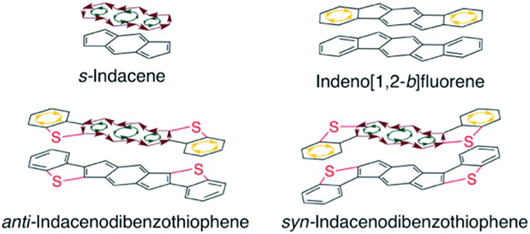
 Exchanging fused benzenes for benzothiophenes results in pronounced antiaromaticity in the indacene core.
Abstract
Indeno[1,2-b]fluorenes (IFs), while containing 4n π-electrons, are best described as two aromatic benzene rings fused to a weakly paratropic s-indacene core. In this study, we find that replacement of the outer benzene rings of an IF with benzothiophenes allows the antiaromaticity of the central s-indacene to strongly reassert itself. Herein we report a combined synthetic, computational, structural, and materials study of anti- and syn-indacenodibenzothiophenes (IDBTs). We have developed an efficient and scalable synthesis for preparation of a series of aryl- and ethynyl-substituted IDBTs. NICS-XY scans and ACID calculations reveal an increasingly antiaromatic core from [1,2-b]IF to anti-IDBT, with syn-IDBT being nearly as antiaromatic as the parent s-indacene. As an initial evaluation, the intermolecular electronic couplings and electronic band structure of a diethynyl anti-IDBT derivative reveal the potential for hole and/or electron transport. OFETs constructed using this molecule show the highest hole mobilities yet achieved for a fully conjugated IF derivative.
Introduction
First predicted by Hückel in 19311 and later proposed by Breslow in 1967,2 antiaromaticity describes conjugated cyclic systems containing 4n π electrons that are destabilized in comparison to a suitable reference compound.3 Many groups have sought to further expand this concept,3a,c,d,4 and the criteria for aromatic and antiaromatic compounds have been succinctly defined by Breslow,3b Krygowski,3e and Wiberg.4i In addition to containing 4n π-electron cyclic conjugation, antiaromatic compounds have decreased delocalization, smaller HOMO–LUMO energy gaps, and increased bond length alternation in comparison to aromatic molecules.3b,e,4i Antiaromatic compounds also exhibit paratropic 1H NMR chemical shifts and large, positive nucleus independent chemical shift (NICS) values.3b,4b,d,5 Although experimental examples of antiaromatic compounds are quite rare, they nonetheless have attracted the attention of chemists due to theoretical interest and potential materials science applications.4e,5b,6
Over the last 20 years, chemists have focused on the rational design of organic electronic materials.7 The synthesis and rigorous optical, electronic, and solid-state characterization of small molecule organic semiconductors has enhanced enormously our understanding of the fundamental principles necessary to design materials for high performing organic light emitting diodes (OLEDs), organic field effect transistors (OFETs), organic photovoltaics (OPVs), or other organic electronic devices.7e–k,8 Highly conjugated polycyclic hydrocarbons (CPHs) are a fascinating class of compounds often utilized in organic electronics due to their desirable photophysical and electronic properties.7a–d,7h–k,9 The study of these CPHs has resulted not only in functional materials, but also provided insight into fundamental chemical principles, such as the nature of the carbon–carbon bond, singlet-biradical character, and aromaticity and antiaromaticity, knowledge that in turn can be applied to designing better performing materials.7a–d,h–k,9a,e,f,10
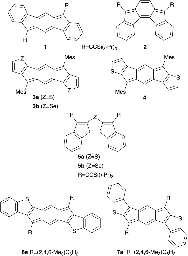
Although acenes are widely used in organic electronics, their susceptibility to oxidative and photolytic degradation has led researchers to explore alternative acene-like topologies.7j,9d,11 Studies on acene-like structures reveal that decreasing the aromaticity within a ring system or the inclusion of antiaromatic rings into materials could greatly improve their electrical conductivity and increase charge mobilities in the solid state.4e,5b,6,12 Recently, indenofluorenes, with their 6–5–6–5–6 fused ring systems and overall 4n π electrons, have received particular interest as indeno[1,2-b]fluorene (1) derivatives show ambipolar charge transport in both single-crystal and thin-film OFETs (Fig. 1).13
Fig. 1. Indeno[1,2-b]fluorene ([1,2-b]IF) 1, indeno[2,1-c]fluorene ([2,1-c IF) 2, anti-indacenodithiophene (anti-IDT) 3a, indacenodiselenophene (IDS) 3b, syn-indacenodithiophene (syn-IDT) 4, diindenothiophene (DI1T) 5a, diindenoselenophene (DIS) 5b, anti-indacenodibenzothiophene (anti-IDBT) 6a, and syn-indacenodibenzothiophene (syn-IDBT) 7a.
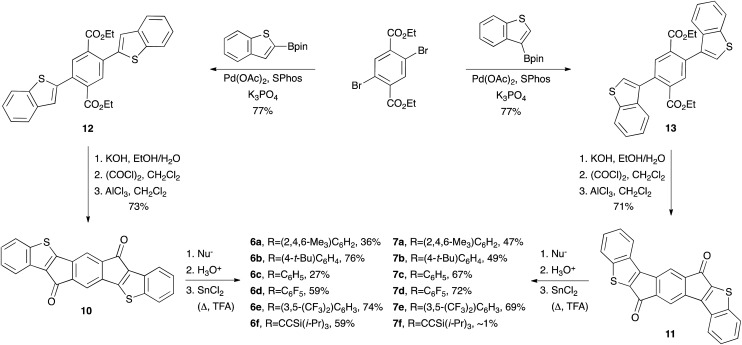
Since 2010, our group14 and others10g,i,13b,15 have investigated compounds based on the indenofluorene (IF) scaffold (IFs 1–7Fig. 1).13a,16 The inclusion of two carbonaceous five-membered rings imparts an intrinsic ability to accept electrons reversibly,16i which in turn has led to the examination of IFs and their derivatives as potential ambipolar and n-type materials. Recently, we explored thieno-fusion on the IF skeleton and published initial reports on the synthesis and characterization of indacenodithiophene and indacenodibenzothiophene (anti-IDT 3a and syn-IDT 4, anti-IDBT 6a and syn-IDBT 7a),16l diindenothienoacenes (DI[n]T 5a),16k and their selenophene analogues (IDS 3b and DIS 5b)16f (Fig. 1). Given the low-lying LUMO levels and small electrochemical energy gaps of IDBTs 6a and 7a, we were keen to further expand the chemistry of these compounds. We also sought to explore more promising crystal morphologies for the IDBTs by varying the substituents at the apical carbon of the five-membered ring. Herein we report a combined synthetic, computational, structural, and materials study of anti-IDBTs 6 and syn-IDBTs 7. We describe in detail the pronounced antiaromaticity of the s-indacene core, the preparation of IDBTs 6b–f and 7b–f (Scheme 1) along with the improved synthesis of their respective precursors (IDBT diones 10 and 11), and finally the respective optical, electrochemical, solid-state, and materials properties of the new compounds.
Scheme 1. Preparation of IDBTs 6a–f and 7a–fvia an improved synthesis of diesters 12 and 13.
Results and discussion
NICS-XY scan computations
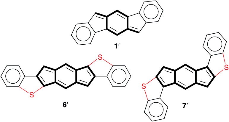
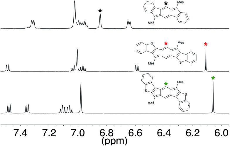
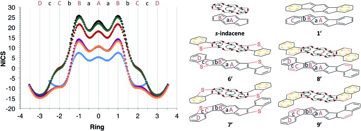
Despite the indenofluorene naming convention (i.e., an indene fused to a fluorene), analysis of the 1H NMR spectrum,16i NICS values and X-ray crystal structure data16a,b of indeno[1,2-b]fluorene (1) reveal that this compound is more accurately described as a benzo-fused para-xylylene derivative (1′, Fig. 2). Both anti-IDBT 6a (6.11 ppm) and syn-IDBT 7a (6.06 ppm) show a significant upfield 1H NMR chemical shift of the central six-membered ring proton when compared with [1,2-b]IF 1 (6.85 ppm) (Fig. 3), suggesting increased paratropicity of the s-indacene core of the IDBTs. Given the difficulty of assessing aromaticity/antiaromaticity simply based on NMR chemical shifts alone, we elected to explore computationally the antiaromaticity of IDBTs 6′ and 7′.
Fig. 2. Molecular structures highlighting the para-xylylene motif in [1,2-b]IF 1′ and the s-indacene motif in IDBTs 6′ and 7′.
Fig. 3. Partial 1H NMR spectra (500 MHz, CD2Cl2, 20 °C) of compounds 1, 6a, and 7a.
Determination of the NICS value offers a means to assess the aromaticity or antiaromaticity of a ring system.4a–d Negative NICS values indicate a diatropic ring current (aromatic), while positive NICS values indicate a paratropic ring current (antiaromatic). Although NICS values are useful for determining local ring currents, they are unable to expound upon global and semi-global ring currents. Recently, Stanger developed the NICS-XY scan, which can be used to explore these types of ring currents (global, semi-global, local, diatropic or paratropic) in flat π-conjugated systems.17
The NICS-XY scans of s-indacene, [1,2-b]IF 1′, anti-IDBT 6′ and syn-IDBT 7′ are shown in Fig. 4, along with those of the isoelectronic hydrocarbon analogues of the IDBTs, namely unknown indacenodinaphthalenes (IDNs) 8′ and 9′. The B3LYP/6-311+G* NICS-XY values were taken 1.7 Å above the molecular plane and employed the σ-only model to take only π contributions into consideration.17,18 The NICS-XY scan of s-indacene shows two strong (25.7 ppm) paratropic ring currents on the five-membered rings (B rings) and a slightly smaller (23.1 ppm) paratropic ring current over the center six-membered ring (A ring). This NICS-XY scan suggests that s-indacene contains a global paratropic ring current as well as local paratropic ring currents over each of the rings with the current over the outer five-membered B rings being the strongest. In contrast, the NICS-XY scan of 1′ reveals two diatropic ring currents (–9.2 ppm) that are clearly visible over the outer most benzene rings (C ring), while the central s-indacene motif is weakly paratropic (largest NICS value of 7.4 ppm). This result further confirms our assertion that [1,2-b]IF 1′ is two aromatic benzene rings fused to a weakly paratropic para-xylylene core.
Fig. 4. NICS-XY scans and induced ring currents of s-indacene (black), [1,2-b]IF 1′ (blue), anti-IDBT 6′ (red), syn-IDBT 7′ (green), anti-IDN 8′ (purple) and syn-IDN 9′ (orange).
The pronounced paratropicity of the s-indacene core of IDBTs 6′ and 7′ is noticeably evident from their respective NICS-XY scans. anti-IDBT 6′ is slightly less paratropic (NICS values of 21.5 ppm on B ring and 18.0 ppm on A ring) than s-indacene while showing an overall similar NICS-XY scan. The NICS-XY scan of the syn-IDBT 7′ core is nearly indistinguishable from that of the parent s-indacene. syn-IDBT 7′ possesses NICS-XY values of 24.9 ppm and 21.9 ppm for the B ring and A ring, respectively, compared with 25.7 and 23.1 ppm for s-indacene. Both 6′ and 7′ have strong, nearly equal diatropic ring currents (–14.3 and –13.3 ppm, respectively) in the outer-most benzene rings (D ring), while the thiophene ring (C ring) of both 6′ and 7′ is clearly non-aromatic with NICS values of 0.07 and 0.11 ppm, respectively. In contrast, the NICS values for the s-indacene core in isoelectronic anti-IDN 8′ and syn-IDN 9′ are roughly half of the IDBT values—B ring and A ring values are 14.0 and 10.5 ppm for 8′ and 12.9 and 10.6 ppm for 9′, respectively, reflecting the competition between the paratropic and diatropic ring currents. The diatropic ring currents in the C and D rings of 8′ and 9′ (8′: –8.7/–14.1, 9′: –9.4/–14.9 ppm, respectively), however, are analogous to the NICS values predicted for the C ring of 1′ and the D ring of 6′ and 7′, as might be expected for the purely hydrocarbon naphthalene unit.
ACID calculations
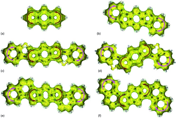
The anisotropy of induced current density (ACID) method19 is used to visualize the ring currents20 for s-indacene, 1′, and 6′–9′ at the TPSSh/SVP level of theory (Fig. 5).21 According to the ACID calculations, the parent s-indacene exhibits strong antiaromatic character (shows a counter-clockwise ring current) (Fig. 5a). A critical isosurface value (CIV) can be assigned to weak points in a cyclic system of delocalized electrons.‡ 22 A high CIV represents strong conjugation, and a low CIV reflects weak delocalization at a critical point. In the case of s-indacene, the isosurface ruptures at a CIV of 0.111 (see ESI† for all CIV data). In contrast, the ACID plot for [1,2-b]IF 1′ exhibits a diamagnetic ring current (aromatic) in the outer benzene rings that seem to disturb the paramagnetic ring current of the indacene core (Fig. 5b). The isosurface in the indacene core ruptures earlier (CIV = 0.071) than in that of s-indacene, further confirming that [1,2-b]IF 1′ is weakly paratropic.
Fig. 5. ACID plots of the induced ring currents of (a) s-indacene, (b) indeno[1,2-b]fluorene 1′, (c) anti-IDBT 6′, (d) syn-IDBT 7′, (e) anti-IDN 8′ and (f) syn-IDN 9′. Note that the magnetic field is chosen to be orthogonal to the ring planes and pointing towards the viewer.
The ACID plot of anti-IDBT 6′ exhibits diamagnetic ring currents in the outer benzene rings and a strong paratropic ring current in the indacene core (Fig. 5c). Similarly, the ACID plot of syn-IDBT 7′ also exhibits diamagnetic ring currents in the outer benzene rings and a strong paratropic ring current in the indacene core (Fig. 5d). The isosurface of the s-indacene core for 6′ ruptures at a CIV of 0.084 and at a CIV of 0.099 for syn-IDBT 7′. The trend of CIVs nicely matches the trend seen in the NICS-XY scans, namely, the antiaromaticity of the s-indacene core increases from anti-IDBT 6′ to syn-IDBT 7′ with 7′ being nearly as antiaromatic as the parent s-indacene. For IDNs 8′ and 9′ (Fig. 5e and f) the CIV are 0.076 and 0.074, respectively, falling in-between the values of 1′ and 6′/7′, analogous to the NICS-XY scans (see ESI† for more details).
The combined 1H NMR data, NICS-XY scans, and ACID results paint a fairly clear picture of the antiaromatic nature of IDBTs 6′ and 7′. The NICS-XY and ACID calculations also reconfirm the strong paratropicity of s-indacene while further solidifying our argument that this same structural unit within [1,2-b]IF 1′ be regarded as weakly paratropic. All three data sets show increasing antiaromaticity of the tricyclic core from [1,2-b]IF 1′ to IDNs 8′ and 9′, then to anti-IDBT 6′ and syn-IDBT 7′ with the parent s-indacene showing the highest degree of paratropicity. Direct benzannelation of the indacene core (as in 1′) strongly reduces the antiaromaticity of the indacene unit because the diatropic (clockwise) ring current of benzene encounters the paratropic (counter-clockwise) current of the indacene at the bond of annelation (and the benzene obviously dominates the conflicting currents). This conflict is mitigated somewhat in naphtho-fused IDNs 8′ and 9′; however, the thiophene rings in 6′ and 7′ essentially isolate the conflicting ring currents, leaving the paratropic s-indacene current almost intact. Given these results, we believe that IDBTs 6′ and 7′ are best described as substituted s-indacenes with the appended phenyl groups planarized by thioether linkages (Fig. 2, 4). Although not a significant difference, calculations at the B3LYP/cc-pVDZ level of theory indicate that 6′ is more stable than 7′ by 1.29 kcal mol–1.
Synthesis
Encouraged by the computational studies, we set out to prepare new derivatives of 6 and 7. The typical strategy for the synthesis of IFs and their related congeners is addition of a nucleophile to the corresponding dione followed by a SnCl2-mediated reductive dearomatization. Our initial report on the assembly of diones 10 and 11 utilized a Stille cross-coupling to construct key precursors 12 and 13, respectively.16l We have improved the preparation of diesters 12 and 13 by employing a Suzuki–Miyaura cross-coupling (Scheme 1), allowing us to selectively synthesize diones 10 or 11 on gram scale from commercially available starting materials without the use of column chromatography. Concurrent work on a separate project suggested that performing the final SnCl2-mediated reduction under rigorous anhydrous and anaerobic conditions could induce a significant increase in product yield. As a prototypical example, the synthesis of compound 6f proceeds in 12% yield when using N2-sparged toluene as received, whereas performing the final reduction under rigorous anaerobic and anhydrous conditions furnishes 6f in 59% yield. This strategy was extended to a series of diaryl- and diethynyl-substituted IDBTs possessing electron-withdrawing or donating groups (6a–f, 7a–f).§ The reduction for electron-withdrawing arenes such as (6d, e and 7d, e) was sluggish and required the addition of a small amount of trifluoroacetic acid for the reaction to proceed smoothly.
Optoelectronic properties
Fig. 6 shows the electronic absorption spectra for IDBTs 6a–f and 7a–f. These data, along with the experimentally determined electrochemical data, are summarized in Table 1. anti-IDBTs 6a–f have a major absorption centered around 375 nm (3.31 eV) while syn-IDBTs 7a–f exhibit a major absorption from 330 to 300 nm (3.76 to 4.13 eV). As with the previously reported mesityl derivatives 6a and 7a, 6b–f and 7b–f show low energy absorptions ranging from 683 to 643 nm (1.82 to 1.93 eV). Time-dependent density functional theory (TDDFT) calculations at the B3LYP/cc-pVDZ level of theory show that these S0 → S2 one-electron excitations are predominantly HOMO → LUMO or HOMO–1 → LUMO transitions, depending on the nature of the substituent appended to the IDBT backbone (see ESI† for more details).
Fig. 6. Electronic absorption spectra of anti-IDBTs 6a–f (left) and syn-IDBTs 7a–f (right) in CH2Cl2.
Table 1. Electrochemical and optical data for IDBTs 6a–f and 7a–f.
| Compd | Electrochemical |
Optical
a
|
|||||||
| E 1 red (V) | E 2 red (V) | E 1 ox (V) | E HOMO (eV) | E LUMO (eV) | E gap (eV) | λ max (nm) | λ onset (nm) | E gap (eV) | |
| 6a b , d | –0.80 | –1.62 c | 0.92 | –5.56 | –3.84 | 1.72 | 618 | 649 | 1.91 |
| 6b b , e | –0.64 | –1.40 c | 1.01 | –5.56 | –4.00 | 1.65 | 648 | 685 | 1.81 |
| 6c b , d | –0.61 | –1.32 c | 1.08 c | –5.72 | –4.03 | 1.69 | 643 | 678 | 1.83 |
| 6d b , f | –0.41 | –1.15 | 1.10 | –5.74 | –4.23 | 1.52 | 664 | 702 | 1.77 |
| 6e b , e | –0.35 | –0.97 | 1.36 c | –6.00 | –4.29 | 1.71 | 658 | 694 | 1.79 |
| 6f b , f | –0.46 | –1.24 c | 0.97 | –5.61 | –4.18 | 1.44 | 682 | 709 | 1.75 |
| 7a b , d | –0.61 | –1.24 c | 0.98 c | –5.62 | –4.03 | 1.59 | 626 | 664 | 1.89 |
| 7b b , e | –0.49 | –1.08 | 1.02 | –5.66 | –4.15 | 1.51 | 673 | 719 | 1.72 |
| 7c b , e | –0.46 | –1.01 | 1.04 c | –5.68 | –4.19 | 1.50 | 665 | 712 | 1.74 |
| 7d b , f | –0.33 | –0.96 | 1.02 | –5.66 | –4.31 | 1.36 | 672 | 715 | 1.74 |
| 7e b , e | –0.16 | –0.64 | 1.29 c | –5.93 | –4.48 | 1.46 | 677 | 722 | 1.72 |
| 7f b , f | –0.37 | –1.03 c | 1.00 | –5.64 | –4.27 | 1.38 | 683 | 718 | 1.73 |
aSpectra were obtained in CH2Cl2. The optical HOMO/LUMO gap/absorbance onset was determined as the intersection of the x-axis and a tangent line passing through the inflection point of the lowest energy absorption.
bCVs were recorded at a scan rate of 50 mV s–1 with a glassy carbon working electrode, a Pt coil counter electrode, and a Ag wire pseudo-reference. Values reported as the half-wave potential (vs. SCE) using the Fc/Fc+ couple (0.46 V in CH2Cl2, 0.56 V in THF) as an internal standard. HOMO and LUMO energy levels in eV were approximated using SCE = –4.68 eV vs. vacuum and E1/2 values for reversible processes or Ep values for irreversible processes.
cReported as V at peak current, not half-wave potential.
d1–5 mM of analyte in 0.1 M Bu4NOTf/CH2Cl2.
e1–5 mM of analyte in 0.1 M Bu4NBF4/THF.
f1–5 mM of analyte in 0.1 M Bu4NBF4/CH2Cl2.
Interestingly, there are differences in the low energy absorptions of the anti-IDBTs compared to the syn-IDBTs. The anti-IDBTs (6b–f) have a λmax ranging from 643–682 nm (39 nm [0.11 eV] range) whereas the syn-IDBTs (7b–f) have a λmax ranging from 665 to 683 nm (18 nm [0.04 eV] range). This difference is reflected in the onset of absorbance for the two isomers: the anti isomers have an onset of absorption ranging from 678 to 709 nm (31 nm [0.07 eV] range) while the syn isomers have an onset of absorption ranging from 712 to 722 nm (10 nm [0.03 eV] range). From the computational data, however, one cannot ascertain ‘more variability’ in one IDBT family versus the other. For the computed S0 → S1 excitation energies, the range for IDBTs 6a–f is 0.27 eV while that in IDBTs 7a–f is 0.25; a similar story unfolds for the adiabatic ionization potentials (see below), where the range for IDBTs 6a–f is 0.60 eV while that for IDBTs 7a–f is 0.58 eV. Moreover, the trends in the S0 → S1 transition energies and adiabatic ionization potentials are nearly identical for both families.
As observed with all other reported IFs, IDBTs 6a–f and 7a–f are non-emissive, a fact consistent with the lack of oscillator strength (f) determined for the S0 → S1 transitions in all TDDFT calculations on the IDBTs.23 The S0 → S1 excitations in the IDBTs consist of a one-electron transition between orbitals of (nearly) the same symmetry (bg, based on the C2h symmetry of 6′ and 7′, see below), making the excitations orbitally forbidden.
As was seen in our study of mesityl-substituted [1,2-b]IF 1, both 6a and 7a are hypsochromically shifted (ca. ∼40 nm) from 6b–f and 7b–f. This is easily explained by examination of the crystal structures of 7avs.7b. The mesityl groups of 6a and 7a are nearly orthogonal to the core of the molecule with a dihedral angle between the average planes of the aryl group and IDBT core of 75.0° and 59.6°, respectively, whereas 7b has dihedral angles of 33.2° and 29.3°. The large dihedral angle of the mesityl group to the IDBT core in 6a and 7a limits electronic communication between the orthogonal π systems, effectively limiting the delocalization of the π orbitals of 6a and 7a when compared to the other aryl substituents (see the discussion of the molecular orbitals below for more details).
Electrochemistry
All IDBTs undergo one reversible reduction in solution. A second reduction is observed for all of the IDBTs; however, its reversibility is dependent upon the aryl or ethynyl substituent. IDBTs 6a–f and 7a–f all display an oxidation wave ranging from irreversible to reversible depending on the aryl or ethynyl substituent. Cyclic voltammograms (CVs) of 6b, e, f and 7b, e, f are displayed in Fig. 7 (see the ESI† for CVs of 6a, c, d and 7a, c, d). All electrochemical data are compiled in Table 1. E1red values range from –0.80 to –0.16 V vs. SCE (6a and 7e, respectively) and E1ox values range from 0.92 to 1.36 V vs. SCE (6a and 6e, respectively). Electron-withdrawing groups shift E1red and E1ox to more positive values while electron-donating groups shift E1red and E1ox to more negative values.
Fig. 7. CV data of anti-IDBTs 6b, 6e, and 6f (left) and syn-IDBT 7b, 7e, and 7f (right).
Once again, interesting electronic differences between the syn- and anti-isomers are observed. The CV determined E1red values for the syn-IDBTs are consistently more energetically stabilized when compared to their anti-IDBT counterparts, and the electrochemically determined Egap (E1ox – E1red) is consistently smaller for the syn-IDBTs. The E1red values of the diaryl anti-IDBTs (6a–f) have an average E1red 0.15 eV higher than their syn-IDBT (7a–f) counterparts.¶ As with the optical transitions, the computed ionization potentials (IP) and electron affinities (EA) at the B3LYP/cc-PVDZ level of theory follow the experimental trends quite well (see ESI†), with the syn-IDBTs generally possessing larger EAs (and more energetically stabilized LUMO energies) than the anti-IDBT counterparts with the same chemical functionalization.
Analysis of the frontier molecular orbitals provides insight behind the observed optoelectronic characteristics. Select frontier molecular orbitals for 6′ and 7′, each with C2h symmetry, are given in the ESI.† For each system, the splitting between the HOMO–1 (au symmetry) and HOMO (bg symmetry) is rather small, 0.13 eV for 6′ and 0.26 eV for 7′, with the HOMO energies for 6′ and 7′ nearly identical. The LUMO of 7′, however, is 0.13 eV more energetically stable than that of 6′ (both LUMOs have bg symmetry), a result that already provides insight into the larger EAs/smaller reduction potentials observed for the syn-IDBT series. In both cases, the HOMO and LUMO mainly reside on the carbon framework, with the sulfur playing a larger role in the LUMO of 6′ and the HOMO of 7′. Notably, the various chemical substituents, depending on the relative donor or acceptor strength (and configuration of the phenyl group), impart changes to the molecular orbitals. First, the energetic gap between the HOMO and HOMO–1 is reduced across the full molecular series with respect to the parent 6′ and 7′ species, with the donor substituents in 6b, 6c, and 7b leading to an energetic repositioning of the HOMO and HOMO–1, i.e., the HOMO is the au symmetric orbital in these systems. It may be expected that the donor strength of the mesityl substituents in 6a and 7a could also lead to such an inversion; however, the lack of extension of the HOMO or HOMO–1 onto the phenyl rings, due to the orthogonal orientation of the mesityl units, prevents this from occurring and the frontier orbitals simply become energetically destabilized when compared to 6′ and 7′ through inductive effects. The reordering of the orbitals leads to the varying descriptions of the S0 → S1 and S0 → S2 described above. A combination of wave function delocalization on the phenyl rings and inductive effects due to the fluorine atoms in 6d/7d and 6e/7e lead to large energetic stabilization of the frontier orbitals, and subsequently the larger IPs/smaller oxidation potentials and larger EAs/smaller reduction potentials of these systems versus the other phenyl substituents. The picture differs somewhat when comparing 6f and 7f: in both cases, the LUMO extends onto the ethynyl arm, energetically stabilizing the LUMO when compared to the parent anti- and syn-IDBT systems. In 6f, however, the HOMO and HOMO–1 switch their order and the au parent orbital extends onto the ethynyl arm, destabilizing the HOMO, while this does not appear to be the case in 7f (though the energetic splitting between the HOMO and HOMO–1 is quite small, 0.02 eV). Overall, the molecular orbitals reveal the rather complex interplay between the base anti- and syn-IDBT structures and the nature of the chemical substituents that in turn determine the relative electrochemical and optical characteristics observed experimentally.
Solid-state structures
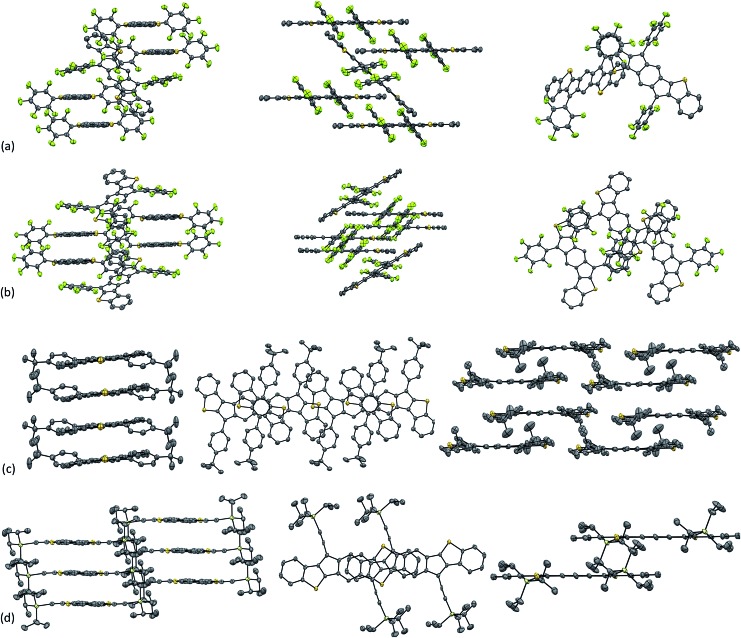
Single crystals of 6f and 7b suitable for X-ray diffraction (XRD) were obtained via the slow diffusion of CH3CN into CHCl3, while single crystals of 6d and 7d were grown via the slow evaporation of a concentrated solution in chlorobenzene at –40 °C. The molecular structures of 6d, f and 7b, d are shown in Fig. 8. As expected, varying the substituents of the IDBT core greatly influences the observed packing motif (Fig. 9). The solid-state morphologies of both 6d and 7d appear to be largely driven by arene/perfluoroarene interactions (Fig. 9a and b). anti-IDBT 6d packs in 1-D chains with a distance between average planes of the IDBT core of 3.48 Å. The perfluorophenyl groups of one 1-D chain are centered over the aromatic aryl group (D ring) of the neighboring chain. The distance between the center of the perfluorophenyl ring and center of the D ring is 3.76 Å, which is in good agreement with the center-to-center distances (3.4–3.8 Å) observed for other 1 : 1 arene/perfluoroarene crystal structures.24 The dihedral angle between the plane of the IDBT core and the plane of the perfluorophenyl ring of 6d is 54.9°, significantly smaller than the dihedral angle between the average plane of the mesityl group and IDBT core of 6a (75.0°).
Fig. 8. Molecular structures of 6f, 6d, 7d, and 7b; hydrogen atoms omitted for clarity. Ellipsoids drawn at 50% probability level.
Fig. 9. Solid state crystal packing diagrams of (a) anti-IDBT 6d, (b) syn-IDBT 7d, (c) syn-IDBT 7b, and (d) anti-IDBT 6f. Hydrogen atoms omitted for clarity. Ellipsoids drawn at 50% probability level.
The molecular structure of syn-IDBT 7d contains three symmetrically independent molecules with two of these forming a 1-D chain. The distance between the average planes of the 1-D chain is 3.57 Å. The third molecule bridges the 1-D chains with the center of the perfluorophenyl rings of the bridging molecule 3.51–3.74 Å from the center of the D ring for the molecules of the 1-D chain. The dihedral angle between the average plane of the perfluorophenyl ring and the plane of the IDBT core ranges from 44.0–47.5°. This dihedral angle is significantly smaller than the same angle observed in 6d and can be explained by a weak S···F interaction.25 The distance between the sulfur of the thiophene ring (C ring) and the nearest fluorine of the perfluorophenyl ring ranges from 2.98–3.03 Å, well below the S–F van der Waals radius of 3.27 Å.
syn-IDBT 7b appears to pack on the cusp between a 1-D and 2-D structure (1-D chain of…B–A–B′…) with distances of 3.49 and 3.42 Å between the average planes (B–A and A–B′, respectively) (Fig. 9c). The close C–S contacts between 1-D columns are 3.60 and 3.51 Å, while the close C–C contacts are 3.55 and 3.45 Å (B–A and A–B′, respectively). The centroids of the IDBT cores are offset by 3.11 and 4.67 Å (B–A and A–B′). Interestingly, there appear to be multiple S–S interactions between the 1-D chains with S–S distances of 3.48, 3.65 and 3.68 Å (S–S van der Walls radius is 3.60 Å).
anti-IDBT 6f packs in 1-D slip-stacked columns with a distance between the average planes of the IDBT core of 3.36 Å and short C–C contacts of 3.36 Å (Fig. 9d). There is a large amount of molecular overlap in the packing of 6f with the center of the outer benzene ring shifted only 1.15 Å from the center of the central s-indacene ring. Given the large overlap and sub-van der Waals C–C contacts in 6f, we elected to focus on this compound for potential device fabrication.
Electronic band structure
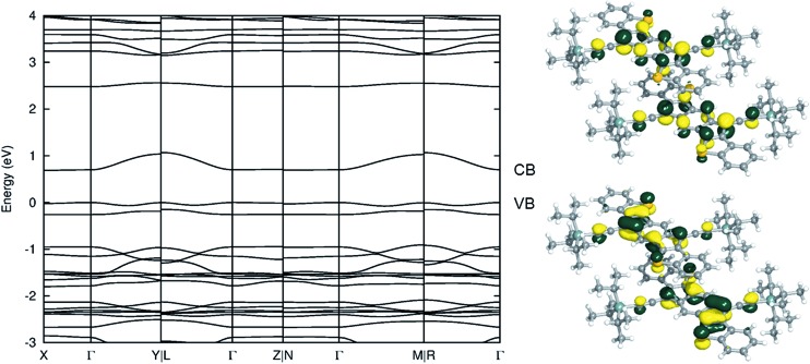
As an initial evaluation, the intermolecular electronic couplings (t) and electronic band structure of 6f reveal the potential for hole and/or electron transport (the band structures for 6d and 7d are in the ESI†). Using the fragment orbital approach26 at the B3LYP/cc-pVDZ level of theory, the HOMO:HOMO electronic coupling (for hole transport) of the π-stacked dimer is found to be 50 meV, while the LUMO:LUMO electronic coupling (for electron transport) is twice as large at 100 meV. These electronic couplings are on par with those of other high performing organic semiconductor materials. Examination of the electronic band structure along various crystallographic directions of the triclinic (TRI1a) lattice (Fig. 10), using the experimental unit cell and atomic coordinates, reveals that the valence band dispersion is 78 meV, while the conduction band dispersion is 383 meV; relaxation of the atomic coordinates leads to a decrease of the band gap, while the band dispersions remain unaffected (see the ESI† for further details). Note that the valence band maximum is at Γ, while the conduction band minimum is at X; therefore, the band gap is indirect, but only because the conduction band following Γ–X is slightly sloped downwards (the Γ–Γ band gap is marginally larger). Overall, the magnitudes of the electronic couplings (and band widths) suggest that 6f could possess reasonable hole and electron transport characteristics.
Fig. 10. (Left) Electronic band structure for 6f in the triclinic lattice (TRI1a). The valence band [VB] and conduction band [CB] are labeled for clarity. The origin of the energy axis is set at the top of VB. (Right) Pictorial representations of the 6f dimer HOMO (bottom) and LUMO (top).
Organic field effect transistors
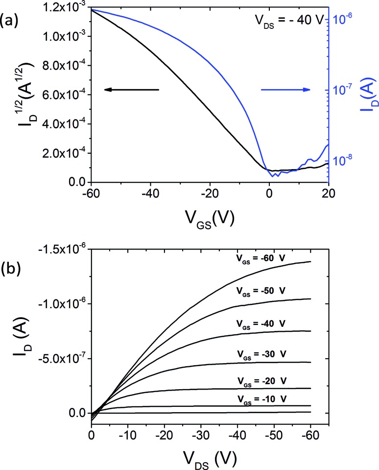
Top-gate, bottom-contact OFETs of 6f were fabricated on SiO2 substrates. Source and drain contacts were patterned by photolithography, with 5 nm of Ti and 40 nm Au deposited by e-beam evaporation. anti-IDBT 6f (1 wt% in room-temperature chlorobenzene) was then spin-coated onto this substrate. Undiluted Cytop fluoropolymer was used as a gate dielectric and spin-coated over the organic semiconductor. Our earlier work has shown that these processing conditions yield a dielectric thickness of 1400 nm.27 The OFETs were subsequently annealed at 110 °C for one hour in a vacuum oven to cross-link the dielectric layer and left to cool overnight. A 60 nm layer of Au was thermally evaporated through a shadow mask aligned over the conduction channel, and this served as the gate electrode. The resulting OFETs were measured under ambient conditions, and an example for current–voltage characteristics is included in Fig. 11. We calculated the field-effect mobility μ from the saturation regime of device operation, at an applied drain-to-source voltage of VDS = –40 V by standard procedures.28Fig. 11a shows the evolution of the drain current ID with the applied gate-to-source voltage VGS for this particular device of channel length L = 20 μm and channel width W = 35 μm. This device exhibits a hole mobility of μ = 0.44 cm2 V–1 s–1, and a threshold voltage of Vth = 1.33 V. Measurements over 10 devices yielded an average hole mobility of μavg = 0.14 cm2 V–1 s–1 ± 0.12 cm2 V–1 s–1. The low threshold voltage indicates a low density of trap states at the semiconductor–dielectric interface, which is to be expected for the transistors with Cytop gate dielectric.27Fig. 11b shows the transport characteristics for the same device. The transition from linear to saturation regime is clear for all investigated gate voltages. The non-linearity in the low-voltage region may originate from parasitic contact effects.29 These contact effects could be minimized by using surface treatments on the contacts which could also increase the measured mobility of devices; therefore, the values quoted for charge carrier mobility should be seen as a lower bound. The electrical measurements show hole-only charge transport. The lack of a measured electron transport likely originates from the fact that Au contacts were used, and while the ∼5 eV work function of Au aligns well with the estimated solid-state IP of 6f, the energy barrier to inject electrons is too large (see Table 1).30
Fig. 11. Transfer (a) and transport (b) characteristics of an OFET using anti-IDBT 6f. This device demonstrated a hole mobility of 0.44 cm2 V–1 s–1, and a threshold voltage of Vth = 1.33 V.
Conclusions
In summary, our analysis of the NICS-XY scans and ACID plots of IDBTs 6′ and 7′ indicate a strong antiaromatic ring current in the central s-indacene core of these molecules, and that IDBTs 6 and 7 are best thought as phenyl-substituted s-indacene derivatives with thioether linkages planarizing the appended phenyl groups to the indacene core. We have improved the synthesis of dione precursors 10 and 11 to yield multigram quantities without the use of column chromatography and demonstrated that up to 500 mg (6f) of the final IDBT can be produced in one batch. We have undertaken a detailed experimental and computational analysis of IDBT 6a–f and 7a–f and demonstrated that the optoelectronic, electrochemical characteristics and the solid-state morphology can be significantly altered by the choice of aryl/ethynyl substitution. Analysis of the intermolecular electronic couplings and electronic band structure of 6f indicated that it could perform well as the active element in an OFET device. Fabrication of a device with 6f produced the highest hole mobilities recorded to date using a fully conjugated indenofluorene derivative. Future work will focus on further exploration of the antiaromatic properties of IDBTs 6 and 7 as well as benzothiophene fusion as a means to control aromaticity/antiaromaticity in other IF related structures.
Supplementary Material
Acknowledgments
We thank the National Science Foundation (CHE-1301485) for support of the U Oregon research, as well as for support in the form of an instrumentation grant (CHE-1427987). The device studies at WFU were supported by the National Science Foundation under grant ECCS-1254757. C. R. thanks the University of Kentucky Vice President for Research for start-up funds, and Dr Gjergji Sini for fruitful discussions. K. U. was partly supported by the Osaka University Scholarship for Short-term Overseas Research Activities 2013. HRMS were obtained at the Mass Spectrometry Facilities and Services Core of the Environmental Health Sciences Center, Oregon State University, supported by grant #L30-CS00210, National Institute of Environmental Health Sciences, National Institutes of Health.
Footnotes
†Electronic supplementary information (ESI) available: Experimental details, spectroscopic data, computational details, device details and copies of 1H and 13C NMR spectra. CCDC 1451107–1451110. For ESI and crystallographic data in CIF or other electronic format see DOI: 10.1039/c6sc00950f
‡It should be noted that NICS-XY values and ACID plot CIV values for antiaromatic compounds are exaggerated and should be treated with some caution. The results presented in this paper should not be seen as a definitive value of antiaromaticity, but rather as a method for comparison between similar systems.
§In our hands, isolation of 7f proved to be highly problematic as we were unable to obtain more than 1–2 mg of moderately pure material. Further attempts at purification resulted in complete degradation of the material and multiple attempts were necessary to produce the data provided in this manuscript.
¶For a discussion on the differences between optically determined, electrochemically-determined and computationally determined HOMO/LUMO levels, energy gaps, and their terminology, please see: J.-L. Bredas, Mater. Horiz. 2014, 1, 17.
References
- Hückel E. Z. Phys. A: At. Nucl. 1931;70:204. [Google Scholar]
- Breslow R., Brown J., Gajewski J. J. J. Am. Chem. Soc. 1967;89:4383. [Google Scholar]
- (a) Allen A. D., Tidwell T. T. Chem. Rev. 2001;101:1333. doi: 10.1021/cr990316t. [DOI] [PubMed] [Google Scholar]; (b) Breslow R. Acc. Chem. Res. 1973;6:393. [Google Scholar]; (c) Breslow R. Chem. Rec. 2014;14:1174. doi: 10.1002/tcr.201402070. [DOI] [PubMed] [Google Scholar]; (d) Cyrañski M. K., Krygowski T. M., Katritzky A. R., Schleyer P. V. R. J. Org. Chem. 2002;67:1333. doi: 10.1021/jo016255s. [DOI] [PubMed] [Google Scholar]; (e) Krygowski T. M., Cyrañski M. K., Czarnocki Z., Häfelinger G., Katritzky A. R. Tetrahedron. 2000;56:1783. [Google Scholar]
- (a) Alkorta I., Rozas I., Elguero J. Tetrahedron. 2001;57:6043. [Google Scholar]; (b) Chen Z., Wannere C. S., Corminboeuf C., Puchta R., von Schleyer P. Chem. Rev. 2005;105:3842. doi: 10.1021/cr030088+. [DOI] [PubMed] [Google Scholar]; (c) Mills N. S. Pure Appl. Chem. 2012;84:1101. [Google Scholar]; (d) Mills N. S., Llagostera K. B. J. Org. Chem. 2007;72:9163. doi: 10.1021/jo7013609. [DOI] [PubMed] [Google Scholar]; (e) Nishinaga T., Ohmae T., Aita K., Takase M., Iyoda M., Arai T., Kunugi Y. Chem. Commun. 2013;49:5354. doi: 10.1039/c3cc41764f. [DOI] [PubMed] [Google Scholar]; (f) Nishinaga T., Ohmae T., Iyoda M. Symmetry. 2010;2:76. doi: 10.1021/ja908161r. [DOI] [PubMed] [Google Scholar]; (g) Rosenberg M., Dahlstrand C., Kilsa K., Ottosson H. Chem. Rev. 2014;114:5379. doi: 10.1021/cr300471v. [DOI] [PubMed] [Google Scholar]; (h) Soriano Jartín R., Ligabue A., Soncini A., Lazzeretti P. J. Phys. Chem. A. 2002;106:11806. [Google Scholar]; (i) Wiberg K. B. Chem. Rev. 2001;101:1317. doi: 10.1021/cr990367q. [DOI] [PubMed] [Google Scholar]; (j) Wu W., Su P., Shaik S., Hiberty P. C. Chem. Rev. 2011;111:7557. doi: 10.1021/cr100228r. [DOI] [PubMed] [Google Scholar]; (k) Sugawara S., Hirata Y., Kojima S., Yamamoto Y., Miyazaki E., Takimiya K., Matsukawa S., Hashizume D., Mack J., Kobayashi N., Fu Z., Kadish K. M., Sung Y. M., Kim K. S., Kim D. Chem.–Eur. J. 2012;18:3566. doi: 10.1002/chem.201101846. [DOI] [PubMed] [Google Scholar]; (l) Sung Y. M., Oh J., Kim W., Mori H., Osuka A., Kim D. J. Am. Chem. Soc. 2015;137:11856. doi: 10.1021/jacs.5b04047. [DOI] [PubMed] [Google Scholar]
- (a) Bally T., Chai S., Neuenschwander M., Zhu Z. J. Am. Chem. Soc. 1997;119:1869. [Google Scholar]; (b) Cao J., London G., Dumele O., von Wantoch Rekowski M., Trapp N., Ruhlmann L., Boudon C., Stanger A., Diederich F. J. Am. Chem. Soc. 2015;137:7178. doi: 10.1021/jacs.5b03074. [DOI] [PubMed] [Google Scholar]; (c) Hertwig R. H., Holthausen M. C., Koch W., Maksi Z. B. Angew. Chem., Int. Ed. Engl. 1994;33:1192. [Google Scholar]; (d) Nendel M., Goldfuss B., Houk K. N., Hafner K. J. Mol. Struct.: THEOCHEM. 1999;461–462:23. [Google Scholar]
- (a) Breslow R., Foss Jr F. W. J. Phys.: Condens. Matter. 2008;20:374104. [Google Scholar]; (b) Breslow R., Schneebeli S. T. Tetrahedron. 2011;67:10171. [Google Scholar]; (c) Mei J., Diao Y., Appleton A. L., Fang L., Bao Z. J. Am. Chem. Soc. 2013;135:6724. doi: 10.1021/ja400881n. [DOI] [PubMed] [Google Scholar]
- (a) Organic Light Emitting Devices: Synthesis, Properties and Applications, ed. K. Mullen and U. Scherf, Wiley-VCH, Weinheim, 2006.; (b) Carbon-rich Compounds: From Molecules to Materials, ed. M. M. Haley and R. R. Tykwinski, Wiley-VCH, Weinheim, 2006.; (c) Functional Organic Materials, ed. T. J. J. Müller and U. H. F. Bunz, Wiley-VCH, Weinheim, 2007.; (d) Anthony J. E. Chem. Rev. 2006;106:5028. doi: 10.1021/cr050966z. [DOI] [PubMed] [Google Scholar]; (e) Anthony J. E. Nat. Mater. 2014;13:773. doi: 10.1038/nmat4034. [DOI] [PubMed] [Google Scholar]; (f) Baumeier B., Kirkpatrick J., Andrienko D. Phys. Chem. Chem. Phys. 2010;12:11103. doi: 10.1039/c002337j. [DOI] [PubMed] [Google Scholar]; (g) Bredas J. L., Calbert J. P., da Silva Filho D. A., Cornil J. Proc. Natl. Acad. Sci. U. S. A. 2002;99:5804. doi: 10.1073/pnas.092143399. [DOI] [PMC free article] [PubMed] [Google Scholar]; (h) Dong H., Fu X., Liu J., Wang Z., Hu W. Adv. Mater. 2013;25:6158. doi: 10.1002/adma.201302514. [DOI] [PubMed] [Google Scholar]; (i) Dong H., Wang C., Hu W. Chem. Commun. 2010;46:5211. doi: 10.1039/c0cc00947d. [DOI] [PubMed] [Google Scholar]; (j) Miao Q. Synlett. 2012:326. [Google Scholar]; (k) Wu J., Pisula W., Muellen K. Chem. Rev. 2007;107:718. doi: 10.1021/cr068010r. [DOI] [PubMed] [Google Scholar]
- (a) de Mello J., Anthony J., Lee S. ChemPhysChem. 2015;16:1099. doi: 10.1002/cphc.201500229. [DOI] [PubMed] [Google Scholar]; (b) Giri G., Verploegen E., Mannsfeld S. C. B., Atahan-Evrenk S., Kim D. H., Lee S. Y., Becerril H. A., Aspuru-Guzik A., Toney M. F., Bao Z. Nature. 2011;480:504. doi: 10.1038/nature10683. [DOI] [PubMed] [Google Scholar]; (c) Hong L., Brédas J.-L., Lennartz C. J. Chem. Phys. 2007;126:164704. doi: 10.1063/1.2727480. [DOI] [PubMed] [Google Scholar]; (d) Li Y., Wu Y., Liu P., Prostran Z., Gardner S., Ong B. S. Chem. Mater. 2007;19:418. [Google Scholar]; (e) Maliakal A., Raghavachari K., Katz H., Chandross E., Siegrist T. Chem. Mater. 2004;16:4980. [Google Scholar]; (f) Northrop B. H., Houk K. N., Maliakal A. Photochem. Photobiol. Sci. 2008;7:1463. doi: 10.1039/b813752h. [DOI] [PubMed] [Google Scholar]; (g) Ono K., Totani H., Hiei T., Yoshino A., Saito K., Eguchi K., Tomura M., Nishida J.-i., Yamashita Y. Tetrahedron. 2007;63:9699. [Google Scholar]; (h) Risko C., Bredas J. L. Top. Curr. Chem. 2014;352:1. doi: 10.1007/128_2013_459. [DOI] [PubMed] [Google Scholar]; (i) Sanders S. N., Kumarasamy E., Pun A. B., Trinh M. T., Choi B., Xia J., Taffet E. J., Low J. Z., Miller J. R., Roy X., Zhu X. Y., Steigerwald M. L., Sfeir M. Y., Campos L. M. J. Am. Chem. Soc. 2015;137:8965. doi: 10.1021/jacs.5b04986. [DOI] [PubMed] [Google Scholar]; (j) Shepherd W. E. B., Grollman R., Robertson A., Paudel K., Hallani R., Loth M. A., Anthony J. E., Ostroverkhova O. Chem. Phys. Lett. 2015;629:29. [Google Scholar]; (k) Sheraw C. D., Jackson T. N., Eaton D. L., Anthony J. E. Adv. Mater. 2003;15:2009. [Google Scholar]; (l) Sherman J. B., Purushothaman B., Parkin S. R., Kim C., Collins S., Anthony J., Nguyen T.-Q., Chabinyc M. L. J. Mater. Chem. A. 2015;3:9989. [Google Scholar]; (m) Ward J. W., Li R., Obaid A., Payne M. M., Smilgies D.-M., Anthony J. E., Amassian A., Jurchescu O. D. Adv. Funct. Mater. 2014;24:5052. [Google Scholar]; (n) Yu L., Li X., Pavlica E., Koch F. P. V., Portale G., da Silva I., Loth M. A., Anthony J. E., Smith P., Bratina G., Kjellander B. K. C., Bastiaansen C. W. M., Broer D. J., Gelinck G. H., Stingelin N. Chem. Mater. 2013;25:1823. [Google Scholar]; (o) Goetz K. P., Li Z., Ward J. W., Bougher C., Rivnay J., Smith J., Conrad B. R., Parkin S. R., Anthopoulos T. D., Salleo A., Anthony J. E., Jurchescu O. D. Adv. Mater. 2011;23:3698. doi: 10.1002/adma.201101619. [DOI] [PubMed] [Google Scholar]; (p) Mei Y., Loth M. A., Payne M., Zhang W., Smith J., Day C. S., Parkin S. R., Heeney M., McCulloch I., Anthopoulos T. D., Anthony J. E., Jurchescu O. D. Adv. Mater. 2013;25:4352. doi: 10.1002/adma.201205371. [DOI] [PubMed] [Google Scholar]; (q) Purushothaman B., Parkin S. R., Kendrick M. J., David D., Ward J. W., Yu L., Stingelin N., Jurchescu O. D., Ostroverkhova O., Anthony J. E. Chem. Commun. 2012;48:8261. doi: 10.1039/c2cc33919f. [DOI] [PubMed] [Google Scholar]
- (a) Fullerenes: Principles and Applications, ed. F. Langa and J.-F. Nierengarten, Royal Society of Chemistry, Cambridge, 2011.; (b) Anthony J. E. Angew. Chem., Int. Ed. 2008;47:452. doi: 10.1002/anie.200604045. [DOI] [PubMed] [Google Scholar]; (c) Anthony J. E., Brooks J. S., Eaton D. L., Parkin S. R. J. Am. Chem. Soc. 2001;123:9482. doi: 10.1021/ja0162459. [DOI] [PubMed] [Google Scholar]; (d) Anthony J. E., Facchetti A., Heeney M., Marder S. R., Zhan X. Adv. Mater. 2010;22:3876. doi: 10.1002/adma.200903628. [DOI] [PubMed] [Google Scholar]; (e) Clar E., Polycyclic Hydrocarbons, Academic, London, 1964. [Google Scholar]; (f) Harvey R. G., Polycyclic Aromatic Hydrocarbons, Wiley-VCH, New York, 1997. [Google Scholar]
- (a) Breslow R. Chem. Eng. News. 1965;43:90. [Google Scholar]; (b) Brunetti F. G., Gong X., Tong M., Heeger A. J., Wudl F. Angew. Chem., Int. Ed. 2010;49:532. doi: 10.1002/anie.200905117. [DOI] [PubMed] [Google Scholar]; (c) Hopf H. Angew. Chem., Int. Ed. 2013;52:12224. doi: 10.1002/anie.201307162. [DOI] [PubMed] [Google Scholar]; (d) Nishinaga T., Nodera N., Miyata Y., Komatsu K. J. Org. Chem. 2002;67:6091. doi: 10.1021/jo025786t. [DOI] [PubMed] [Google Scholar]; (e) Plunkett K. N. Synlett. 2013:898. [Google Scholar]; (f) Scott L. T. Polycyclic Aromat. Compd. 2010;30:247. [Google Scholar]; (g) Shimizu A., Nobusue S., Miyoshi H., Tobe Y. Pure Appl. Chem. 2014;86:517. [Google Scholar]; (h) Steffen L. K., Plummer B. F., Braley T. L., Reese W. G., Zych K., Van Dyke G., Gill M. J. Phys. Org. Chem. 1997;10:623. [Google Scholar]; (i) Tobe Y. Chem. Rec. 2015;15:86. doi: 10.1002/tcr.201402077. [DOI] [PubMed] [Google Scholar]
- (a) Bendikov M., Wudl F., Perepichka D. F. Chem. Rev. 2004;104:4891. doi: 10.1021/cr030666m. [DOI] [PubMed] [Google Scholar]; (b) Levi Z. U., Tilley T. D. J. Am. Chem. Soc. 2009;131:2796. doi: 10.1021/ja809930f. [DOI] [PubMed] [Google Scholar]; (c) Stevens L. A., Goetz K. P., Fonari A., Shu Y., Williamson R. M., Brédas J.-L., Coropceanu V., Jurchescu O. D., Collis G. E. Chem. Mater. 2015;27:112. [Google Scholar]; (d) Sun Z., Huang K. W., Wu J. J. Am. Chem. Soc. 2011;133:11896. doi: 10.1021/ja204501m. [DOI] [PubMed] [Google Scholar]; (e) Usta H., Facchetti A., Marks T. J. J. Am. Chem. Soc. 2008;130:8580. doi: 10.1021/ja802266u. [DOI] [PubMed] [Google Scholar]; (f) Usta H., Risko C., Wang Z., Huang H., Deliomeroglu M. K., Zhukhovitskiy A., Facchetti A., Marks T. J. J. Am. Chem. Soc. 2009;131:5586. doi: 10.1021/ja809555c. [DOI] [PubMed] [Google Scholar]
- Mahendran A., Gopinath P., Breslow R. Tetrahedron Lett. 2015;56:4833. [Google Scholar]
- (a) Chase D. T., Fix A. G., Kang S. J., Rose B. D., Weber C. D., Zhong Y., Zakharov L. N., Lonergan M. C., Nuckolls C., Haley M. M. J. Am. Chem. Soc. 2012;134:10349. doi: 10.1021/ja303402p. [DOI] [PubMed] [Google Scholar]; (b) Nishida J., Deno H., Ichimura S., Nakagawa T., Yamashita Y. J. Mater. Chem. 2012;22:4483. [Google Scholar]; (c) Nishida J., Tsukaguchi S., Yamashita Y. Chem.–Eur. J. 2012;18:8964. doi: 10.1002/chem.201200591. [DOI] [PubMed] [Google Scholar]
- (a) Fix A. G., Chase D. T., Haley M. M. Top. Curr. Chem. 2014;349:159. doi: 10.1007/128_2012_376. [DOI] [PubMed] [Google Scholar]; (b) Marshall J. L. and Haley M. M., in Organic Redox Systems: Synthesis, Properties and Applications, ed. T. Nishinaga, Wiley, New York, 2016, ch. 10, p. 311. [Google Scholar]
- (a) Frantz D. K., Walish J. J., Swager T. M. Org. Lett. 2013;15:4782. doi: 10.1021/ol402153w. [DOI] [PMC free article] [PubMed] [Google Scholar]; (b) Fu X., Zhao D. Org. Lett. 2015;17:5694. doi: 10.1021/acs.orglett.5b03000. [DOI] [PubMed] [Google Scholar]; (c) Fukuda K., Nagami T., Fujiyoshi J.-y., Nakano M. J. Phys. Chem. A. 2015;119:10620. doi: 10.1021/acs.jpca.5b08520. [DOI] [PubMed] [Google Scholar]; (d) Martinez I., Zarate X., Schott E., Morales-Verdejo C., Castillo F., Manríquez J. M., Chávez I. Chem. Phys. Lett. 2015;636:31. [Google Scholar]; (e) Miyoshi H., Nobusue S., Shimizu A., Hisaki I., Miyata M., Tobe Y. Chem. Sci. 2014;5:163. [Google Scholar]; (f) Rao M. R., Desmecht A., Perepichka D. F. Chem.–Eur. J. 2015;21:6193. doi: 10.1002/chem.201406646. [DOI] [PubMed] [Google Scholar]; (g) Romain M., Chevrier M., Bebiche S., Mohammed-Brahim T., Rault-Berthelot J., Jacques E., Poriel C. J. Mater. Chem. C. 2015;3:5742. [Google Scholar]; (h) Shimizu A., Kishi R., Nakano M., Shiomi D., Sato K., Takui T., Hisaki I., Miyata M., Tobe Y. Angew. Chem., Int. Ed. 2013;52:6076. doi: 10.1002/anie.201302091. [DOI] [PubMed] [Google Scholar]; (i) Shimizu A., Tobe Y. Angew. Chem., Int. Ed. 2011;50:6906. doi: 10.1002/anie.201101950. [DOI] [PubMed] [Google Scholar]; (j) Takeda T., Inukai K., Tahara K., Tobe Y. J. Org. Chem. 2011;76:9116. doi: 10.1021/jo2014593. [DOI] [PubMed] [Google Scholar]; (k) Zhang X.-Y., Huang J.-D., Yu J.-J., Li P., Zhang W.-P., Frauenheim T. Phys. Chem. Chem. Phys. 2015;17:25463. doi: 10.1039/c5cp01868d. [DOI] [PubMed] [Google Scholar]
- (a) Chase D. T., Fix A. G., Rose B. D., Weber C. D., Nobusue S., Stockwell C. E., Zakharov L. N., Lonergan M. C., Haley M. M. Angew. Chem., Int. Ed. 2011;50:11103. doi: 10.1002/anie.201104797. [DOI] [PubMed] [Google Scholar]; (b) Chase D. T., Rose B. D., McClintock S. P., Zakharov L. N., Haley M. M. Angew. Chem., Int. Ed. 2011;50:1127. doi: 10.1002/anie.201006312. [DOI] [PubMed] [Google Scholar]; (c) Fix A. G., Deal P. E., Vonnegut C. L., Rose B. D., Zakharov L. N., Haley M. M. Org. Lett. 2013;15:1362. doi: 10.1021/ol400318z. [DOI] [PubMed] [Google Scholar]; (d) Frederickson C. K., Haley M. M. J. Org. Chem. 2014;79:11241. doi: 10.1021/jo502009p. [DOI] [PubMed] [Google Scholar]; (e) Haley M. M. Chem. Rec. 2015;15:1140. doi: 10.1002/tcr.201510004. [DOI] [PubMed] [Google Scholar]; (f) Marshall J. L., Rudebusch G. E., Vonnegut C. L., Zakharov L. N., Haley M. M. Tetrahedron Lett. 2015;56:3235. [Google Scholar]; (g) Rose B. D., Chase D. T., Weber C. D., Zakharov L. N., Lonergan M. C., Haley M. M. Org. Lett. 2011;13:2106. doi: 10.1021/ol200525g. [DOI] [PubMed] [Google Scholar]; (h) Rose B. D., Maria P. J. S., Fix A. G., Vonnegut C. L., Zakharov L. N., Parkin S. R., Haley M. M. Beilstein J. Org. Chem. 2014;10:2122. doi: 10.3762/bjoc.10.219. [DOI] [PMC free article] [PubMed] [Google Scholar]; (i) Rose B. D., Sumner N. J., Filatov A. S., Peters S. J., Zakharov L. N., Petrukhina M. A., Haley M. M. J. Am. Chem. Soc. 2014;136:9181. doi: 10.1021/ja503870z. [DOI] [PubMed] [Google Scholar]; (j) Rose B. D., Vonnegut C. L., Zakharov L. N., Haley M. M. Org. Lett. 2012;14:2426. doi: 10.1021/ol300942z. [DOI] [PubMed] [Google Scholar]; (k) Rudebusch G. E., Fix A. G., Henthorn H. A., Vonnegut C. L., Zakharov L. N., Haley M. M. Chem. Sci. 2014;5:3627. [Google Scholar]; (l) Young B. S., Chase D. T., Marshall J. L., Vonnegut C. L., Zakharov L. N., Haley M. M. Chem. Sci. 2014;5:1008. doi: 10.1039/C3SC53181C. [DOI] [PMC free article] [PubMed] [Google Scholar]; (m) Marshall J. L., O'Neal N. J., Zakharov L. N., Haley M. M. J. Org. Chem. 2016;81:3674. doi: 10.1021/acs.joc.6b00340. [DOI] [PubMed] [Google Scholar]; (n) Rudebusch G. E., Zafra J. L., Jorner K., Fukuda K., Marshall J. L., Arrechea-Marcos I., Espejo G. L., Ponce-Ortiz R., Gomez-Garcia C. J., Zakharov L. N., Nakano M., Ottosson H., Casado J., Haley M. M., Nat. Chem., 2016, 810.1038/nchem.2518 , , in press . [DOI] [PubMed] [Google Scholar]
- Gershoni-Poranne R., Stanger A. Chem.–Eur. J. 2014;20:5673. doi: 10.1002/chem.201304307. [DOI] [PubMed] [Google Scholar]
- (a) Rahalkar A. and Stanger A., http://schulich.technion.ac.il/Amnon_Stanger.htm.; (b) Stanger A. J. Org. Chem. 2006;71:883. doi: 10.1021/jo051746o. [DOI] [PubMed] [Google Scholar]; (c) Stanger A. J. Org. Chem. 2010;75:2281. doi: 10.1021/jo1000753. [DOI] [PubMed] [Google Scholar]; (d) Wolinski K., Hinton J. F., Pulay P. J. Am. Chem. Soc. 1990;112:8251. [Google Scholar]
- (a) Geuenich D., Hess K., Köhler F., Herges R. Chem. Rev. 2005;105:3758. doi: 10.1021/cr0300901. [DOI] [PubMed] [Google Scholar]; (b) Herges R., Geuenich D. J. Phys. Chem. A. 2001;105:3214. [Google Scholar]
- Herges R., in The Chemical Bond: Chemical Bonding Across the Periodic Table, ed. G. Frenking and S. Shaik, Wiley-VCH, Weinheim, 2014, ch. 13, p. 383. [Google Scholar]
- Tao J., Perdew J. P., Staroverov V. N., Scuseria G. E. Phys. Rev. Lett. 2003;91:146401. doi: 10.1103/PhysRevLett.91.146401. [DOI] [PubMed] [Google Scholar]
- van Wüllen C., Kutzelnigg W. Chem. Phys. Lett. 1993;205:563. [Google Scholar]
- Rose B. D., Shoer L. E., Wasielewski M. R., Haley M. M. Chem. Phys. Lett. 2014;616–617:137. [Google Scholar]
- (a) Coates G. W., Dunn A. R., Henling L. M., Dougherty D. A., Grubbs R. H. Angew. Chem., Int. Ed. Engl. 1997;36:248. [Google Scholar]; (b) Dai C., Nguyen P., Marder T. B., Marder T. B., Scott A. J., Clegg W., Viney C., Viney C. Chem. Commun. 1999:2493. [Google Scholar]; (c) Naae D. G. Acta Crystallogr., Sect. B: Struct. Crystallogr. Cryst. Chem. 1979;35:2765. [Google Scholar]
- (a) Gopalakrishna T. Y., Reddy J. S., Anand V. G. Angew. Chem., Int. Ed. 2013;52:1763. doi: 10.1002/anie.201207987. [DOI] [PubMed] [Google Scholar]; (b) Xia Y., Viel S., Wang Y., Ziarelli F., Laurini E., Posocco P., Fermeglia M., Qu F., Pricl S., Peng L. Chem. Commun. 2012;48:4284. doi: 10.1039/c2cc18147a. [DOI] [PubMed] [Google Scholar]
- Valeev E. F., Coropceanu V., da Silva Filho D. A., Salman S., Brédas J.-L. J. Am. Chem. Soc. 2006;128:9882. doi: 10.1021/ja061827h. [DOI] [PubMed] [Google Scholar]
- Diemer P. J., Lamport Z. A., Mei Y., Ward J. W., Goetz K. P., Li W., Payne M. M., Guthold M., Anthony J. E., Jurchescu O. D. Appl. Phys. Lett. 2015;107:103303. [Google Scholar]
- Klauk H. Chem. Soc. Rev. 2010;39:2643. doi: 10.1039/b909902f. [DOI] [PubMed] [Google Scholar]
- Gundlach D. J., Zhou L., Nichols J. A., Jackson T. N., Necliudov P. V., Shur M. S. J. Appl. Phys. 2006;100:024509. [Google Scholar]
- Ward J. W., Loth M. A., Kline R. J., Coll M., Ocal C., Anthony J. E., Jurchescu O. D. J. Mater. Chem. 2012;22:19047. [Google Scholar]
Associated Data
This section collects any data citations, data availability statements, or supplementary materials included in this article.


