Abstract
We present an adaptive optics parallel confocal scanning ophthalmoscope (AOPCSO) using a digital micromirror device (DMD). The imaging light is modulated to be a line of point sources by the DMD, illuminating the retina simultaneously. By using a high speed line camera to acquire the image and using adaptive optics to compensate ocular wave aberration, the AOPCSO can image the living human eye with cellular level resolution at the frame rate of 100 Hz. AOPCSO has been demonstrated with improved spatial resolution in imaging of the living human retina compared with adaptive optics line scan ophthalmoscopy.
Adaptive optics (AO) confocal retinal imaging, as represented by AO scanning laser ophthalmoscopy (AOSLO) [1, 2], is particularly attractive for imaging of the en face microstructure of the living retina. An important ability of this imaging modality is that it can control depth of field and reject out-of-focus scattering light thereby producing retinal images with enhanced contrast, compared to non-confocal imaging systems. This ability originates from the confocal imaging nature but is severely diminished by the wave aberration induced by the living human eye’s optical imperfection in non-AO imaging. AO compensates the ocular optical aberrations, enabling diffraction-limited imaging thereby allowing for fully exploiting the benefits of confocal imaging [1]. Moreover, by use of low coherent light, AOSLO renders the retinal structure with reduced light interference artifacts [3].
Two AO confocal imaging regimes have been reported. The first one is the AOSLO in which confocal imaging is achieved by scanning the retina with a ‘flying light spot’ and detecting the back-scattered light through a confocal pinhole that rejects the out-of-focus scattering [1]. This system is confocal but its frame rate is limited by the speed of the fast scanner which typically is a resonant scanner operating with a frequency of 8 – 16 KHz. For an image consisting of 512 lines, the frame rate of the AOSLO is 15 – 30 frames per second (FPS). This speed is slower than the involuntary movement (during fixation) of the human eye, which includes different movements (drift, tremor, and micro saccade) of different amplitudes and frequency (up to 100 Hz or even more) [4]. This constant retinal motion results in artifacts between frames and within a single frame [5, 6]. Quantitative study indicates that image distortion caused by involuntary eye motion in AOSLO can significantly affect the accuracy and repeatability of cone structure measurement even after image registration [6]. The other AO confocal imaging regime is line scanning ophthalmoscopy (AOLSO) in which a light line (typically formed by a cylindrical lens) is projected onto the retina [7]. Confocal imaging is achieved by use of a line camera which also acts as a confocal slit to acquire the image formed by the back-scattered light. This method has the potential to increase frame rate; but the confocality is only realized in one direction that is orthogonal to the light line.
High resolution and high speed retinal imaging can further facilitate basic research on vision science and clinical research on retinal pathophysiology. We present a high resolution AO parallel confocal scanning ophthalmoscope (AOPCSO), which employs a digital micromirror device (DMD) to generate a line of point sources thereby achieving high speed confocal retinal imaging.
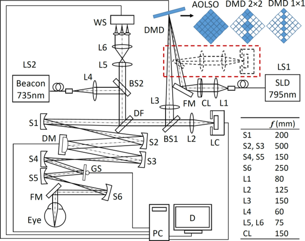
As illustrated in Fig. 1, the AOPCSO is comprised of four components: DMD line point sources generation, scanning optics, AO, and image acquisition. The imaging system employs a superluminescent diode (SLD) (Broadlighter S795-HP, Superlum Ltd., Russia) with a central wavelength at 795 nm and a spectral bandwidth of 15 nm. Light emitting from the SLD is first collimated and then focused by a cylindrical lens (CL) to form a light line on the DMD (Texas Instruments, DLP® 0.55 XGA Series 450 DMD, Dallas, US), which modulates the line illumination intensity to create a line of point sources. The width of the light line generated by the cylindrical lens is 27 µm. The modulated beam is collimated by lens L3 and fed into the scanning optics by a beam splitter BS1 (reflecting 20% of the light). Then the light is relayed to the deformable mirror (DM), the galvanometric scanner (GS), and finally the eye by the telescopes formed by a series of spherical mirrors (S1–S6), generating a 2D scanning pattern on the retina. Back scattered light from the retina following the ingoing path transmits (80% of the light) through the BS1 into the image acquisition arm. The AO consists of a beacon light (SuperK, NKT Photonics AS, Denmark) for wavefront sensing (λ=735 nm). The ocular wave aberration is measured by a custom Shack-Hartmann wavefront sensor (WS) and corrected by a high speed DM (Hi-Speed DM97-15, ALPAO SAS, France). The WS measures the wave aberration by 193 sampling points over a pupil of 6.75 mm (diameter). The DM has 97 actuators whose stroke can be up to 30 µm. The AO closed loop frequency is 50 Hz. In most eyes, the root mean square of the wave aberration can be compensated to be as low as 0.05 µm, less than 1/14 of the wavelength of the light for wavefront sensing. The image acquisition module involves a collecting lens L2 and a high speed line camera (spL2048-140km, Basler Co., Germany).
Fig. 1.
The AOPCSO system. SLD: superluminescent diode. DMD: digital micromirror device. LS1, LS2: Light sources. CL: Cylindrical lens. DF: Dichroic filter. L1–L6: Lenses. BS1, BS2: Beam splitter. S1–S5: Spherical mirrors. GS: Galvanometric scanner. FM: Flat mirrors. WS: Wavefront sensor. DM: Deformable mirror. LC: Line camera. PC: Computer. D: Display. Dash lines indicate the configuration in which the DMD is placed in both illumination and imaging paths. Top right shows 3 configurations of the DMD discussed in this letter. The “on” and “off” states of the micromirrors are represented by solid and hollow squares, respectively. The DMD is rotated by 45°.
The DMD has been considered to have a great potential for parallel confocal microscopy [8] and was recently employed for parallel confocal retinal imaging but not at the cellular level [9, 10]. The DMD used in this study has 1024 × 768 micromirrors which are in a square shape of 10.8 µm × 10.8 µm. Each micromirror has two states, “on” or “off”, corresponding to two angular positions (+12° and −12°) tilting along the diagonal of the element. The “on” or “off” state of each micromirror can be programmed individually to modulate the incidental light. In the AOPCSO, a series of micromirrors are programmed to be “on,” forming a line of microreflectors (each can consist of one or multiple micromirrors, as shown in Fig. 1) and modulate the light into a line of point sources, which were positioned to be conjugate to the retina and the camera. When all the micromirrors of the DMD are tuned ‘on,’ the imaging system is an AOLSO [7]. As a blazed grating, the DMD was positioned to ensure that the light incidental angle meeting the blazing condition, i.e., the reflecting beam of the ‘on’ state was co-aligned with the -1st order diffraction beam.
Ideally, to achieve parallel confocal imaging, the DMD should be placed in both light delivery and image acquisition paths, serving as a series of conjugate parallel light point sources and confocal pinholes [8]. This configuration was first implemented in this development, in which the back scattered light from the retina was relayed by the DMD to the camera (dashed line in Fig. 1.) However, this configuration could not produce images with sufficient signal to noise ratio (SNR) due to significant light loss on the DMD and insufficient power of the light source. Thus, the final imaging system had to adopt a suboptimal configuration; the DMD was placed in the light delivery path (solid lines in Fig. 1), modulating the illumination light only.
The size of an individual microreflector that modulates the light was chosen using the Nyquist sampling theorem, i.e., the optics for light delivery should ensure that the image size of individual microreflector on the retina is smaller than one-half the radius of the Airy disc of the eye, to ensure an adequate spatial sampling in the retinal plane. Meanwhile, the optical magnification in the image acquisition path (from the retina to the camera) should ensure that the digitization of the camera meets the sampling requirement. In our system, the magnification from DMD to human retina is 0.091. For a microreflector consisting of 1 micromirror, the diagonal length of the image of the microreflector on the retina is 1.39 µm (0.98 µm on one side). With a pupil diameter of 6.75 mm and imaging light wavelength of 795 nm, the radius of Airy disc of the human eye (Emsley reduced model eye) is 2.40 µm. Thus, this configuration meets the sampling requirement. For a microreflector consists of 2 × 2 micromirrors, the diagonal length of the image of the microreflector on the retina is 2.78 µm (1.96 µm on one side), which is slightly larger than the Airy disc radius. While this setting does not meet the sampling requirement, it can still improve imaging quality and ability of depth discrimination. This will be shown in the experiment.
The magnification from the retina to the line camera (LC) is 9.15, thus the Airy disk of the eye projects a spot of 21.96 µm (radius) on the LC, covering 2.19 pixels (10 µm × 10 µm/pixel). The field of view of the AOPCSO is 1.9° × 1.9° inside the eye and is digitized by 512 × 512 pixels. The highest frame rate of the camera can be 273 FPS with the present system configuration. However, to ensure the image can be rendered with SNR similar to that of the AOSLO image, the frame rate was set at 100 FPS with the line rate of the camera set at 51.2 KHz.
The power of the imaging light is 0.065 mW for the DMD 1 × 1 setting, 0.35 mW for DMD 2 × 2, and 0.80 mW for the AOLSO mode, corresponding to 0.04, 0.22, and 0.50 times of the ANSI max permissible exposures (MPE) under the condition of 1 hour continuous exposure [12, 13], respectively. The power of wavefront detection beacon is 0.025 mW, ~ 1/10 of the ANSI MPE under 1 hour continuous exposure. Accordingly, the composite MPE for multiple laser exposure (Σϕλ/MPEλ) are 0.14, 0.32, and 0.60, respectively, below the ANSI safety threshold [12, 13].
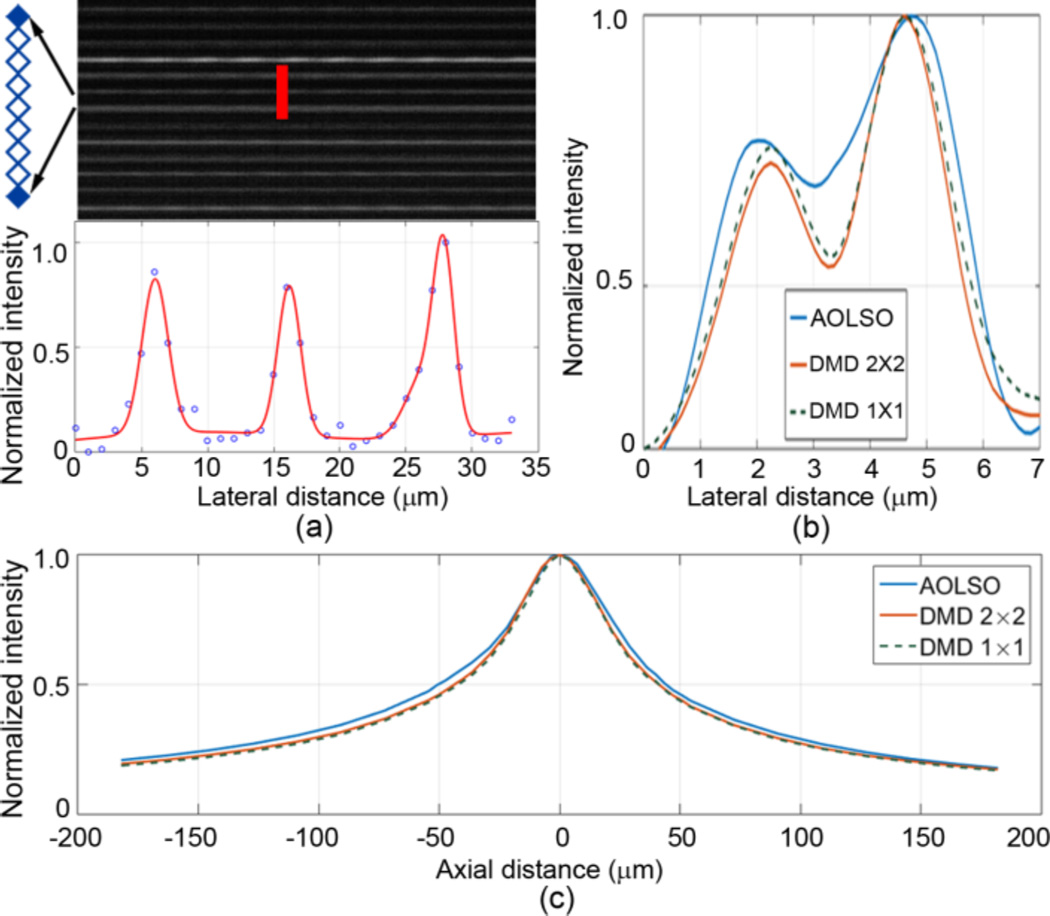
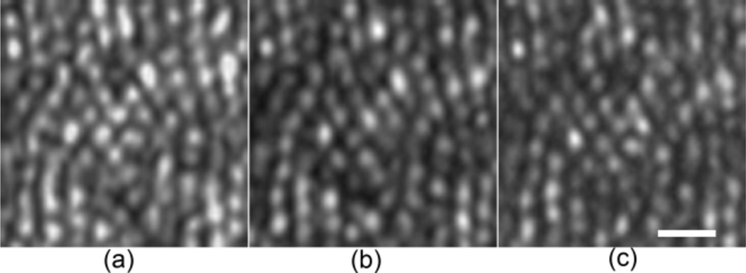
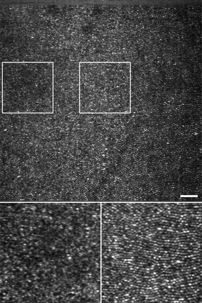
The imaging resolution was assessed in a model eye (Fig. 2) and in eyes of 3 human subjects (33 – 50 years old) with normal healthy retinas (Figs. 3 & 4) under 3 DMD settings. The model eye consists of an achromatic lens of 100 mm focal length and a diffuse reflector (#62-952, Edmund Optics Inc, Barrington, NJ) as the model retina. Lateral resolution improvement was demonstrated by enhanced separation of the intensity profiles of two arbitrary granules on the model retina with a distance of ~2.4 µm (Fig. 2(b)). Similar enhancement is also evident in the images acquired in the living human eye (Fig. 3). The DMD 1 × 1 setting did not show a greater advantage in improving the resolution than the DMD 2 × 2 setting but significantly reduced the imaging speed due to low imaging light. The DMD 2 × 2 configuration, although suboptimal, allows for a frame rate at 100 FPS with the image SNR and lateral resolution sufficient to render fine retinal structure, e.g., foveal cones (Fig. 4) and retinal capillaries near the avascular zone (Fig. 5).
Fig. 2.
AOPCSO spatial resolution assessed in a model eye. (a) Lateral resolution. To acquire the image (top) for assessing the later resolution, the DMD was set with the 1 × 1 mode, but only one element was turn ‘on’ on every 8 adjacent micromirrors. This configuration thus formed a series of separate true point sources. The average full width at half maximum (FWHM) of the normalized intensity profile of the bright lines formed by these point sources was used to estimate the lateral resolution, which is 2.40 µm. (b) Enhancement of lateral resolution is illustrated by the intensity profiles of 2 reflective spots (separated by 2.4 µm) on the retina of the model eye were imaged under 3 DMD configurations. (c) Axial resolution was measured following Romero- Borja et al [11]. The FWHM of the three configurations are 82.4 µm (DMD 1 × 1), 84.2 µm (DMD 2 × 2), and 95.1 µm (AOLSO).
Fig. 3.
Comparison of the lateral resolution of the AOPCSO with different DMD settings at 30 FPS. All images were acquired at 1.2° eccentricity nasally in the eye of a normal human subject of 50 years old age with a pupil size of 6.75 mm. The orientation of the line camera is along the vertical direction. (a) AOLSO. (b) DMD 2 × 2. (c) DMD 1 × 1. All images acquired with line exposure times adjusted to ensure a similar SNR. Each image is an average of registered 40 successive frames after Vogel et al [5]; but the retinal motion induced displacements in successive frames were estimated using a graphics processing unit accelerated fast Fourier transform algorithm. Brightness and contrast of all images have been adjusted with the same greyscale range. Scale bar is 10 µm.
Fig. 4.
AOPCSO human retinal image acquired at 100 FPS. Top panel is a single frame (Visualization 1). Signal frame SNR, as assessed by the ratio of the mean to the standard deviation of the pixel values, is 2.0. Bottom panels are enlarged view (single frame) of the retina indicated by the boxes on the top panel. The box on the left contains the foveal center, showing resolved foveal center cones, which may be better viewed in the registered image (Visualization 2). Scale bar is 50 µm.
Fig. 5.
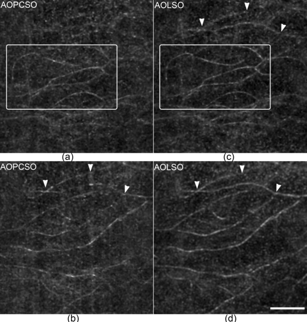
Comparison of the depth discrimination ability of AOLSO and AOPCSO. (a) and (b) are AOPCSO images of retinal capillaries taken at two retinal layers with a depth difference of approximately 73 µm. (a) is close to the photoreceptors and (b) is close to the nerve fiber layer. (c) and (d) are AOLSO images taken at the same layers corresponding to (a) and (b), respectively. The boxes in panels (a) and (c) contain retinal capillaries in the same layer revealed in the two imaging modes. The arrowheads indicate capillaries that are visualized in both AOLSO and AOPCSO images. All images were acquired at 100 FPS and 60 successive frames were registered to extract the retinal blood vessels. Scale bar represents 100 µm and applies for all images.
To assess the improvement of depth discrimination ability of the AOPCSO in human retina, we imaged the retinal capillaries in 2 retinal layers with an axial distance of ~73 µm (Fig. 5). The vessels were extracted using the standard deviation of a series of frames [14]. With the DMD 2 × 2 setting, the AOPCSO shows enhanced discrimination ability in comparison to the AOLSO; e.g., the capillaries indicated by the arrowheads appear in one layer of the AOPCSO image only (Fig. 5(b)) but appear in both layers of the AOLSO images (Figs. 5(c) & 5(d)).
The AOPCSO has been demonstrated with several technical advances. First, compared with the AOSLO, the AOPCSO possesses nearly comparable spatial resolution [3], but it can acquire retinal images at a much higher speed (100 FPS). This is very useful to minimize the imaging artifacts induced by the rapid and constant eye motion. Second, compared with the AOLSO [7], the AOPCSO not only achieves high speed but also effectively reduces the convolution or cross-talk along the imaging line thereby further enhancing spatial resolution. Moreover, the use of a line of microreflectors significantly reduced the light power on the retina compared to the line illumination of the AOLSO.
The DMD plays an important role in the AOPCSO for achieving parallel confocal imaging; but it is limited by low light efficiency due to the filling factor, diffraction efficiency, and reflectance of the micromirror array of the DMD. The DMD can only reflect 45%, 20%, and 8% of incidental light into the imaging path under the configurations of AOLSO, DMD 2 × 2, and DMD 1 × 1, respectively. Thus it was unable to serve as both the point sources and the parallel conjugate pinholes. Nonetheless, thanks to the fact that the confocal resolution is dominated by the illumination point spread function when the pinhole size is not sufficiently small, high quality retinal images were still obtained, even with another trade-off in which the microreflectors consist of 2 × 2 DMD micromirrors rather than the ideal 1 micromirror. As the main purpose of parallel confocal imaging is to improve image acquisition speed, we thus gained speed with slightly compromised resolution. In fact, the loss of resolution due to using the DMD 2 × 2 setting compared to the DMD 1 × 1 setting is negligible.
Using the FWHM of the point spread function as the measure, the lateral resolution of the AOPCSO can be estimated by 0.84rAirydisc/SR0.5, where rAirydisc is the radius of Airy disc, and SR is the Strehl ratio [15]. Assuming the SR is 0.8 (corresponding to a residual wave aberration of λ/14, i.e., a diffraction limited system), the theoretical lateral resolution of the AOPCSO would be 2.26 µm. The measured lateral resolution with the DMD 2 × 2 setting is 2.40 µm, very close to theoretical estimation.
We must acknowledge that the present system is still not a true confocal imaging mechanism and convolution or cross-talk along the imaging line still exists, though the strength is reduced. It is possible to further reduce or even eliminate the cross-talk completely by sweeping the DMD pixels, but this will be at the cost of reduced frame rate. In general, a high speed true confocal retinal imaging system may be achieved with a parallel illumination-detection regime. DMD is a useful but not the sole solution.
In conclusion, we have demonstrated a high speed confocal retinal imaging system. A high frame rate may reduce the spatial distortion of retinal imaging caused by involuntary fixational eye movements [6]. This instrument has the potential for investigating fast moving features like red and white blood cells through the retinal vasculature and recording rapid time-varying retina functional signals such as fluctuation in cone brightness, light induced bleaching, or light induced intrinsic signals [16–18].
Acknowledgments
Funding. National Institutes of Health (NIH) (EY021903, EY024378, P30 EY003039). National Science Foundation (NSF) (IIA-1539034); Institutional support from Research to Prevent Blindness and EyeSight Foundation of Alabama.
Extended References
- 1.Roorda A, Romero-Borja F, Donnelly Iii W, Queener H, Hebert T, Campbell M. Adaptive optics scanning laser ophthalmoscopy. Opt Express. 2002;10:405–412. doi: 10.1364/oe.10.000405. [DOI] [PubMed] [Google Scholar]
- 2.Roorda A, Duncan JL. Adaptive optics ophthalmoscopy. Annu Rev Vis Sci. 2015;1:19–50. doi: 10.1146/annurev-vision-082114-035357. [DOI] [PMC free article] [PubMed] [Google Scholar]
- 3.Zhang Y, Poonja S, Roorda A. MEMS-based adaptive optics scanning laser ophthalmoscopy. Opt Lett. 2006;31:1268–1270. doi: 10.1364/ol.31.001268. [DOI] [PubMed] [Google Scholar]
- 4.Martinez-Conde S, Macknik SL, Hubel DH. The role of fixational eye movements in visual perception. Nat Rev Neurosci. 2004;5:229–240. doi: 10.1038/nrn1348. [DOI] [PubMed] [Google Scholar]
- 5.Vogel CR, Arathorn DW, Roorda A, Parker A. Retinal motion estimation in adaptive optics scanning laser ophthalmoscopy. Opt Express. 2006;14:487–497. doi: 10.1364/opex.14.000487. [DOI] [PubMed] [Google Scholar]
- 6.Cooper RF, Sulai YN, Dubis AM, Chui TY, Rosen RB, Michaelides M, Dubra A, Carroll J. Effects of Intraframe Distortion on Measures of Cone Mosaic Geometry from Adaptive Optics Scanning Light Ophthalmoscopy. Transl Vis Sci Technol. 2016;5:10. doi: 10.1167/tvst.5.1.10. [DOI] [PMC free article] [PubMed] [Google Scholar]
- 7.Mujat M, Ferguson RD, Iftimia N, Hammer DX. Compact adaptive optics line scanning ophthalmoscope. Opt Express. 2009;17:10242–10258. doi: 10.1364/oe.17.010242. [DOI] [PMC free article] [PubMed] [Google Scholar]
- 8.Heintzmann R, Hanley QS, Arndt-Jovin D, Jovin TM. A dual path programmable array microscope (PAM): simultaneous acquisition of conjugate and non-conjugate images. J Microsc. 2001;204:119–135. doi: 10.1046/j.1365-2818.2001.00945.x. [DOI] [PubMed] [Google Scholar]
- 9.Muller MS, Green JJ, Baskaran K, Ingling AW, Clendenon JL, Gast TJ, Elsner AE. SPIE OPTO. International Society for Optics and Photonics; 2015. Non-mydriatic confocal retinal imaging using a digital light projector; p. 93760E-93760E-93710. [DOI] [PMC free article] [PubMed] [Google Scholar]
- 10.Vienola KV, Damodaran M, Braaf B, Vermeer KA, de Boer JF. Parallel line scanning ophthalmoscope for retinal imaging. Opt Lett. 2015;40:5335–5338. doi: 10.1364/OL.40.005335. [DOI] [PubMed] [Google Scholar]
- 11.Romero-Borja F, Venkateswaran K, Roorda A, Hebert T. Optical slicing of human retinal tissue in vivo with the adaptive optics scanning laser ophthalmoscope. Appl Opt. 2005;44:4032–4040. doi: 10.1364/ao.44.004032. [DOI] [PubMed] [Google Scholar]
- 12.Delori FC, Webb RH, Sliney DH I. American National Standards. Maximum permissible exposures for ocular safety (ANSI 2000), with emphasis on ophthalmic devices. J Opt Soc Am A Opt Image Sci Vis. 2007;24:1250–1265. doi: 10.1364/josaa.24.001250. [DOI] [PubMed] [Google Scholar]
- 13.Laser Institute of America. American National Standard for Safe Use of Lasers ANSI Z136.1-2014. 2014 [Google Scholar]
- 14.Chui TY, Zhong Z, Song H, Burns SA. Foveal avascular zone and its relationship to foveal pit shape. Optom Vis Sci. 2012;89:602–610. doi: 10.1097/OPX.0b013e3182504227. [DOI] [PMC free article] [PubMed] [Google Scholar]
- 15.Zhang Y, Roorda A. Evaluating the lateral resolution of the adaptive optics scanning laser ophthalmoscope. J Biomed Opt. 2006;11:014002. doi: 10.1117/1.2166434. [DOI] [PubMed] [Google Scholar]
- 16.Bedggood P, Metha A. Direct visualization and characterization of erythrocyte flow in human retinal capillaries. Biomed Opt Express. 2012;3:3264–3277. doi: 10.1364/BOE.3.003264. [DOI] [PMC free article] [PubMed] [Google Scholar]
- 17.Bedggood P, Metha A. Variability in bleach kinetics and amount of photopigment between individual foveal cones. Invest Ophthalmol Vis Sci. 2012;53:3673–3681. doi: 10.1167/iovs.11-8796. [DOI] [PubMed] [Google Scholar]
- 18.Bedggood P, Metha A. Optical imaging of human cone photoreceptors directly following the capture of light. PLoS One. 2013;8:e79251. doi: 10.1371/journal.pone.0079251. [DOI] [PMC free article] [PubMed] [Google Scholar]


