

Abstract
Cryo-electron microscopy (EM) and small angle X-ray scattering (SAXS) are two different data acquisition modalities often used to glean information about the structure of large biomolecular complexes in their native states. A SAXS experiment is generally considered fast and easy but unveils the structure at very low resolution, whereas a cryo-EM experiment needs more extensive preparation and postacquisition computation to yield a three-dimensional (3D) density map at higher resolution. In certain applications, we may need to verify whether the data acquired in the SAXS and cryo-EM experiments correspond to the same structure (e.g., before reconstructing the 3D density map in EM). In this article, a simple and fast method is proposed to verify the compatibility of the SAXS and EM experimental data. The method is based on averaging the two-dimensional correlation of EM images and the Abel transform of the SAXS data. Orientational preferences are known to exist in cryo-EM experiments, and we also consider these effects on our method. The results are verified on simulations of conformational states of large biomolecular complexes.
Keywords: : Abel transform, compatibility, correlation function, cryo-EM, preferred orientations, SAXS
1. Introduction
Biomolecular structure determination has been one of the main goals of structural biology for more than half a century. Due to the importance of the relationship between structure and function, many experimental methods have been developed to achieve this goal. Although X-ray crystallography and nuclear magnetic resonance (NMR) spectroscopy have been extensively used to construct three-dimensional (3D) structures of proteins (see www.rcsb.org/pdb/statistics/holdings.do for the statistics), there are some limitations associated with those methods, for example, both of them are suitable for only relatively small-sized molecules and complexes. Moreover, although X-ray crystallography can be used for somewhat larger structures rather than NMR, and has been the primary methodology for structure determination, the necessity of crystallization in this method is known as a daunting task, which imposes constraints on its use [see (Frank, 2002, p. 304) for more details]. Furthermore, since current interests have been shifted toward revealing the functions of large biomolecular complexes in cells and tissues, structural determination of large complexes has become more crucial than ever.
In contrast, cryo-electron microscopy (EM) (Frank 2002, 2006) and small angle X-ray scattering (SAXS) (Feigin et al., 1987; Svergun and Koch, 2003; Blanchet and Svergun, 2013; Svergun et al., 2013) are two popular—but very different—data acquisition modalities used to glean information about the structure of large biomolecular complexes in their native states. Both methods differ from crystallography in that no crystallization is needed (at the expense of lower resolution). The advantage is that finding appropriate crystallization conditions in many cases is either a very lengthy process or the process may capture the molecules in conditions that are not biologically relevant. A SAXS experiment is generally considered as fast and easy, but unveils the structure at very low resolution, whereas a cryo-EM experiment needs more preparation and postacquisition computation to yield a 3D density map at a higher resolution.
In SAXS experiments, the solution that contains biomolecular complexes of interest is exposed to X-ray beams, which leads to the scattering of X-ray photons. Unlike in X-ray crystallography where the macromolecules are regularly positioned and oriented, in SAXS the molecules can move and rotate randomly in solution. Hence, roughly speaking, the low resolution in SAXS can be attributed to the fact that the SAXS data are the spherical average of the scattering pattern of the complex under study. In cryo-EM, similar to standard tomography, we obtain numerous two-dimensional (2D) projections of a 3D complex. A specimen grid, with the molecules of interest in it, is prepared and exposed to high-energy electron beams to obtain millions of projected 2D images. However, in contrast to tomography, the projections are at random (unknown) directions; moreover, the projections are extremely noisy. As a result, the 3D volume reconstruction in cryo-EM involves complicated postprocessing and still the resolution is not very high.
Both SAXS and EM have been successfully used for the structural study of large biomolecular complexes. However, as explained earlier, they have their own disadvantages for the study of function–structure relationships. To better investigate the relationship between the function and the shape of a biomolecular complex, we may want to combine these two experimental data modalities (or fuse them). In such applications, we may first need to verify whether the data acquired in the SAXS and cryo-EM experiments correspond to the same structure (e.g., before reconstructing the 3D density map). In this article, we introduce a simple yet effective method that enables fast verification of the compatibility of data collected in SAXS and cryo-EM experiments.
Roughly speaking, we relate the planar correlations of EM images to the SAXS data. To the best of our knowledge, our work is the first attempt in establishing such a relationship and the derivations in Section 3.1 are new. The main benefit of our approach is that it enables the validation without the need for aligning and classification of the EM images or 3D reconstruction of the volume, which are complicated steps (Frank, 2006). The translation–invariance property of the correlation function is the key enabling factor to achieve this. The combination and validation of SAXS and EM data have appeared in the literature [e.g., (Vestergaard et al., 2005; Bron et al., 2008)]. However, such methods are mostly based on image processing techniques or visual verification. Correlation functions in the context of EM data have been used before (Schatz and Van Heel, 1990), but they became clear that for reconstruction of a 3D density map, the correlation function might not be adequate (Van Heel et al., 1992). Here, we prove that the correlation functions of EM images before averaging can be related to the SAXS data through the Abel transform.
The organization of this article is as follows: In Section 2, we review the mathematical modeling of the EM and SAXS data. In Section 3, the relationship between the SAXS and EM data is established and an algorithm for the validation is expressed. In Section 4, we perform some simulations to support our approach. In Section 5, we investigate the effect of preferred orientations in cryo-EM on our proposed method, and Section 6 concludes the article. This article builds upon and is expanded from prior work that was presented in the associated conference (Afsari et al., 2015). The focus of this article is to derive the basic mathematical methodology and to study its plausibility with simulated data, which contains both uniformly random and nonuniform (i.e., preferred) orientations. Applications with actual SAXS and EM data will appear later.
2. The EM and SAXS Data and Their Relationship
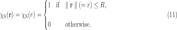
2.1. The cryo-EM data
The reader is referred to Frank (2006) for detailed physical and mathematical analyses of cryo-EM modeling and reconstruction. Here, we proceed with a very basic mathematical model. We model the 3D atomic density of a large biomolecular complex of interest as a uniform density map  , where
  and
and  (Frank, 2006). Although any uniform density function
  will work here, we specifically use
  as the characteristic function as in Dong and Chirikjian, 2014 and Dong et al., 2015, which is defined as
 |
where B denotes a biomolecular complex viewed as a solid body. With the characteristic function, a number of geometric quantities can be computed. For example, the volume of the complex body is computed as
 |
where  is the usual integration measure for
  .
.
In a cryo-EM experiment, a frozen sample containing the complex is imaged. Inside the sample, instances of the complex appear at random positions and orientations. This can be modeled by random rigid body motion  , where
  is the rotation component and
  is the translation component;
  and
and  denote, respectively, the Lie groups of rigid body motions and rotations in
  . A copy of the complex under random rotation and translation
  can be modeled as
 |
where  denotes the usual action of
  on
on  defined as
  . In the process of imaging, essentially every copy of the complex is imaged, and this is modeled by the projection along the z-axis in a global frame:
 |
Thus an EM image is the projection of a randomly translated and oriented copy of the complex. In reality, the EM images are highly noisy to the extent that signal-to-noise ratio (SNR) on the orders of  (i.e., the noise energy 100 times the signal energy) is quite common. Moreover, other effects such as the contrast transfer function of the microscope further deteriorate the images. Here, we ignore such effects. The standard reconstruction of the 3D volume
  from the 2D noisy projections
  is a complicated and lengthy process (Frank, 2006). We show in Section 3 that certain information that relates to the SAXS experiment can be obtained from the EM images with relatively simple operations and low computational load.
2.2. The SAXS data
Before progressing further, we have to mention that the SAXS and EM data are generated based on different physical principles and atomic properties. However, we expect that the information relevant to the geometry of a large complex would not be much affected by this difference. Thus we postulate that both SAXS and EM experiments yield information about the complex modeled by a uniform density  .
.
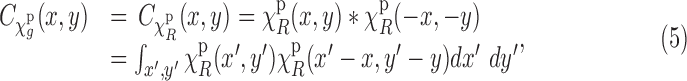
Having this assumption in mind, we formulate the mathematics of SAXS data. The data collected in a SAXS experiment can be related to the (spatial) correlation function of  [also known as the Patterson function (Svergun et al., 2013)], which is defined as
 |
where  denotes the convolution operation. Thus the correlation function
  is the convolution of
  with its reflection across the origin. The correlation function for a function defined on
  and
and  is defined similarly. In the frequency domain, we have
  , where
  denotes the Fourier transform of
  and
and  is the spatial frequency vector. Let us write
  , where
  (
( being the unit sphere in
  ) and
) and  . So we write
  . Then the SAXS experiments give a profile that (in spatial domain) can be expressed as [see (Feigin et al., 1987) for details]
 |
The meaning of this equation is that the SAXS data  are the spherical average of the correlation function
  . In fact, the pair distance distribution function
  , which is one of two key quantities in SAXS experiments, can be written as [see (Svergun et al., 2013) for details]
 |
The source of Equation (4) is that the copies of the complex  are randomly (uniformly) directed in the liquid sample. This is, in fact, related to our approach in relating the EM data and the SAXS data. Note that we make a distinction between orientation, which is coded by a rotation matrix
  , and direction, which is coded by a direction vector
  .
.
3. Relationship Between SAXS and EM Data
3.1. Relating the SAXS and EM data through the Abel transform
Let us denote the translated version of  (i.e.,
  ) as
) as  , where
  is the translation vector. We start by noting that
  , that is, the correlation function is invariant under translations. This holds both in the case of one dimensional (1D) and 2D correlations. Thus the planar (2D) correlation of an EM image
  [see Equation (2) for its definition] only depends on
  , the rotation part of
  . Therefore, we write
 |
where  is defined by setting
  in Equation (2). We also note that projection operation commutes with convolution and correlation operations. This follows from the Fourier slice theorem (Natterer, 1986). Therefore, using the translation–invariance property and the commutativity property, we can write
 |
where  denotes the projection operation as defined in Equation (2). Next, we assume that the R component of g is uniformly distributed on
  , that is, the EM images are coming from uniformly oriented copies of the complex. This assumption is important in our derivations. However, we stress that it is known that, in practice, the uniformity assumption may be violated, as there are the so-called preferred orientations that most copies of the complex assume in the frozen sample (Frank, 2006, Ch. 3). The existence of preferred orientations is a quite complicated phenomenon, and this important aspect is addressed in Section 5. Here we retain the uniformity assumption. Now, under the uniformity assumption, by averaging all the planar correlations across all orientations R, we get the circularly symmetric function:
 |
where, here, with some abuse of notation,  and
and  denotes expectation (average) with respect to the random variable R. By the commutativity property we have
 |
that is,  is the average of the correlation of
  across all (random) orientations R of the complex. In this, we also used the fact that the mathematical expectation and projection operations commute.
The next step is to relate the mentioned averaged planar correlation to the SAXS data  in Equation (4). Notice that
  is the average of
  across the coset
 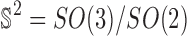 . But under the uniformity assumption,
  is not different from the average of
  over
over  , namely,
  . Thus it follows that, under the uniformity assumption, the EM averaged correlation
  in Equation (8) is equal to the projection of the SAXS data
  , when viewed as a 3D spherically symmetric function. This projection can be expressed in terms of the Abel transform (Bracewell, 2003, Ch. 9). The Abel transform of a 1D function
  is defined as
 |
This relation is easy to prove using Pythagoras's theorem and a simple change of variable. From our discussion it follows that
 |
which means that the average of the correlations of EM images equals the Abel transform of the SAXS data. In practice, we expect this equality to hold up to a scale, due to the fact that the sources for EM imaging and SAXS experiment have different amplitudes. We are tacitly assuming that the SAXS and EM data are based on the same physical properties of the complex. In reality, however, the EM images are formed based on the scattering of electron beams by, primarily, the nuclei of the atoms, whereas the SAXS data are formed based on the diffraction of X-ray beams by electrons in the atoms.
3.2. Evaluating the Abel transform: Accuracy issues
Our approach requires evaluating the Abel transform of the SAXS data  . In the Abel transform, the integrand is singular at
  . This can cause some error in evaluating the transform, especially when the SAXS data
  are known with only finite radial resolution or noise is high. Note that from Equation (10) for
  , the singularity is removed, and
  .
.
In general, there are two approaches in evaluating singular integrals: eliminating the singularity with a change of variable and ignoring the singularity (Davis and Rabinowitz, 1984). The first method essentially requires knowing the integrand with infinite accuracy, which is impractical in our application. However, the method of ignoring-the-singularity is practical, and as its name suggests requires no special provision. The caveat, however, is that the presence of a singularity adversely affects the rate of convergence in terms of the integration step size (El-Tom, 1971). We elaborate on this issue [following El-Tom (1971)].
Let  be continuous on
  . Assume that f can be written as
  with
with  ,
,  being a function whose derivative on
  exists is continuous and integrable in absolute value, that is,
  . Notice that under these conditions, the integral
  exists. Such a singularity is called an algebraic singularity (El-Tom, 1971). In the case of the Abel transform, we have
  , as for most densities
  and, hence,
  are smooth. Now, let us take the simple rectangle integration rule
  , the step size being
  . Note that, in this approximation, we are ignoring the singularity at
  (e.g., instead of writing
  , which obviously cannot be calculated). The approximation error is
  . It can be shown that
  with the rate
  (El-Tom, 1971). This means that for the Abel transform, the rate of convergence will be
  . It is interesting also to mention that even more complicated integration methods such as the midpoint, trapezoid, or quadrature rules have the same rate of convergence (El-Tom, 1971), although the actual error for a given step size might be different. To put this rate of convergence in perspective, note that if f is continuous on
  (no singularity,
  ), then the rate would be
  . Also recall that in the case of a function with smooth second-order derivative on
  , the convergence rate of the trapezoid and the midpoint rules improve to
  . Finally, we stress that the approximation error always exists (due to the discretization in computing the integral); however, in this case, due to the singularity, it is worse compared with the case of a nonsingular integrand.
Next, we perform a numerical experiment in the case of the SAXS data of a spherical object. Consider a spherical object of radius R and with uniform density, that is,
 |
For such a body, the correlation function is given by

This formula is derived using the formula for the intersection volume of two spheres. Due the spherical symmetry of  , we have
  . We use the rectangle integration method with various step sizes to evaluate the Abel transform of
  with
with  . Figure 1 shows the results for step sizes
  . Also the exact curve (calculated using Matlab's adaptive step size integration method) is shown. Clearly the slow rate of improvement in the accuracy matches the theory already explained.
FIG. 1.

The effect of integration step size in evaluating the Abel transform of  , Equation (12).
In our applications, we cannot have very small step sizes because usually the SAXS data are available on a finite grid and additionally the values at the grid nodes can be noisy. Notice that an interpretation of the mentioned error analysis is that if we have  at a resolution of
  , we get its Abel transform with an error of order
  . However, this also means that any error in
  may be amplified in
  . Thus, the net effect of the singularity is that we have to accept some moderate error in evaluating the Abel transform of
  and hence in the matching between the EM profile
  and the SAXS profile
  [Equation (10)]. This may hinder our ability to distinguish between complexes that have very similar SAXS data
  .
.
3.3. Removing the noise in EM planar correlations without class averaging
It is well known that the noise effect is extremely strong (i.e., low SNR) in EM images. The improvement of SNR usually has been done either by class averaging, that is, averaging many different images in a class corresponding to similar orientations (van Heel and Frank, 1981; van Heel, 1984; Schatz and Van Heel, 1990; Penczek et al., 1992; Penczek, 2002; Scheres et al., 2005; Park et al., 2011; Singer et al., 2011; Shkolnisky and Singer, 2012; Park and Chirikjian, 2014; Zhao and Singer, 2014), or by applying denoising techniques, such as bilateral filtering (Jiang et al., 2003) sinograms (Mielikäinen and Ravantti, 2005) and covariance Wiener filtering (Bhamre et al., 2016) to EM images. Note that the method we propose in this work is to remove the noise on a single image rather than over a class, which makes our work very different from others. Hereunder, we explain how we eliminate the noise on a single image.
Let us denote the noisy version of the image  by
by  . We assume an additive noise model (which is a reasonable assumption in the EM imaging mechanism). Thus we can write
 |
where  is the noise. If we assume that the noise is spatially white with zero mean and variance
  , and further that it is uncorrelated with the image
  , then we can see that
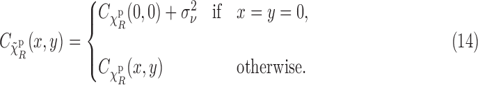 |
We have derived this equation under the ergodicity assumption, meaning that statistical and spatial averages are equal, which in practice holds to a good extent. Note that Equation (14) means that if we know or can estimate the noise variance  , then we can remove the effect of noise from the correlations
  . In practice, we may be able to estimate
  from parts of the image, where most likely the actual projection image of the complex is not present (e.g., the corners of the image).
4. Experiments
An important problem in structural biology is to determine the conformational states of a large biomolecular complex (e.g., open vs. closed). Both SAXS and EM experiments can be performed for this purpose, and in some cases we may want to verify whether the samples in the SAXS and EM experiments contain the complex at the same conformational state. We perform two simulated experiments on a synthetic model and one on a simulated complex with ligand-binding domains (LBDs).
4.1. Conformational states: The two-body model
We simulate different conformational states of a large biomolecular complex by modeling the complex with two solid ellipsoids of the same size and varying the (unknown) angle  between the principal axes of the two ellipsoids. We denote the complex at conformation associated with angle
  by
by  . The goal is to decide whether the EM and SAXS experiments were conducted on the complex at the same conformation in the respective samples, and also to examine the angular resolution that can be achieved. Before proceeding further, we stress that although our mathematical models were in spatially continuous setting, in the experiments we move to a discrete spatial setting.
The data are generated as follows. The axes lengths of each ellipsoid are  Å. A volume V of size
  (
( ) voxels is generated that contains the complex
  with conformational angle
  . The complex
  itself is modeled by a solid (uniform) body as explained earlier in Section 2. To simulate the EM experiment, the complex is rotated (inside V) around the center of V by a randomly (uniformly) generated rotation matrix R. Then a projection along the z-axis is computed, which results in an
  image. The top two images in Figure 2 show random projections of conformational angles of
  and
and  . Next samples of zero mean white Gaussian noise of variance
  are added to the images as shown in the second row of Figure 2. In the figure, the SNR is
  . For each image the SNR is defined as the average energy of the projection of the complex to the energy of the noise in that image;
  is determined accordingly (the energy of noise is
  ). In this experiment,
  random rotation matrices are uniformly generated on
  and corresponding to each rotation matrix
  noisy samples are generated. Thus a total of 1000 noisy images are generated.
FIG. 2.

The top row shows random EM projections of the two-body complex  at two conformational angles
  and
and  (see Section 4.1 for more details). The middle row shows the same images contaminated by noise (SNR
 ). The bottom row, graphs, shows the estimated corresponding SAXS and EM profiles [the left graph shows un-normalized profiles and the right graph shows the normalized profiles—see Equation (15)]. EM, electron microscopy; SAXS, small angle X-ray scattering; SNR, signal-to-noise ratio.
Next, the spatial correlation of each planar image is found. Notice that this results in a correlation image of size  . To simulate the noise-removal step described in Section 3.3, a patch of size
  pixels, where
  , at a corner of each image is selected and the variance of noise estimated in that patch. Then the variance of the noise is subtracted from the correlation at
  [see Equation (14)]; all such denoised correlations are averaged. The result is an almost circularly symmetric image. However, we further symmetrize it by circular averaging to get an approximation of
  . The circular averaging is performed at rather high angular resolution. Since the images are discrete spatially, for circular averaging we need to perform spatial interpolation. We also used interpolation to increase the resolution in the radial variable r to
  . This improves observation and smoothness of the results. To simulate the SAXS data generation, we simply find the 3D correlation of the volume V and perform spherical averaging (combined with spatial interpolation) to get an approximation of
  [see Equation (4)]. We obtain
  with resolution of
  .
.
Finally, to estimate the SAXS profile  , we use the rectangle integration rule. The bottom left plot in Figure 2 shows the graphs of the estimated EM profiles
  and SAXS profiles
  for conformational angles of
  and
and  . It can be seen that the corresponding SAXS and EM profiles are similar for moderate to large values of r. However, for small values of r, the SAXS profiles for both
  and
and  are becoming closer to each other and deviate from the EM profiles. The fact that the SAXS profiles for small r are very similar is expected, and reflects the fact that SAXS data can give low-resolution information about a structure. In fact, theoretically we have
  and
and  for small r, since in both conformations the total volume is the same and the individual bodies are the same. Thus effectively
  for small r. The observed discrepancy between the EM and SAXS profiles can be attributed to both noise and the integration error in evaluating the Abel transform. In the bottom right plot of Figure 2, we have plotted the normalized version of the EM and SAXS profiles, where each profile integrates to 1. Specifically, we define the normalized profiles as
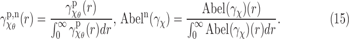 |
In practice, this normalization is very useful, primarily because the EM and SAXS profiles are, at best, proportional to each other and may differ in their scaling significantly since they come from very different experimental sources.
Next we perform a similar experiment to estimate the smallest resolvable angle. For that we define a notion of distance between the SAXS and EM profiles. Based on the forgoing discussion, the difference at small r may be very large but with very little relationship with the conformational angles. Thus we choose a value r0 and we compare the profiles for  . We choose a simple L2-based distance as
 |
Of course, in practice, a discretized version of this will be used. In particular, if we set  as 1 (note in simulation it is 0.5
  ), then the distance defined in Equation (16) simply becomes Euclidean vector norm, which can be easily computed. In this experiment, we chose the SNR much lower at
  . At this extremely low SNR, no vestige of the (projection of the) complex is visible. We generate conformations with angles
  . Table 1 shows the entries of a distance matrix, where each entry is the distance defined in Equation (16) between SAXS and EM profiles at respective indicated angles. All the distances are scaled by a fixed number for ease of presentation. We have chosen
  in Equation (16). As it can be seen, in some cases (underlined) the EM and SAXS profiles of angles that differ by
  can be closer than those of the actual (correct) angles. However, for differences larger than or equal to
  , such a confusion is not observed. Our experiments show that in a larger number of trials, confusion for angles larger than or equal to
  is very rare. Thus, the angular resolution is roughly
  with very high certainty.
Table 1.
A Distance Matrix for the Two-Body Model Experiment in Section 4.1
| SAXS | |||||||||
|---|---|---|---|---|---|---|---|---|---|
| EM | 30° | 35° | 40° | 45° | 50° | 55° | 60° | 65° | 70° |
| 30° | 0.29 | 0.52 | 0.97 | 0.76 | 1.28 | 1.39 | 1.66 | 1.91 | 1.88 |
| 35° | 0.21 | 0.28 | 0.66 | 0.49 | 0.99 | 1.11 | 1.38 | 1.66 | 1.63 |
| 40° | 0.48 | 0.29 | 0.34 | 0.29 | 0.68 | 0.83 | 1.08 | 1.40 | 1.37 |
| 45° | 0.82 | 0.56 | 0.19 | 0.37 | 0.37 | 0.55 | 0.77 | 1.12 | 1.09 |
| 50° | 1.11 | 0.83 | 0.43 | 0.61 | 0.21 | 0.34 | 0.49 | 0.85 | 0.83 |
| 55° | 1.37 | 1.08 | 0.71 | 0.86 | 0.35 | 0.30 | 0.26 | 0.61 | 0.60 |
| 60° | 1.58 | 1.28 | 0.94 | 1.07 | 0.57 | 0.42 | 0.20 | 0.41 | 0.41 |
| 65° | 1.75 | 1.46 | 1.15 | 1.26 | 0.77 | 0.58 | 0.34 | 0.27 | 0.28 |
| 70° | 1.88 | 1.59 | 1.31 | 1.41 | 0.94 | 0.74 | 0.50 | 0.25 | 0.26 |
Each entry shows the distance, Equation (16), between the SAXS and EM profiles at the corresponding body angles. All the distance values are normalized by a common factor for ease of presentation. The diagonal entries are in boldface. The underlined entries represent the cases where the distances between the SAXS and EM profiles of two different angles give a distance smaller than the correct angle.
EM, electron microscopy; SAXS, small angle X-ray scattering.
4.2. Glutamate receptor LBD conformations
Here, we perform a rather similar experiment while we generate the data from Protein Data Bank (PDB) (Berman et al., 2000). Specifically, we consider the LBD of glutamate receptor, which is known to play a crucial role in human brain activities such as memory formation and learning process (Dingledine et al., 1999). We consider three conformational states of LBD: “apo” or unliganded state (PDB entry: 1FTO), antagonist-bound state (PDB entry: 1FTL), and partial agonist-bound state (PDB entry: 1FTK). It is experimentally shown that the conformation of “apo” state is more similar to the antagonist-bound state than to the agonist-bound state (Madden et al., 2005). As we will see shortly, the same conclusion can be drawn from our simulation results. In our simulation, all atom coordinates were considered.
We simulate the effect of each atom by a 3Å × 3Å × 3Å cube of constant intensity centered at each atomic coordinate present in the corresponding PDB file of each complex. The rest of simulation is as in the previous example with volume size  ,
,  , number of random rotations
  , number of images per orientation
  , and patch size
  for denoising. In the first experiment, we compare the SAXS and EM profiles of complexes 1FTL and 1FTK. The top panels in Figure 3 show the atomic configuration of these two complexes. The left bottom graph shows the un-normalized SAXS and EM profiles for both. The large jump at
  is due to error in estimating the noise variance. As can be seen, the profiles of distinct conformations are easily separable despite the fact that the EM and SAXS of each complex differ slightly (due to noise and the singularity effect). Here, however, this difference for smaller values of r is significant, presumably because the total volume of 1FTL and 1FTK is substantially different. In the next experiment depicted in Figure 4, we compare the profiles of 1FTO and 1FTL. As can be seen, the two conformations are quite similar and their corresponding profiles also become indistinguishable, which conforms with the earlier mentioned fact that these two conformational states are close.
FIG. 3.

Comparing SAXS and EM profiles ( and
and  , respectively) and their normalized versions for 1FTL and 1FTK, see Section 4.2 for details.
FIG. 4.

Comparing SAXS and EM profiles ( and
and  , respectively) and their normalized versions for 1FTL and 1FTO, see Section 4.2 for details.
5. Effect of Preferred Orientations in Cryo-EM
So far, we have assumed that the sample in EM has uniformly distributed random orientations. However, it is well recognized that there are orientational preferences of the molecule on the specimen grid for EM (Frank, 2006), unlike SAXS that assumes uniform orientation of the sample molecule. This effect has been observed (Tischendorf et al., 1974; Lamy et al., 1982; Van Antwerpen, 2004; Liu et al., 2013) and is known to cause some problem in 3D reconstruction in EM. The origin of the orientational preferences depends on the types of the sample preparations: “negatively stained” and “frozen-hydrated” specimens (Frank, 2006). Usually orientational preferences are believed to come from many factors including carbon coating on the specimen grid (Liu et al., 2013), film thickness (Van Antwerpen, 2004), interaction of the molecule with the air–water interface (Grigorieff, 1998), and so on. These factors apparently limit the range of orientations that a molecule can take in the sample specimen grid. Also different molecules are expected to have different orientational preferences. In this section, we consider the orientational preferences in calculating the cryo-EM profile by investigating possible scenarios and the effects on the cross-validation data. To reflect the reality, we continue using the conformations of glutamate receptor LBD as in the previous section.
5.1. Imposing planar rotation restrictions at finite regions
One of the simplest possible scenarios would be the case where the orientations of the molecule selected from uniformly distributed random rotations have limitation such that only planar rotations are allowed. Physically, this mimics possible situations where a part of a molecule has a shape such that it can be stuck in a hole at the sample grid, in which case the molecule can have only planar rotation, and otherwise the molecule can have uniformly random orientations. We consider two possible scenarios as follows.
5.1.1. Case I
See Figure 5a for the graphical illustration. In the figure, noting that the Z-direction is parallel to the projection direction, what we impose in this scenario is as follows. We consider the angle  between z-axis of each body-fixed frame among 100 random orientations and the global Z-axis. To be more specific, let
  and
and  , respectively, denote the unit vectors for Z- and z-axis, viewed from the global frame. Then
  . Rotations that have
  smaller than
  (i.e.,
  ) are not allowed to have the originally assigned random rotations, rather they are allowed to rotate only about Z-axis. The rotation angles are randomly selected. In other words, the rotations that local z-axes fall into the cone (denoted as red dotted line in Fig. 5a) are replaced by
  where
where  is a uniformly distributed random angle.
FIG. 5.

Schematics that illustrate the possible scenarios for the preferred orientations. (a) Cases I and II, (b) Case III, (c) Case IV, and (d) Case V. In (a, c, and d),  describes the size of the conical regions. See Section 5 for details.
5.1.2. Case II
We can consider the opposite situation to case I. Whereas the previous case imposes the constraint that when  falls into a cone area, then the orientations of the molecule are confined to only planar rotations about Z-axis. Here we consider the reverse situation: planar rotation confinement is applied to the orientations when
  . Graphically, in Figure 5a, areas other than cone have this planar rotation restriction.
5.2. Preferences by exact rotational axes: Case III
So far we considered the cases where the restrictions were imposed such that some regions among random orientations are limited to planar orientations instead of all random rotations. Based on what has been reported so far, it is more likely that specific ranges of the orientations of the molecule are allowed. As nicely illustrated in Figure 5 in Van Antwerpen (2004), the orientations of the molecule in the specimen grid are limited to only around a finite set of orientations. This suggests a strong possibility that the orientations are likely to be clustered.
To investigate this, first, let us consider the following scenario. Here we represent the orientations with axis–angle parameterization (i.e., rotation axis and the rotation angle about the axis). First, we seed 100 random unit vectors in the space. These unit vectors represent rotational axes. Then we select a number of vectors among them. This way we can select the axes of the “preferred orientations”. Regarding rotational angles about each rotational axis, to each vector, fine-grid values of angles are assigned (e.g., 100 rotational angles are evenly distributed in  ). Physically, this mimics the situation where there are limited number of rotational axes that the molecule can take, but the molecule can rotate freely around those axes.
5.3. Preferences by random conical selection
Going further, motivated by the random conical data collection method [see (Frank, 2006) and references therein], we consider the following two additional scenarios. Basically, in these scenarios, orientational preference exists only in selected conical regions, as shown in Figure 5c and d. In the figures, cones denoted in red-dotted line in the figure represent the selected conical regions (the criterion will be explained later). The arrows that fall into these conical regions represent the selected rotations, whereas arrows in blue represent the rotations that are not selected among uniformly random rotations that are initially seeded.
5.3.1. Case IV
In this case, the selected conical regions are obtained by considering local z-axes of the body-fixed frames. First, we seed a finite number of uniformly distributed random rotations (e.g., 1000 or even 5000 to maintain the number of selected rotations around 100 or more). Among them, we randomly select a small number of rotations where the unit vectors of the corresponding local z-axes are denoted as  . Then we consider the remaining rotations (the corresponding z-axes are denoted as e3), and select those that satisfy
  where
where  .
.  denotes the size of the cones. These selected rotations represent the preferred orientations.
5.3.2. Case V
In this case, instead of considering local z-axes, we consider the rotational axis of the rotation (denoted as a unit vector n in Fig. 5d) to select possible orientations of the molecule. To be more specific, let  denote the rotational axis of each selected rotation among a finite number of uniformly distributed random rotations. Among the remaining rotations, we select the rotations that satisfy
  where
where  , n being the rotational axis of the remaining rotations.
5.4. Results
For cases I and II, the only parameter  was chosen among 10°, 30°, 50°, 70°, 100°, 120°, 150°, and 180°. For case III, the number of selected directions was chosen from a set of 1 to 5. For cases IV and V that require two parameters defining the cone size and the number of selected rotations,
  and the number of directions were chosen between 10° and 30° and among 1, 3, and 5, respectively. For all individual cases, we repeated the simulation five times to reflect the stochastic nature of the selection of the corresponding rotations that satisfy the criterion.
The results of cases I to V for glutamate ligand receptor domains are shown in Figures 6–8. Error bars in the figures denote the standard errors of the mean. Since we are interested in the EM profile, as a quantification, we use the distance between two projected EM profiles calculated as L2-based distance as
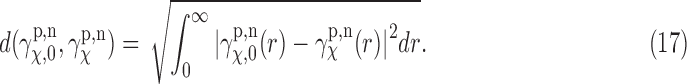 |
FIG. 6.

Plots of the distance between two EM profiles calculated using Equation (17). Error bars in the figures denote the standard errors of the mean (SEM). These correspond to cases I and II. Detailed explanation can be found in Section 5.4.
FIG. 7.

Distance plots for case III. Distances are calculated using Equation (17). Error bars in the figures denote the SEM. Details can be found in Section 5.4.
FIG. 8.

Distance plots for cases IV and V. Distances are calculated using Equation (17). Error bars in the figures denote the SEM. Details can be found in Section 5.4.
Again, for a practical purpose, we use a discretized version of this as in the earlier section. Note that in computing EM profile, we do not need to worry about the singularity at  , which is reflected in the lower bound of the integral. Here,
  denotes the profile obtained from uniformly random rotation case, which is a reference for our purpose.
  then denotes the profile calculated according to different cases. To give a sense of how close two profiles are in terms of the distance, we compute the distance defined in Equation (17) from the normalized EM profiles shown in Figures 4 and 3. For the cases of 1FTL and 1FTO where they are structurally very close to each other (see the normalized profiles in dotted lines in Figure 4 that are almost identical), the distance is computed as 0.005, whereas for the cases of 1FTL and 1FTK (see the normalized profiles in Fig. 3), the distance between the corresponding EM profiles is 0.051. Our individual comparison between large sets of EM and SAXS profile data obtained by the simulation shows that, if the distance between two EM profiles is up to about 0.01, then the EM and SAXS profiles can be considered as close as in Figure 4. For example, if the discrepancy of the distances become about 0.02, then we can see clearly the difference between SAXS and EM profiles.
Figure 6 shows that cases I and II have a common trend. First, by noting that cases I and II are mutually reverse scenarios, the distributions of distance are seen to be reflected vertically when comparing a, c, and e with b, d, and f. It can be seen that when  becomes larger than about 50° or so (described in terms of a, c, and e, i.e., case I), the distance becomes larger than 0.01, which means that the profile is effectively affected by the preferences. The interesting finding is that when
  or so, the discrepancy between uniform random rotation case and case I becomes large and is not influenced by the cone size (i.e.,
  ) any more. These results clearly suggest that orientational preferences in EM have the possibility to impact the cross-validation of SAXS and EM data.
When we consider case III, however, we can see that this type of orientational preferences does not influence the validation of SAXS and EM data much. As shown in Figure 7, the distance between EM profiles is small (around 0.005 and up to 0.01), which leads to a excellent match between SAXS and EM data, as mentioned earlier. One case in Figure 7c, where the number of directions is 1 in 1FTK, is seen to have larger distance value, but still around 0.01, which is not as bad in terms of cross-validation. Moreover, in this scenario, what would occur in reality is such that there should be more than one direction. Hence, this type of orientational preferences does not have much impact on the cross-validation.
In contrast, cases IV and V seem to exhibit relatively large variation compared with the previous scenarios. To be more specific, Figure 8a–d (1FTL and 1FTO cases) demonstrates small distance distributions, whereas Figure 8e and f exhibits large variation in distance distribution. In other words, 1FTL and 1FTO are not affected much by these types of scenarios. However, for 1FTK, EM and SAXS data can be considered cross-validated only when the size and the number of selected conical area are larger. As a matter of fact, in previous scenarios, 1FTK exhibits larger distance distributions than 1FTL and 1FTO. This is, in part, due to the fact that the conformations of 1FTL and 1FTO have more prominent rotational symmetries than conformations of 1FTK [see Armstrong and Gouaux (2000) for detailed structural information]. To explain the effect of rotational symmetry, as an analogy, we consider an exact spherical molecule, then the profiles that are computed through our method will not be affected by any preferred orientations. In fact, there will be no preferred orientation in this case. Hence the more prominent symmetry a molecule takes, the less affected the profile is by the preferred orientations. What the results suggest is the possibility of limitation on the cross-validation due to the orientational preferences. In particular, if the preferred orientations that a molecule can take occupy a very small region in the rotational space (i.e., small  and small number of directions), then it is likely that this type of orientational preference will affect the validation. In total, the results suggest that our validation method works well in many of the situations with possible limitations due to the orientational preferences in EM experiments.
6. Conclusions
We presented a simple and fast approach to check the compatibility of SAXS and cryo-EM data. By noting that the SAXS data are indeed derived from the correlation function (i.e., the Patterson function, which is the self-convolution of the density function), in this article, we proposed a method based on the correlation functions in both SAXS and EM, and we derived the basic mathematical methodology. In particular, we used the fact that averaging the correlation functions of EM images (before 3D reconstruction) is equivalent to the Abel transform of the SAXS data. Then we investigated the plausibility of our approach with simulated data and the actual PDB data. We also discussed limitations due to the singularity in the Abel transform in SAXS and the noise effect in EM images. To answer an important question on the effect of preferred orientations in our results and simulations, we considered several possible scenarios that can mimic the preferred orientations. The results suggest that our validation method is credible in many situations, with the existence of the possibility that the orientational preferences influence the cross-validation of the data. Further detailed study with experimental data will clarify the limitation due to the orientational preferences. This study is a first step toward the fusion of two different experimental modalities, which, in turn, will enhance the understanding of the relationship between the function and the shape of large bimolecular complexes.
Acknowledgment
Research reported in this publication was supported by the National Institute of General Medical Sciences of the National Institutes of Health under award number R01GM113240.
Author Disclosure Statement
No competing financial interests exist.
References
- Afsari B., Kim J.S., and Chirikjian G.S. 2015. Cross-validation of data in SAXS and cryo-EM. In Proceedings of IEEE International Conference on Bioinformatics and Biomedicine (BIBM), 1224–1230. Washington, DC [Google Scholar]
- Armstrong N., and Gouaux E. 2000. Mechanisms for activation and antagonism of an AMPA-sensitive glutamate receptor: Crystal structures of the GluR2 ligand binding core. Neuron 28, 165–181 [DOI] [PubMed] [Google Scholar]
- Berman H., Westbrook J., Feng Z., et al. 2000. The Protein Data Bank. Nucleic Acids Res. 28, 235–242 [DOI] [PMC free article] [PubMed] [Google Scholar]
- Bhamre T., Zhang T., and Singer A. 2016. Denoising and covariance estimation of single particle cryo-EM images. J. Struct. Biol. 195, 72–81 [DOI] [PMC free article] [PubMed] [Google Scholar]
- Blanchet C.E., and Svergun D.I. 2013. Small-angle X-ray scattering on biological macromolecules and nanocomposites in solution. Annu. Rev. Phys. Chem. 64, 37–54 [DOI] [PubMed] [Google Scholar]
- Bracewell R. 2003. Fourier Analysis and Imaging. Springer Science & Business Media, New York [Google Scholar]
- Bron P., Giudice E., Rolland J.-P., et al. 2008. Apo-Hsp90 coexists in two open conformational states in solution. Biol. Cell 100, 413–425 [DOI] [PubMed] [Google Scholar]
- Davis P.J., and Rabinowitz P. 1984. Methods of Numerical Integration. Academic Press, New York [Google Scholar]
- Dingledine R., Borges K., Bowie D., et al. 1999. The glutamate receptor ion channels. Pharmacol. Rev. 51, 7–61 [PubMed] [Google Scholar]
- Dong H., and Chirikjian G.S. 2014. A computational model for data acquisition in SAXS. In BDB’14 Proceeding of the 5th ACM Conference on Bioinformatics, Computational Biology, and Health Informatics, 695–702, Newport Beach, CA, USA [Google Scholar]
- Dong H., Kim J.S., and Chirikjian G.S. 2015. Computational analysis of SAXS data acquisition. J. Comput. Biol. 22, 787–805 [DOI] [PMC free article] [PubMed] [Google Scholar]
- El-Tom M. 1971. On ignoring the singularity in approximate integration. SIAM J Numer Anal 8, 412–424 [Google Scholar]
- Feigin L., Svergun D.I., and Taylor G.W. 1987. Structure Analysis by Small-Angle X-ray and Neutron Scattering. Springer [Google Scholar]
- Frank J. 2002. Single-particle imaging of macromolecules by cryo-electron microscopy. Annu. Rev. Biophys. Biomol. Struct 31, 303–319 [DOI] [PubMed] [Google Scholar]
- Frank J. 2006. Three-Dimensional Electron Microscopy of Macromolecular Assemblies. Oxford University Press, New York [Google Scholar]
- Grigorieff N. 1998. Three-dimensional structure of bovine NADH: Ubiquinone oxidoreductase (complex I) at 22 A in ice. J. Mol. Biol. 277, 1033–1046 [DOI] [PubMed] [Google Scholar]
- Jiang W., Baker M.L., Wu Q., et al. 2003. Applications of a bilateral denoising filter in biological electron microscopy. J. Struct. Biol. 144, 114–122 [DOI] [PubMed] [Google Scholar]
- Lamy J., Sizaret P., Frank J., et al. 1982. Architecture of Limulus polyphemus hemocyanin. Biochemistry 21, 6825–6833 [DOI] [PubMed] [Google Scholar]
- Liu Y., Meng X., and Liu Z. 2013. Deformed grids for single-particle cryo-electron microscopy of specimens exhibiting a preferred orientation. J. Struct. Biol. 182, 255–258 [DOI] [PMC free article] [PubMed] [Google Scholar]
- Madden D.R., Armstrong N., Svergun D., et al. 2005. Solution X-ray scattering evidence for agonist- and antagonist-induced modulation of cleft closure in a glutamate receptor ligand-binding domain. J. Biol. Chem. 280, 23637–23642 [DOI] [PubMed] [Google Scholar]
- Mielikäinen T., and Ravantti J. 2005. Sinogram denoising of cryo-electron microscopy images. Lect. Notes Comput. Sci. 3483, 1251–1261 [Google Scholar]
- Natterer F. 1986. The Mathematics of Computerized Tomography, volume 32 SIAM, Philadelphia [Google Scholar]
- Park W., and Chirikjian G.S. 2014. An assembly automation approach to alignment of noncircular projections in electron microscopy. IEEE Trans. Autom. Sci. Eng. 11, 668–679 [Google Scholar]
- Park W., Midgett C.R., Madden D.R., et al. 2011. A stochastic kinematic model of class averaging in single-particle electron microscopy. Int. J. Rob. Res. 30, 730–754 [DOI] [PMC free article] [PubMed] [Google Scholar]
- Penczek P.A. 2002. Three-dimensional spectral signal-to-noise ratio for a class of reconstruction algorithms. J. Struct. Biol. 138, 34–46 [DOI] [PubMed] [Google Scholar]
- Penczek P.A., Radermacher M., and Frank J. 1992. Three-dimensional reconstruction of single particles embedded in ice. Ultramicroscopy 40, 33–53 [PubMed] [Google Scholar]
- Schatz M., and Van Heel M. 1990. Invariant classification of molecular views in electron micrographs. Ultramicroscopy 32, 255–264 [DOI] [PubMed] [Google Scholar]
- Scheres S.H., Valle M., Nuñez R.N., et al. 2005. Maximum-likelihood multi-reference refinement for electron microscopy images. J. Mol. Biol. 348, 139–149 [DOI] [PubMed] [Google Scholar]
- Shkolnisky Y., and Singer A. 2012. Viewing direction estimation in cryo-EM using synchronization. SIAM J. Imaging Sci. 5, 1088–1110 [DOI] [PMC free article] [PubMed] [Google Scholar]
- Singer A., Zhao Z., Shkolnisky Y., et al. 2011. Viewing angle classification of cryo-electron microscopy images using eigenvectors. SIAM J. Imaging Sci. 4, 723–759 [DOI] [PMC free article] [PubMed] [Google Scholar]
- Svergun D.I., and Koch M.H. 2003. Small-angle scattering studies of biological macromolecules in solution. Rep. Prog. Phys. 66, 1735. [DOI] [PubMed] [Google Scholar]
- Svergun D.I., Koch M.H., Timmins P.A., et al. 2013. Small Angle X-Ray and Neutron Scattering from Solutions of Biological Macromolecules. Oxford University Press, New York [Google Scholar]
- Tischendorf G.W., Zeichhardt H., and Stöffler G. 1974. Determination of the location of proteins L14, L17, L18, L19, L22, and L23 on the surface of the 50S ribosomal subunit of Escherichia coli by inmmunoelectron microscopy. Mol. Gen. Genet. 134, 187–208 [DOI] [PubMed] [Google Scholar]
- Van Antwerpen R. 2004. Preferred orientations of LDL in vitreous ice indicate a discoid shape of the lipoprotein particle. Arch. Biochem. Biophys. 1, 122–127 [DOI] [PubMed] [Google Scholar]
- van Heel M. 1984. Multivariate statistical classification of noisy images (randomly oriented biological macromolecules). Ultramicroscopy 13, 165–184 [DOI] [PubMed] [Google Scholar]
- van Heel M., and Frank J. 1981. Use of multivariate statistics in analysing the images of biological macromolecules. Ultramicroscopy 6, 187–194 [DOI] [PubMed] [Google Scholar]
- Van Heel M., Schatz M., and Orlova E. 1992. Correlation functions revisited. Ultramicroscopy 46, 307–316 [Google Scholar]
- Vestergaard B., Sanyal S., Roessle M., et al. 2005. The SAXS solution structure of RF1 differs from its crystal structure and is similar to its ribosome bound cryo-EM structure. Mol. Cell 20, 929–938 [DOI] [PubMed] [Google Scholar]
- Zhao Z., and Singer A. 2014. Rotationally invariant image representation for viewing direction classification in cryo-EM. J. Struct. Biol. 186, 153–166 [DOI] [PMC free article] [PubMed] [Google Scholar]