

Abstract
Monitoring bodily pressures provide valuable diagnostic and prognostic information. In particular, long-term measurement through implantable sensors is highly desirable in situations where percutaneous access can be complicated or dangerous (e.g., intracranial pressure in hydrocephalic patients). In spite of decades of progress in the fabrication of miniature solid-state pressure sensors, sensor drift has so far severely limited their application in implantable systems. In this paper, we report on a universal packaging technique for reducing the sensor drift. The described method isolates the pressure sensor from a major source of drift, i.e., contact with the aqueous surrounding environment, by encasing the sensor in a silicone-filled medical-grade polyurethane balloon. In-vitro soak tests for 100 days using commercial micromachined piezoresistive pressure sensors demonstrate a stable operation with the output remaining within 1.8 cmH2O (1.3 mmHg) of a reference pressure transducer. Under similar test conditions, a non-isolated sensor fluctuates between 10–20 cmH2O (7.4–14.7 mmHg) of the reference, without ever settling to a stable operation regime. Implantation in Ossabow pigs demonstrate the robustness of the package and its in-vivo efficacy in reducing the baseline drift.
Index Terms: Baseline drift, Pressure sensor, Sensor packaging, Implantable sensors
I. INTRODUCTION
Measurement of physiological pressures is often used for diagnosis and evaluation of therapeutic interventions. These range from the non-invasive blood pressure measurement during an office visit to indwelling pressure sensors used in intensive care units [1], [2]. In certain situations, such as measurement of the intracranial pressure (ICP), where one needs access to a cranial space, the measurement require a high level of technical competence and must be performed in a sterile clinical setting [3]. In such cases, it is advantageous to use implantable sensors, in particular if pressure needs to be monitored for a long period of time [4]. Efforts in the area of implantable pressure sensors have been hampered by the sensor drift, in particular base-line drift, which degrades the measurement accuracy over time. This is in particular serious if re-calibration cannot be easily performed (e.g., intracranial pressure). The major sources of drift in implantable pressure sensors are related to the environmental factors, in particular absorption of moisture and bodily fluids by the material used in the sensor’s packaging. Polymeric materials used for device packaging and protection are in particular hygroscopic and can absorb a significant amount of moisture, resulting in package stress which can be transmitted to the sensing element, Figure 1. Most efforts to reduce the base-line drift have been focused on packaging and material know how. One solution adopted by Data Sciences International (https://www.datasci.com/) in their implantable systems is to place the sensor inside a hard-shell package along with other electronic components and connect it to the source of pressure via a gel-filled catheter (reported base-line drift of 2–3 mmHg after several months of implantation [5], [6]). Other groups have reported on low-drift sensors utilizing custom-made packages that are carefully designed and fabricated to avoid the use of any polymeric materials in the device and packaging [7], [8]. For example, Kroin et al. have reported on a titanium capacitive pressure sensor for intracranial applications having an average of 0.3 mmHg drift after 3–6 months of implantation [8]. Another notable example is the MEMS-based implantable pressure sensors commercialized by CardioMEMS (http://www.sjm.com/cardiomems) in which a complete-glass structure removes many sources of drift associated with disparate polymeric materials used in the package (although no data on long-term drift is made public, the device has been successfully implanted in human subject for many months [9], indicating a low-drift operation).
Figure 1.

Sources of drift for implantable pressure sensors with the most important source being the absorption of water and bodily fluid onto the packaging materials. Isolating the sensor by immersion in a non-aqueous fluid can significantly reduce the drift.
As discussed above, designs and manufacturing methods reported for low-drift implantable pressure sensors often require complicated steps and in-house expertise, which can hamper wider adoption of the techniques by the clinical and research communities. In this paper, we present a low cost and universal/generic solution to reduce the baseline drift by isolating the sensor in a silicone-filled balloon. The concept is validated by monitoring the baseline drift in an in-vitro aqueous environment and an in-vivo porcine model (Ossabow pig).
II. Fluid-Isolated Package Design and its fabrication process
The universal fluidic-isolation packaging technique reported here employs a modular design approach and is adaptable to many implantable systems. Such modular design physically separates the sensor and the rest of the system (readout and wireless transmission circuitry) while allowing the sensor to maintain a small form factor and be placed near the source of pressure (i.e., target organ). Figure 2 depicts a schematic of the packaging technique in which the sensor is isolated from the aqueous environment by complete encapsulation in a medical-grade thin polyurethane balloon filled with a biocompatible incompressible fluid. The packaging requires an inert non-aqueous fluid such as silicone oil to avoid any interaction with the sensing element and associated polymeric materials (e.g., Parylene-C or epoxy glue used in packaging) used in the assembly of the sensor. It is important that the balloon enclosing the fluid and the sensing element to be chemically resistant to the biological environment, strong, and impermeable to both isolation and body fluids. A thin wall medical-grade polyurethane balloon fulfills these requirements.
Figure 2.

Schematic view of the universal fluidic-isolation packaging technique for low-drift implantable pressure sensors.
The sensor packaging procedure is illustrated in Figure 3. Described packaging technique can be applied to any conventional diaphragm-based pressure sensor. In the prototype development, a commercial piezoresistive pressure sensor was used (Measurement specialties, MS5637-02BA03), Figure 3(a). The sensor is intended for barometric pressure measurement (dynamic range of 225–900 mmHg (306–1224 cmH2O) and resolution of 0.08 mmHg (0.1 cmH2O)); however, it can be adapted for biomedical purposes with proper packaging. This particular sensor has also an on-board temperature sensor and its internal microcontroller automatically compensates for temperature variations. This removes the need for using a temperature-controlled oven that is typically used for in-vitro validation experiments. The sensor has a small form factor (3×3×0.9 mm3), enabling for wide adoption in medical applications.
Figure 3.

Fabrication procedure showing the pressure sensor (a) mounted on a flexible cable interconnect (b) and encapsulated in a silicone oil-filled balloon (c–e), (f) an optical picture of a prototype; implant suture anchors are added for robust fixation to the tissue.
The packaging starts with bonding the pressure sensor to a custom-made (EPEC LLC) polyimide flexible cable containing electrical interconnects for interfacing with the electronic circuitry (the polyimide flexible cable is designed to have a certain length at both the distal and proximal ends to provide for a full encapsulation by the medical-grade balloon). After mounting and securing the sensor to the polyimide cable, a thin layer of parylene-C (5 μm) is deposited on the assembly for passivation, Figure 3(b). Note that the fabrication was done under clean-room condition up to this point. Subsequently, the sensor is encased in a thin (31–44 μm), medical-grade, polyurethane balloon (Vention Medical, 06001000CA) [10], Figure 3(c). The balloon used in our prototype is 10 mm in length, 6 mm in diameter in the middle section, and 2.5 mm in diameter in the proximal/distal ends. Following the placement of the sensor inside the balloon, the proximal junction of the balloon with the flexible cable is sealed using a UV-curable acrylated urethane adhesive (Loctite, 3106 cured under a UV lamp, 100 mW/cm2 for 5 minutes). The adhesive offers a leak-proof seal over the polyurethane [11]. After closing the proximal end, with the assembly being held upright, incompressible fluid (silicone oil, Sigma-Aldrich, Dow Corning 200 fluid for our study) is injected from the open distal end to fill the balloon, Figure 3(d). A small amount of UV curable adhesive is carefully dispensed after filling. Since the density of the adhesive is lower than silicone oil, it forms a thin layer on top. After UV-curing, extra adhesive is applied to prevent any leakage, Figure 3(e). Figure 3(f) shows photograph of a fabricated prototype having an overall size of 3 cm in length and 5 mm in diameter (scale bar indicates 1 cm).
III. Experimental Results
A. In-Vitro Characterizations
The prototypes were evaluated in-vitro by comparing them with: 1) a commercial reference pressure sensor (called reference from here on) and 2) another sensor without the fluid-isolation packaging (i.e., parylene C coated sensor in direct contact to saline, Figure 3(b)) served as the control (called unpackaged sensor from here on). Figure 4 illustrates the experimental setups. For in-vitro calibration, Figure 4(a), the packaged sensor was placed in a pressure chamber filled with phosphate buffered saline (PBS) solution and connected to a syringe pump and a commercial in-line pressure gauge (reference) (Omega DPG4000) (oil was dispensed on the top of saline solution to prevent evaporation). The calibration and stability of the reference pressure gauge was confirmed from the NIST traceable calibration certifications and 3-known pressure points calibration against the water-column pressure gauge before and after long-term experiments. Both packaged and unpackaged sensors were soaked in the PBS solution at room temperature (on-board temperature sensor automatically compensated for temperature variations in the lab). The difference in the pressure readings as compared to the reference sensor was recorded for 100 days.
Figure 4.

In-vitro experiment setups for (a) comparison with a standard reference pressure sensor (i.e., calibration), (b) comparison with an un-packaged pressure sensor (i.e., control), and (c) invivo experimental setup to compare with a clinical urodynamic machine equipped with a pump and a catheter-tip-mounted pressure transducer.
Figure 5 shows calibration results for the balloon-packaged fluidic-isolated sensor (vs. the reference sensor), illustrating a very good correlation (R2 = 0.98, slope of 1.06 ± 0.01) between the two. The temporal pressure measurements of the packaged sensor also closely followed the reference, Figure 5(a), indicating a faithful transmission of pressure across the balloon and silicone-oil. Figure 6 shows the time-series of pressure baseline drift compared to the reference sensor. Three packaged sensors were prepared and soaked in PBS solution. As can be seen, an initial aging effect with small fluctuations (±4 cmH2O) was observed in all three sensors in the first 30 days, settling down to a stable baseline after 40 days and remaining within 1.8 cmH2O (1.3 mmHg) of the reference. After 30-day of aging, the package of one sensor was removed to create a control sample (unpackaged sensor). This sensor, subsequently, showed large fluctuations (>10 cmH2O) and did not settle to a stable baseline (fluctuated between 10–20 cmH2O (7.4–14.7 mmHg) of the reference, without ever settling to a stable operation regime). This indicates an on-going process, which is mostly due to the absorption of water into the packaging materials and resulting slow degradation of certain materials under the ionic aqueous conditions. We believe that the source of the initial aging effect is partly due to the continuous operation of the sensor in the power-up mode which can result in certain aging process in the components, settling down after 30 days (< ±2 cmH2O). This is a common phenomenon reported by other investigators [7, 8]
Figure 5.

(a) Pressure measurements comparing the packaged and reference sensors, (b) linear regression showing pressure measured by the balloon-packaged sensor and the reference sensor.
Figure 6.

In-vitro long-term validation of packaging method; two packaged and one unpackaged sensor were soaked in saline at room temperature.
Figure 7 shows the linear regression of the normalized readings of the pressures against the references sensor. Figure 7(a)–(d) depicts the packaged sensors during the first 30 days and subsequent period (the regression analysis was separated for these two periods). The pressure measurements of packaged sensors as compared to the reference in the first 30 days show an average slope of 0.915 (with an average intercept of 0.083) indicating a small (5%) sensitivity change and an average baseline drift of 2.9 cmH2O, Figure 7(a), (c). However, after day 30, the sensors showed virtually identical sensitivities with negligible baseline drifts; an average slope was 0.984 with an average intercept of 0.015 and average baseline drift was 1.17 cmH2O (0.86 mmHg) or 0.011 cmH2O/day from day 31 to day 100, Figure 7(b), (d). The unpackaged sensor, meanwhile, shows a slope of 0.070 (with intercept of 0.931), indicating a significant sensitivity and baseline drift. Figure 7(f) shows the box plots representing the range of pressure readings; both packaged pressure sensors have variations within 4 cmH2O range, while the unpackaged one shows a range of 26.22 cmH2O.
Figure 7.

In-vitro long-term validation of packaged sensors from the soak test. Linear regressions of the packaged sensor # 1 from (a) day 1 to day 30 and (b) day 31 to day 114; packaged sensor # 2 from (c) day 1 to day 30 and (d) day 31 to day 114; (e) unpackaged sensor (control) from day 1 to day 100; (f) box-plot showing the overall pressure range variations for packaged and unpackaged sensors
These results clearly demonstrate that the described fluidic-isolation packaging method is capable of protecting the sensors against saline solution (i.e., aqueous environment) for an extended period. The table 1 compares the described packaging method with other reported low-drift implantable pressure sensors. As can be seen, our simple and generic packaging technique yields baseline drifts that are very similar to some of the lowest ones reported in the literature, all of which rely on more sophisticated material selection and manufacturing methods.
Table 1.
Baseline drift of the presented sensor as compare to other reported low-drift implantable pressure sensors.
| Ref. | Investigated period | Packaging material | Experiment type | Baseline drift |
|---|---|---|---|---|
| [5, 6] | 8–47 wk | (commercial) | In-vivo | Within 2–3 mmHg of reference |
| [7] | 230 days | Pyrex glass + Titanium | In-vivo | Within 1–2 mmHg of reference |
| [8] | 90–245 days | Titanium | In-vivo | Within 0.3 mmHg of reference |
| This work | 100 days | Silicone oil + Polyurethane | In-vitro | Within 1 mmHg of reference |
B. In-Vivo Tests
We also implanted our pressure sensor in the bladder wall of Ossabow miniature pig. The study was approved by the Institutional Animal Care and Use Committee at Indiana University School of Medicine. Pre- and post-implant calibrations were performed using a clinical urodynamic studies equipment (Laborie Delphis machine, Laborie, Toronto, Canada), Figure 4(c). The urodynamic system measures the maximum and minimum pressures that a bladder can hold using a catheter-tip-mounted pressure transducer (PBS solution is pumped into the bladder during the measurements). The calibrations were done to measure the bladder pressure when filled with 0 to 1500 cc of PBS (filling and voiding). In order to reduce the effects of initial aging processes, the pressure sensors were pre-soaked in PBS for 30 days prior to the implantation. The packaged sensors were implanted beneath the bladder mucosa [12] and were connected to a sub-cutaneous module housing the interface electronics and RF transmitter via the polyimide flex cable [13]. Figure 8 shows a photograph of the packaged sensor taken during the implantation.
Figure 8.
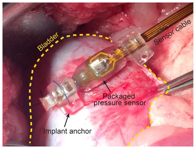
Photograph showing the packaged sensor implanted in bladder mucosa.
In order to reduce the animal distress and bladder infection during the experiments, the approved protocol did not allow bladder catheterization and cross-correlation measurements with the urodynamic system on a daily basis. Therefore, the only cross-referencing measurements were the ones performed under anesthesia at the beginning and termination of the experiments (when the device was implanted and explanted). In spite of this limitation, one can still make reasonable deductions regarding the cumulative sensor drift for the duration of the implant by measuring and characterizing the sensor immediately following ex-plantation.
Figure 9 shows the in-vivo pressure measurement results of two implanted packaged sensors (immediately post-surgical placement but prior to the start of long-term measurements). Figures 9 (a) and (b) show the pressure levels vs. time as compared to the readouts acquired by the urodynamic system (reference). The packaged sensors were able to closely track the intra-vesical measurements via the catheter-based sensor. The pressure measurements were also analyzed using the linear regression, Figure 9 (c), (d), with resulting slopes of 1.03 and 0.979 and R-square values of 0.93 and 0.98, respectively, indicating a strong correlation. After initial in-vivo calibrations and subsequent transfer of the animal to a care facility, the bladder pressures were wirelessly monitored for a period of 12 days [13]. Figure 10 shows the pressure measurements during the investigation period. In both plots, the very first peak indicates the calibrations (equivalent to Figure 9(a) and (b)). All bladder pressures measured during the experiment period fell within the minimum and maximum pressure range that the bladder can handle, in other words, there were no outlier. The insets in Figure 10 show close-ups of daily urinary activities, clearly indicating the bladder function during the day and night; the bladder typically has a higher pressure (> 10 cmH2O) during the daytime and a lower pressure (< 10 cmH2O) during the nighttime.
Figure 9.

In-vivo validation of the packaged sensors: (a), (c) pressure measurements comparing the packaged sensor 1 and reference sensors and its linear regression, (b), (d) pressure measurements comparing the packaged sensor 1 and reference sensors and its linear regression; statistical analysis shows identical pressure levels inside of bladder and beneath the bladder mucosa.
Figure 10.

In-vivo pressure measurements over time: the left most collected data is the calibration. All daily pressure measurements fell within the expected range.
The packaged sensors were explanted after the investigation period. Before removing the devices, the sensors were re-calibrated against the urodynamic system to investigate the baseline drift during the in-vivo experiment. The two-point calibration showed that the sensor performance remained virtually identical after 12 days showing less than 1% variations in both sensitivity and baseline. Although due to the abovementioned protocol limitation and technical difficulties, we could not collect in-vivo data for a longer stretch of time, we feel confident that encapsulating the sensor in an inert non-aqueous medium can significantly reduce the drift.
IV. Conclusion
We reported on a generic packaging method to reduce baseline drift in implantable pressure sensors. The technique is based on encapsulating the sensor in a silicone-filled medical grade polyurethane balloon in order to isolate the sensing element from the aqueous environment, a major source of drift in implantable sensors. Long-term in-vitro soak tests clearly indicated that the universal fluidic-isolation packaging technique can minimize the baseline drift to extremely low values. Packaging technique robustness and efficacy was also evaluated by implantation into sub-mucosal layer of a diabetic porcine animal model.
Acknowledgments
Authors would like to thank to Dr. SeungHyun Song for valuable discussions. This work was supported in part by a Project Development Team within the ICTSI NIH/NCRR Grant Number RR025761 and NIDDK DiaComp Pilot & Feasibility project, DK076169 (Powell, PI) and NIH grant HL 062552 (Sturek, PI).
References
- 1.Fleming DG. Indwelling and implantable pressure transducers. Cleveland, OH: CRC; 1977. [Google Scholar]
- 2.Tagawa T, Tamura T, Oberg PA. Biomedical sensors and instruments. CRC Press; 2011. [Google Scholar]
- 3.Schuhmann MU, Czosnyka M, editors. Intracranial Pressure and Brain Monitoring. 25. Springer; 2012. [Google Scholar]
- 4.Yu L, Kim B, Meng E. Chronically implanted pressure sensors: challenges and state of the field. Sensors. 2014;14:20620–20644. doi: 10.3390/s141120620. [DOI] [PMC free article] [PubMed] [Google Scholar]
- 5.DSI. [Accessed: 01-Jan-2015];PhysioTel® HD Implant Specifications. [Online]. Available: http://www.datasci.com/products/implantable-telemetry/specification-overview.
- 6.Brooks D, Horner RL, Kozar LF, Waddell TK, Render CL, Phillipson EA. Validation of a telemetry system for long-term measurement of blood pressure. J Appl Physiol. 1996;81(2):1012–1018. doi: 10.1152/jappl.1996.81.2.1012. [DOI] [PubMed] [Google Scholar]
- 7.Leung AM, Ko WH, Spear TM, Bettice JA. Intracranial pressure telemetry system using semicustom integrated circuits. IEEE Trans Biomed Eng. 1986;33(4):386–395. doi: 10.1109/TBME.1986.325794. [DOI] [PubMed] [Google Scholar]
- 8.Kroin JS, McCarthy RJ, Stylos L, Miesel K, Ivankovich aD, Penn RD. Long-term testing of an intracranial pressure monitoring device. J Neurosurg. 2000;93:852–858. doi: 10.3171/jns.2000.93.5.0852. [DOI] [PubMed] [Google Scholar]
- 9.Abraham WT, Adamson PB, Bourge RC, Aaron MF, Costanzo MR, Stevenson LW, Strickland W, Neelagaru S, Raval N, Krueger S, Weiner S, Shavelle D, Jeffries B, Yadav JS. Wireless pulmonary artery haemodynamic monitoring in chronic heart failure: A randomised controlled trial. Lancet. 2011;377(9766):658–666. doi: 10.1016/S0140-6736(11)60101-3. [DOI] [PubMed] [Google Scholar]
- 10.V. Medical. [Accessed: 18-Aug-2015];Vention Medical: Technical Information. [Online]. Available: http://www.ventionmedical.com/products-and-services/advanced-polymers/heat-shrink-tubing/technical-info/
- 11.Technical Datasheet, Loctite ® 3105™. 2005. [Google Scholar]
- 12.Powell CR, Kim A, Alloosh M, Sturek M, Ziaie B. Neurourology and Urodynamic. Vol. 34. SUFU; Scottsdale, AZ, USA: 2015. Wireless Urodynamic Device Demonstrates Submucosal Sensor is Comparable to Urodynamic Catheter; pp. S6–S6. [Google Scholar]
- 13.Lee W, Kim A, Powell CR, Ziaie B, Raghunathan V. Up-Link: an ultra-low power implantable wireless system for long-term ambulatory urodynamics. Biomedical Circuits and Systems Conference; Lausanne, Switzerland. 2014. [Google Scholar]