Abstract
This manuscript describes the introduction of cell guidance features followed by the direct delivery of cells to these features in a hydrogel bioink using an automated robotic dispensing system. The particular bioink was selected as it allows cells to sediment towards and sense the features. The dispensing system bioprints viable cells in hydrogel bioinks using a backpressure assisted print head. However, by replacing the print head with a sharpened stylus or scalpel, the dispensing system can also be employed to create topographical cues through surface etching. The stylus movement can be programmed in steps of 10 µm in the X, Y and Z directions. The patterned grooves were able to orientate mesenchymal stem cells, influencing them to adopt an elongated morphology in alignment with the grooves' direction. The patterning could be designed using plotting software in straight lines, concentric circles, and sinusoidal waves. In a subsequent procedure, fibroblasts and mesenchymal stem cells were suspended in a 2% gelatin bioink, for bioprinting in a backpressure driven extrusion printhead. The cell bearing bioink was then printed using the same programmed coordinates used for the etching. The bioprinted cells were able to sense and react to the etched features as demonstrated by their elongated orientation along the direction of the etched grooves.
Keywords: Bioengineering, Issue 117, cell deposition, bioprinting, stem cells, cellular orientation, surface etching, hydrogel printing
Introduction
The deliberate patterning of cell placement enables the formation of cultures that mimic in vivo cellular organization1. Indeed, research into the interaction between multiple cell types can be assisted by organizing their spatial placement2,3. Most patterning systems rely on surface modification procedures for promoting or preventing cell adhesion with subsequent passive cell deposition. Bioprinting offers spatial and temporal control over cell distributions1. In addition to these functions, bioprinting has been described as being a technically straightforward, rapid and cost effective method for generating geometrically complex scaffolds4. It utilizes computer design software and allows the introduction of cells into the fabrication process4.
Bioprinting systems have been categorized based on their working principles as laser based, inkjet-based or extrusion-based4. Extrusion bioprinting has been described as the most promising as it allows the fabrication of organized constructs of clinically relevant sizes within a realistic time frame4-6. It is performed by either mechanical or back pressure assisted extrusion of a cell bearing hydrogel bioink. In the method presented here, back pressure was employed. As mentioned, the cells are delivered in a cytocompatible bioink. Such a bioink should support the delivery of cells without producing deleterious shear stress, and be of a sufficient viscosity to retain the integrity of the printed trace, without collapsing or spreading (referred to as "ink bleed")7-10.
The interaction of cells with their adherent surface is known to influence cellular behavior. The surface topography can control the cell shape, orientation11, and even the phenotype. In particular, the fabrication of grooves and channels have been demonstrated to induce a stretched, elongated morphology on multiple cell types. The adoption of this morphology has been found to influence the phenotype of multipotent and pluripotent cells. For example, when aligned on grooves, mesenchymal stem cells (MSC) show evidence of differentiation towards cardiomyocytes12,13 and vascular smooth muscle cells adopt the contractile phenotype over the synthetic10,14-17.
The cell aligning channels or grooves can be generated on a polymeric surface via a number of methods, for example, deep reactive ion etching, electron beam lithography, direct laser printing, femtosecond laser, photolithography and plasma dry etching18. These approaches are often time-consuming, require complex apparatus and can be limiting in the shape of the pattern generated. In addition, they do not synchronize patterning with bioprinting and do not allow for immediate cellularization. The coordinately controlled movement of an automated dispensing system can follow complex patterns for the deposition of solutions. Here we demonstrate how the microscale-controlled movement can be exploited to create channels for cell orientation. A sharpened stylus or scalpel is attached to the print head in place of the extrusion syringe and the equipment can then etch the polymer surface under the guidance of the plotting software. The method offers versatility in pattern design and is applicable to polymeric materials commonly used in bioengineering such as polystyrene, PTFE, and polycaprolactone. As a subsequent step to the etching, cells can be bioprinted directly to the scratched grooves. The gelatin bioink utilized here was able to both maintain the trace and allow the deposited cells to sense the etched features. Mesenchymal stem cells bioprinted to the etched grooves were demonstrated to elongate along them in distinct lines.
Protocol
NOTE: This protocol describes the use of a back-pressure assisted robotic dispensing system (Figure 1A) as a surface etching (Figure 1B) and extrusion-based bioprinter (Figure 1C)10.
1. Modification of a Polystyrene Surface
Use 1 mm polystyrene sheets since polystyrene tissue culture plates tend to bow upwards in the center, ruining the height consistency of both etching and printing. NOTE: As the polystyrene sheets are not modified for cell adhesion, plasma treatment is performed.
- Oxygen plasma treatment.
- First, select a pressure of 2 bar on the regulator of the oxygen cylinder connected to the plasma machine. Then switch the plasma machine on and input the following conditions into the machine's control panel: 150 W, 30 sscm of oxygen, 10 min (for power, gas flow and time respectively).
- Place the polystyrene substrate into the plasma chamber, seal the door and press the start button on the control panel. Soak the oxygen plasma treated polystyrene substrate in fetal bovine serum and incubate at 37 °C for 2 hr before washing three times 1x phosphate buffered saline (PBS).
2. Programming Print Patterns
- Use the Program to First Etch the Surface with a Stylus or Scalpel.
- When using a stylus, insert a 1.5 mm diameter textile needle (from the inside with great care) into the nozzle of a dispensing syringe (either 5 or 10 ml) until it becomes wedged and secured. If using a scalpel, choose a round handled scalpel so that it may be fastened into the clamp mechanism of the printing arm. NOTE: The stylus etches curved patterns better than the scalpel blade.
- When first attempting to create a bioprinted arrangement, sketch the desired pattern on graph paper with numbered axes to generate the X-Y coordinates. Then, input the coordinates of etched/bioprinted pattern into the spreadsheet software (Figure 2). NOTE: The "desired pattern" can be in many shapes such as linear, S-shaped, or circular. The choice depends on the experimental model required, such as parallel linear lines for the differentiation of MSCs to cardiomyocytes as demonstrated here. The scatter graph function allows the visualization of the proposed plot pattern.
- Open the print/dispensing software. Select "Program > Add Program" followed by "Edit > Add Point" to set up the program. Export the x and y coordinate values obtained from the spreadsheet into the print/dispensing software using the "Copy and Paste" function.
- Calibrate the "z" height of the robot before each run in order to place the stylus/print nozzle onto the surface.
- In the print/dispensing software, select the "Robot" option, click on "Changing Mode" and enable the "Teaching mode" option. Once selected, the software enables the "Jog" function of the robot.
- To Jog, first initialize the robot to its default position by selecting the following commands from the menu bar; "Robot > Meca Initialize", then select "Robot > Jog". Input the numerical values (in mm) in the "X and Y slots" required to place the stylus exactly on the origin of the pattern.
- Next, input a numerical value (in mm) in the "Z slot" to place the stylus or printing nozzle in contact with the surface but not flex or indent the surface. This point is designated as "Z" starting value. NOTE: The depth of each groove can be varied easily using the Z-height of the system. Grooves of 40, 80, and 170 µm are demonstrated to cut into the surface of 1 mm thick polystyrene sheets (Figure 4 and Table 1).
- Select the print instruction for each of the coordinate points, i.e., "Start of Line Dispense" to define the first point and print initiation, "Line Passing" to designate the intermediate points and "End of Line Dispense" to signal to the robot to terminate the print run.
- Communicate the program to the robot by selecting the follow commands from the top menu bar: "Robot > Send C&T Data".
- Initiate the etching/print run, by changing the robot to the "Run" mode. Do this by selecting "Robot > Changing Mode > Switch Run Mode" from the top menu bar.
- Start the printing procedure by pressing the green "start button" on the robot dispenser console.
3. Preparation and Printing of Cell-containing Gelatin Bioink
Dissolve 2% gelatin in Minimum Essential Medium Alpha Medium (αMEM) (supplemented with 10% FBS and 2% antibiotic/antimycotic) at 60 °C for 2 hr to prepare the bioink solutions.
Pre-culture the Red Fluorescent Protein expressing Mesenchymal Stem Cells (RFP-MSCs) to 70% confluence in 10 cm tissue culture dishes using αMEM/10% FBS. Release the attached cells into suspension by removing the medium and coating with 1x trypsin-EDTA solution for 5 min at 37 °C.
Pellet the cells by centrifugation at 1,000 x g for 5 min and remove the supernatant. Resuspend the cell pellet in 0.5 ml of 1x PBS and count the cell density using a hemocytometer.
After allowing the bioink to cool to room temperature, gently mix in a sufficient volume to the suspension of RFP-MSCs in the bioink to achieve a final concentration of 5 x 10⁶ cells ml−1.
Pour the cell bearing bioink into a printing syringe with the nozzle sealed. Chill the loaded syringe to 4 °C in order to attain a printable viscosity.
Place the loaded syringe on the automated robotic dispensing system and attach the air pressure lines. Remove the syringe Luer seal and attach the print nozzle.
Extrude the cellularized bioinks into thin lines using 0.05 MPa back pressure, at 5 mm/sec writing speed from a 10 ml syringe via a 27 G needle/nozzle (tapered recommended over cylindrical) onto a polystyrene film surface, following the pre-programmed deposition pattern described in Step 2.1 to place the cellularized bioink onto the pre-etched grooves.
After 1 hr incubation at room temperature, add 10 ml growth media (supplemented with 10% FBS and antibiotics) and incubate the cells for 24 hr (to allow the cells to sense and react to the etched features) before viewing using an inverted fluorescence microscope at 10X magnification.
Representative Results
The representative results demonstrate that the backpressure assisted robotic dispensing system can be used as an extrusion-based bioprinter for performing both surface etching and bioink printing (Figure 1 A). It can be used for the generation of etched grooves into polymer surfaces, and to subsequently print a cell bearing bioink directly to the features (Figure 1 B and C).
Both the etching and printing are determined by the programmed coordinates (Figure 2) input into the print/dispensing software which enables printing of linear, curved and radial patterns as required for the application (Figure 3 A-C). The Z-axis settings allow for control of the etched groove depth (Figure 4 and Table 1).
After replacing the stylus with a hydrogel print head, the programming that coordinated the etching could be reused to enable the robotic dispensing system to deliver the cell bearing bioink directly to the etched grooves following the same design (Figure 3 D and E). As can be observed in Figure 5 A and B, the stem cells seeded by bioprinting within the bioink eventually sediment to the surface, and sense and elongate along the direction of the etching within discrete lines. The cells seeded in culture medium without bioprinting aligned in the direction of the features, however, they covered the entire surface (Figure 5 C), proving that the bioink constrains the cells to the printed trace. Without etched features, cells seeded in culture media show no orientation or alignment (Figure 5 D).
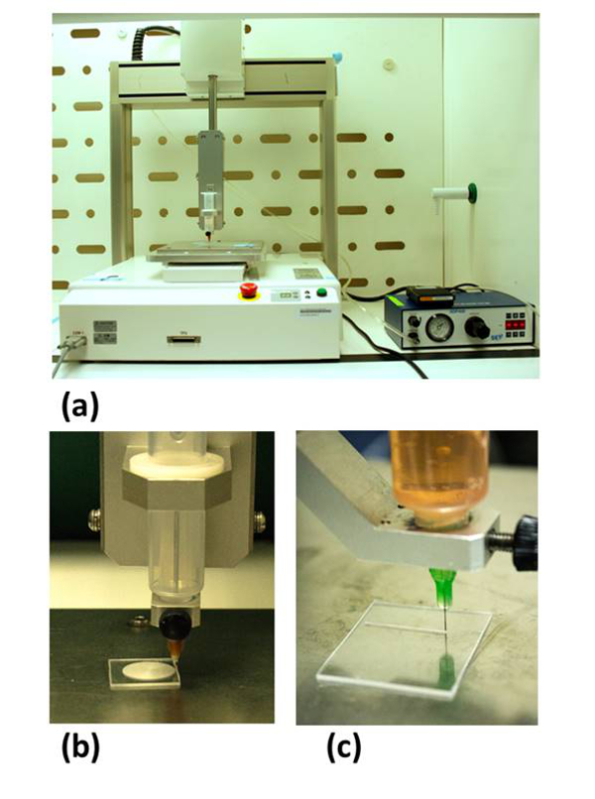 Figure 1:The automated robotic dispensing system. (A) The apparatus was customized with the inclusion of a sharpened stylus (secured in a syringe) central to the print head that etches concentric rings onto a polystyrene slide (B). The print head could then be converted to extrude cell bearing gelatin bioink, with back pressure assisted extrusion, and deposit on the previously etched pattern (C). This figure has been modified from Bhuthalingam et al. 2015 10.
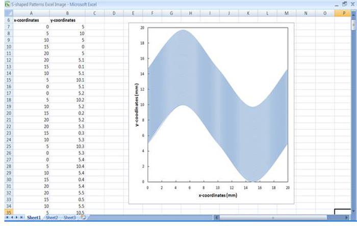 Figure 2:Plotting x-y coordinates in a spreadsheet software. The screen grab shown here demonstrates that the plotted x-y coordinates created a sinusoidal wave pattern as shown by the graph plot. These coordinates were input into the plotting software using the copy/paste function.
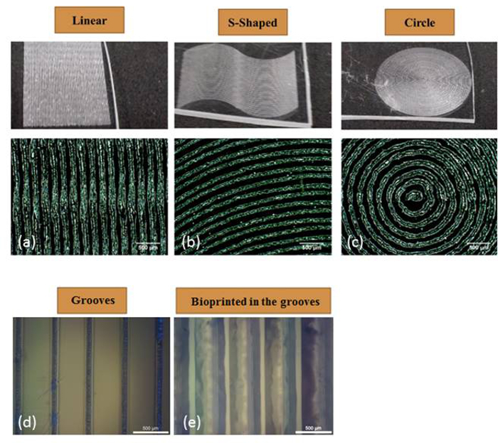 Figure 3: Etched pattern versatility. The coordinates programmed into the plotting software were able to etch linear (A), sinusoidal (B) and concentric circles (C). The grooves etched into polystyrene could be directly printed onto with the hydrogel bioink during the subsequent step (D) and (E). This figure has been modified from Bhuthalingam et al. 2015 10.
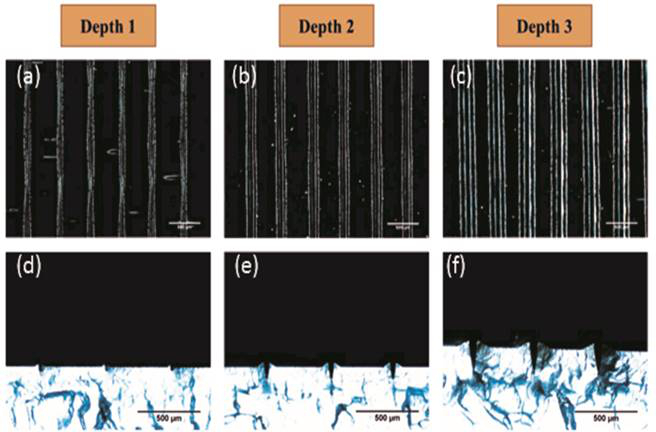 Figure 4:Etched groove depth. The depth of the etched groove can be regulated by the z-axis control of the dispensing system. Images (A) to (C) show the overhead view and (D) to (E) show the cross section. The robot was programmed to etch the surface to a depth of 40 ((A) and (D)), 90 ((B) and (E)) and 180 µm ((C) and (F)). The closeness of the programmed depth and actual etched depth is displayed in Table 1. This figure has been modified from Bhuthalingam et al. 2015 10.
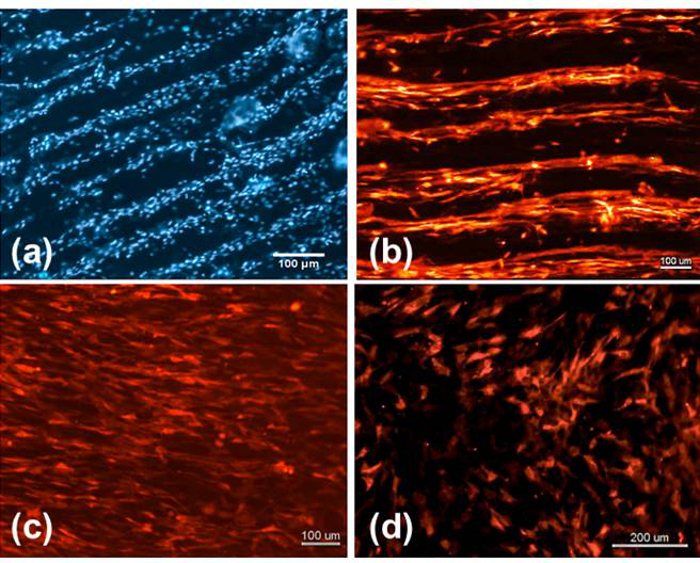 Figure 5: Bioink delivered Mesenchymal stem cells. The RFP-MSCs printed in the bioink onto the etched patterns could sense the features as demonstrated by their elongated morphology and alignment with the grooves (A) and (B) as compared to cells seeded on the features without bioink (i.e., in culture medium) (C) and on a non-patterned surface (D). This figure has been modified from Bhuthalingam et al. 2015 10.
| Programmed depth (µm) | Etched groove depth (µm) |
| 40 | 35 ± 7 |
| 90 | 81 ± 6 |
| 180 | 175 ± 3 |
Table 1: Comparison of programmed versus actual etching depth on polystyrene. This figure has been modified from Bhuthalingam et al. 2015 10.
Discussion
The critical step of this procedure is the actual bioprinting delivery of the stem cells as the process must allow cell sedimentation to the features, print without bioink spreading/bleeding, deliver cells without shear stress cell death and not trigger differentiation towards unwanted lineage.
If the expected cell alignment fails to occur, then the bioink viscosity should be assessed for its suitability for printing. It is important that the bioink allows the cells to sediment to the patterned polymer surface. The concentration of the bioink polymer can be reduced or its temperature increased (up to a maximum of 37 °C), to reduce viscosity and promote cell sedimentation. However, these reductions may cause the bioink to spread/bleed post printing. Here we suggest using 2% gelatin (w/v) dissolved in 1x PBS. If the cell concentration post-printing appears reduced, then the shear stress induced by printing may have compromised the viability of the printed cells7. Check the cells in the bioink before and after printing using a viability assay such as the activation of resazurin fluoresence7. Additionally, if bioprinted stem cells contact the surface but do not align, then it is possible the shear stress during printing decreased their multipotency by triggering an undesired differentiation pathway. Post printing stemness can be assessed by Fluorescence-activated cell sorting (FACS) analysis using stem cell markers such as CD 2910,19,20. If it is found that the shear stress is having deleterious effects on the cells, then the bioink printing viscosity can be reduced by adding or replacing the bioink polymer with a shear thinning one, such as alginate, Pluronic F127, hyaluronic acid, gellan gum, gelatin methacrylate or polyethylene oxide19, 21-25.
Finally, other aspects that can be optimized include the print backpressure, bioink cell density, and nozzle diameter. The backpressure requires optimization to the viscosity of the bioink and can be altered to obtain a discrete unbroken trace. A high cell concentration may increase the bioink viscosity and clog the print head. However, this extrusion process does allow for printing of relatively higher cell densities than other bioprinting methods26,27. The selection of the print nozzle gauge should be considered since small diameter nozzles may produce a finer trace but will be prone to clogging. Tapered nozzles have been found to function better since the same flow rate can be achieved as a cylindrical nozzle but at a lower shear stress hence improved cell viability28.
The backpressure assisted deposition method, also referred to as extrusion bioprinting, has less resolution than other cell printing approaches such as ink jet and laser assisted methodology due to the minimum programmable step length and the spreading of the emerging bioink. However, the backpressure extrusion equipment is most readily modified for the inclusion of an etching stylus. Other methods of producing grooves such as micro-patterning using photolithography followed by PDMS molding have significantly more steps than the robotic etching and the method is less versatile at modifying existing patterns or producing new ones12,15,29-31.
This method offers a tool for in vitro study of cell interactions where the position, orientation, and arrangement of one or more cell types are important. Several cell types including mesenchymal stem cells, fibroblasts, and smooth muscle cells are known to align on surface grooves1,10,14,18. The etched patterns, presented here, can be modified and reprinted very quickly and with ease. This is of interest as surface patterning with grooves has been used in the study of cell adhesion, morphology, migration and stem cell differentiation. Furthermore, it has also been applied to neural and musculoskeletal tissue engineering18, 32,33. Since the grooves do play a role in cell differentiation or phenotype regulation for several cell types, this method can be used to create grooves, to aid differentiation and to deposit cells in discrete rows so that screens can be performed. Currently, we are assessing this method to promote anisotropic cell arrangement of cells for the production of cardiomyocyte cell sheets, as the cellular orientation is important for the function of cardiac tissue12-14,34.
The approach demonstrated here employs a soluble bioink that will eventually dissipate. However, if a more permanent hydrogel coverage is required, then the inclusion of microbial transglutaminase can cross-link and stabilize protein hydrogels such as gelatin based ones without adverse effects on the cells9, 35. Bioinks can also utilize methacrylated polymers for UV initiated crosslinking of cell bearing hydrogels in cytocompatible manner36. However, in our experience, it was found that the transglutaminase crosslinking conferred for an improved interaction between the hydrogel and polymer surface (less readily delaminated), and a more cytocompatible environment when compared to poly(ethylene glycol) diacrylate (PEGDA) hydrogel 37.
Disclosures
The authors declare they have no competing financial interest.
Acknowledgments
The work presented here is supported by the Singapore National Research Foundation under CREATE program (NRF-Technion): The Regenerative Medicine Initiative in Cardiac Restoration Therapy Research Program and by the Public Sector Funding (PSF) 2012 from the Science and Engineering Research Council (SERC) under the Agency for Science, Technology and Research (A*STAR).
References
- Ma Z, et al. In: Cell and Organ Printing. Ringeisen RB, Spargo JB, Wu KP, editors. Netherlands: Springer; 2010. pp. 137–159. [Google Scholar]
- Kaji H, Camci-Unal G, Langer R, Khademhosseini A. Engineering systems for the generation of patterned co-cultures for controlling cell-cell interactions. Biochim Biophys Acta. 2011;1810(3):239–250. doi: 10.1016/j.bbagen.2010.07.002. [DOI] [PMC free article] [PubMed] [Google Scholar]
- Goubko CA, Cao X. Patterning multiple cell types in co-cultures: A review. Materials Science and Engineering: C. 2009;29(6):1855–1868. [Google Scholar]
- Pati F, Jang J, Lee JW, Cho DW. In: Essentials of 3D Biofabrication and Translation. Yoo JJ, editor. Academic Press; 2015. pp. 123–152. [Google Scholar]
- Derby B. Printing and prototyping of tissues and scaffolds. Science. 2012;338(6109):921–926. doi: 10.1126/science.1226340. [DOI] [PubMed] [Google Scholar]
- Malda J, et al. 25th anniversary article: Engineering hydrogels for biofabrication. Adv Mater. 2013;25(36):5011–5028. doi: 10.1002/adma.201302042. [DOI] [PubMed] [Google Scholar]
- Billiet T, Vandenhaute M, Schelfhout J, Van Vlierberghe S, Dubruel P. A review of trends and limitations in hydrogel-rapid prototyping for tissue engineering. Biomaterials. 2012;33(26):6020–6041. doi: 10.1016/j.biomaterials.2012.04.050. [DOI] [PubMed] [Google Scholar]
- Skardal A. In: Essentials of 3D Biofabrication and Translation. Yoo JJ, editor. Academic Press; 2015. pp. 1–17. [Google Scholar]
- Irvine SA, et al. Printing cell-laden gelatin constructs by free-form fabrication and enzymatic protein crosslinking. Biomed Microdevices. 2015;17(1):16. doi: 10.1007/s10544-014-9915-8. [DOI] [PMC free article] [PubMed] [Google Scholar]
- Bhuthalingam R, et al. A novel 3D printing method for cell alignment and differentiation. International Journal of Bioprinting. 2015;1:57–65. [Google Scholar]
- Curtis A, Wilkinson C. Topographical control of cells. Biomaterials. 1997;18(24):1573–1583. doi: 10.1016/s0142-9612(97)00144-0. [DOI] [PubMed] [Google Scholar]
- Tay CY, et al. Micropatterned matrix directs differentiation of human mesenchymal stem cells towards myocardial lineage. Exp Cell Res. 2010;316(7):1159–1168. doi: 10.1016/j.yexcr.2010.02.010. [DOI] [PubMed] [Google Scholar]
- Tay CY, et al. Bio-inspired micropatterned platform to steer stem cell differentiation. Small. 2011;7(10):1416–1421. doi: 10.1002/smll.201002298. [DOI] [PubMed] [Google Scholar]
- Li H, et al. Direct laser machining-induced topographic pattern promotes up-regulation of myogenic markers in human mesenchymal stem cells. Acta Biomater. 2012;8(2):531–539. doi: 10.1016/j.actbio.2011.09.029. [DOI] [PubMed] [Google Scholar]
- Kolind K, Leong KW, Besenbacher F, Foss M. Guidance of stem cell fate on 2D patterned surfaces. Biomaterials. 2012;33(28):6626–6633. doi: 10.1016/j.biomaterials.2012.05.070. [DOI] [PubMed] [Google Scholar]
- Agrawal A, et al. Smooth Muscle Cell Alignment and Phenotype Control by Melt Spun Polycaprolactone Fibers for Seeding of Tissue Engineered Blood Vessels. International Journal of Biomaterials. 2015;2015 doi: 10.1155/2015/434876. [DOI] [PMC free article] [PubMed] [Google Scholar]
- Chang S, et al. Phenotypic modulation of primary vascular smooth muscle cells by short-term culture on micropatterned substrate. PLoS One. 2014;9(2):e88089. doi: 10.1371/journal.pone.0088089. [DOI] [PMC free article] [PubMed] [Google Scholar]
- Li Y, et al. Engineering cell alignment in vitro. Biotechnol Adv. 2014;32(2):347–365. doi: 10.1016/j.biotechadv.2013.11.007. [DOI] [PubMed] [Google Scholar]
- Blaeser A, et al. Controlling Shear Stress in 3D Bioprinting is a Key Factor to Balance Printing Resolution and Stem Cell Integrity. Adv Healthc Mater. 2016;5(3):326–333. doi: 10.1002/adhm.201500677. [DOI] [PubMed] [Google Scholar]
- Nery AA, et al. Human mesenchymal stem cells: From immunophenotyping by flow cytometry to clinical applications. Cytometry Part A. 2013;83A(1):48–61. doi: 10.1002/cyto.a.22205. [DOI] [PubMed] [Google Scholar]
- Guvendiren M, Lu HD, Burdick JA. Shear-thinning hydrogels for biomedical applications. Soft Matter. 2012;8(2):260–272. [Google Scholar]
- Markstedt K, et al. 3D Bioprinting Human Chondrocytes with Nanocellulose-Alginate Bioink for Cartilage Tissue Engineering Applications. Biomacromolecules. 2015;16(5):1489–1496. doi: 10.1021/acs.biomac.5b00188. [DOI] [PubMed] [Google Scholar]
- Kolesky DB, et al. 3D bioprinting of vascularized, heterogeneous cell-laden tissue constructs. Adv Mater. 2014;26(19):3124–3130. doi: 10.1002/adma.201305506. [DOI] [PubMed] [Google Scholar]
- Merceron TK, Murphy SV. In: Essentials of 3D Biofabrication and Translation. Yoo JJ, editor. Academic Press; 2015. pp. 249–270. [Google Scholar]
- Carrow JK, Kerativitayanan P, Jaiswal MK, Lokhande G, Gaharwar AK. In: Essentials of 3D Biofabrication and Translation. Yoo JJ, editor. Academic Press; 2015. pp. 229–248. [Google Scholar]
- Lee KV, et al. In: Bioprinting in Regenerative Medicine. Turksen K, editor. Springer International Publishing; 2015. pp. 33–66. [Google Scholar]
- Ozbolat IT, Hospodiuk M. Current advances and future perspectives in extrusion-based bioprinting. Biomaterials. 2016;76:321–343. doi: 10.1016/j.biomaterials.2015.10.076. [DOI] [PubMed] [Google Scholar]
- Li M, Tian X, Schreyer DJ, Chen X. Effect of needle geometry on flow rate and cell damage in the dispensing-based biofabrication process. Biotechnol Prog. 2011;27(6):1777–1784. doi: 10.1002/btpr.679. [DOI] [PubMed] [Google Scholar]
- Nikkhah M, Edalat F, Manoucheri S, Khademhosseini A. Engineering microscale topographies to control the cell-substrate interface. Biomaterials. 2012;33(21):5230–5246. doi: 10.1016/j.biomaterials.2012.03.079. [DOI] [PMC free article] [PubMed] [Google Scholar]
- Khademhosseini A, et al. Microfluidic patterning for fabrication of contractile cardiac organoids. Biomed Microdevices. 2007;9(2):149–157. doi: 10.1007/s10544-006-9013-7. [DOI] [PubMed] [Google Scholar]
- Chelli B, et al. Neural cell alignment by patterning gradients of the extracellular matrix protein laminin. Interface Focus. 2014;4(1):20130041. doi: 10.1098/rsfs.2013.0041. [DOI] [PMC free article] [PubMed] [Google Scholar]
- Aubin H, et al. Directed 3D cell alignment and elongation in microengineered hydrogels. Biomaterials. 2010;31(27):6941–6951. doi: 10.1016/j.biomaterials.2010.05.056. [DOI] [PMC free article] [PubMed] [Google Scholar]
- Béduer A, et al. Engineering of adult human neural stem cells differentiation through surface micropatterning. Biomaterials. 2012;33(2):504–514. doi: 10.1016/j.biomaterials.2011.09.073. [DOI] [PubMed] [Google Scholar]
- Bian W, Jackman CP, Bursac N. Controlling the structural and functional anisotropy of engineered cardiac tissues. Biofabrication. 2014;6(2):024109. doi: 10.1088/1758-5082/6/2/024109. [DOI] [PMC free article] [PubMed] [Google Scholar]
- Chen PY, et al. Fabrication of large perfusable macroporous cell-laden hydrogel scaffolds using microbial transglutaminase. Acta Biomater. 2014;10(2):912–920. doi: 10.1016/j.actbio.2013.11.009. [DOI] [PubMed] [Google Scholar]
- Bertassoni LE, et al. Direct-write bioprinting of cell-laden methacrylated gelatin hydrogels. Biofabrication. 2014;6(2):024105. doi: 10.1088/1758-5082/6/2/024105. [DOI] [PMC free article] [PubMed] [Google Scholar]
- Zhao X, et al. 3D patterned substrates for bioartificial blood vessels - The effect of hydrogels on aligned cells on a biomaterial surface. Acta Biomater. 2015;26:159–168. doi: 10.1016/j.actbio.2015.08.024. [DOI] [PubMed] [Google Scholar]


