Abstract
We present a light field digital otoscope designed to measure three-dimensional shape of the tympanic membrane. This paper describes the optical and anatomical considerations we used to develop the prototype, along with the simulation and experimental measurements of vignetting, field curvature, and lateral resolution. Using an experimental evaluation procedure, we have determined depth accuracy and depth precision of our system to be 0.05–0.07 mm and 0.21–0.44 mm, respectively. To demonstrate the application of our light field otoscope, we present the first three-dimensional reconstructions of tympanic membranes in normal and otitis media conditions, acquired from children who participated in a feasibility study at the Children’s Hospital of Pittsburgh of the University of Pittsburgh Medical Center.
OCIS codes: (170.0110) Imaging systems, (170.3880) Medical and biological imaging
1. Introduction
Acute otitis media (AOM), or middle ear infection, is the most common infection for which antimicrobial agents are prescribed for children in the United States [1]. Direct and indirect medical costs amount to over $2.8B/year [2]. Diagnosis is difficult even for experienced clinicians. Under-treatment causes increased patient morbidity, whereas over-prescription can lead to the emergence of bacterial resistance. The procedure for diagnosing AOM involves visualizing the tympanic membrane (TM), commonly called the eardrum, with a pneumatic otoscope or an otoendoscope. Studies using these instruments have shown that bulging and discoloration of the TM are the two most effective diagnostic features that differentiate between a normal eardrum, an eardrum with AOM, and an eardrum with OME (otitis media with effusion, characterized by the presence of fluid in the middle ear and no bacterial infection) [3]. Clinically, the most important decision point is accurately diagnosing AOM, because this results in therapeutic implications, i.e., the prescription of an antimicrobial agent in young children. In practice and in limited literature on the subject, the most common error by clinicians is to inaccurately diagnose OME as AOM [4,5], resulting in over-prescription of antibiotics. OME is generally managed conservatively not treating with an antimicrobial agent unless present for a long period of time, such as 3–4 months.
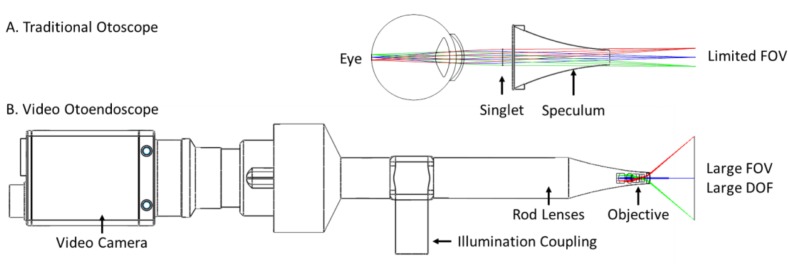
The diagnosis of AOM is not an easy task, because though clinicians can see TM color change from the examination using a traditional optical otoscope, they cannot always distinguish bulging, especially in the youngest children with the smallest canals - and this is the age group in which AOM is most common. A traditional otoscope provides a narrow monocular view of the TM, leading to a limited ability to assess slight differences in shape. These devices use a simple singlet magnifying lens that severely limits the field-of-view (FOV), as shown in Fig. 1(A). On the other hand, new digital otoendoscopes (Fig. 1(B)) can provide high-resolution large FOV images (45–100 degrees) with a large depth-of-field (DOF), but are still limited to two-dimensional (2D) imaging and thus do not provide a three-dimensional (3D) reconstruction of the TM. Lack of 3D information can lead to the misinterpretation of the presence of bulging of the TM, contributing to the most common clinician error: classification of OME as AOM. Diagnostic accuracy of clinicians viewing perfect images captured from digital endoscopes is only about 75% [4,5]. Therefore, precise assessment of the 3D and color properties of the TM are crucial to improve clinicians’ diagnostic accuracy of middle ear pathology.
Fig. 1.
Imaging optics for a traditional otoscope and an otoendoscope.
In our prior work, we presented a single-snapshot 3D video otoscope based on light field technology [6, 7]. This was the first time that a 3D image of a human tympanic membrane was reconstructed from a video otoscope (see supplementary material of [6]). The Light Field Otoscope (LFO) design in [6] was based on a regular camera lens in combination with a light field camera. Here, we present a new optical design for an otoendoscopic LFO that features a small speculum size of 3 mm, has a large FOV, and is designed to precisely measure 3D shape of TM. Moreover, it is a single-snapshot system with short image acquisition time (10–20 ms), which is necessary in order to eliminate motion blur that frequently occurs in imaging the TM of small children.
The main contributions of this paper are the following: 1) we introduce a substantially improved optical design of LFO compared to our prior work, and 2) we present for the first time, 3D color reconstructions of human tympanic membranes from children with different otitis media conditions. The differences between the proposed LFO prototype optical system design and the system presented in [7] are presented in more detail in Sec. 2. It is worth highlighting that the main improvement of the LFO design lies in the decreased size of the speculum tip, going from 5 mm in [6] and 4 mm in [7], to only 3 mm in the design proposed in this paper. This improvement has allowed us to access narrow ear canals and image subjects as young as six months old.
This paper is structured as follows. We first provide background and overview of prior art in digital otoscopy (Sec. 2). The design of the LFO is presented in Sec. 3, followed by the analysis of its optical performance in Sec. 4. Finally, we present in Sec. 5 the clinical results from the LFO imaging study at the Children’s Hospital of Pittsburgh (CHP) of the University of Pittsburgh Medical Center. We conclude with discussion in Sec. 6.
2. Background and prior art
Compared to a traditional camera that records one intensity measurement for each field point, a light field or plenoptic camera records numerous measurements for each field point, corresponding to rays passing through different locations in the aperture. This is achieved by inserting a micro-lens array in front of the imaging sensor [8]. After calibration, plenoptic data can be demultiplexed to a set of multi-view images that form a four-dimensional (4D) data structure called the light field. From the acquired light field, 3D content of the scene can be computed using computer vision algorithms [9]. Likewise, the DOF, focus and perspective can be adjusted through computations after the light field image is acquired [8]. Example applications of light field imaging include re-focusable photography [8], industrial 3D scanning [10] and volumetric microscopy [11].
Light field imaging is well-suited for otoscopy because it can record 3D color image information in a single snapshot with a compact form-factor device. In 2014, we presented our first LFO prototype, which was based on a DSLR-type lens and a plenoptic sensor, configured into an ear imaging device. This otoscope design enabled sub-millimeter 3D estimation of a human ear drum shape ([6], see also supplemental material).
Besides the LFO, there have been other recent research prototypes that record 3D information from the middle ear: an optical coherence tomography (OCT) otoscope [12,13] and a structured illumination otoscope [14]. These methods rely on scanning mechanisms, which could introduce image tearing or motion blur, and make such otoscopes bulky compared to the traditional video ones. The OCT system presented in [13] can achieve fast acquisition rate by using a high-speed line scan camera, but the FOV is limited to 10 degrees, which is significantly below the FOV of commercially available digital otoscopes. FOV of 50 degrees is typically required to image the entire TM and a part of the ear canal. Moreover, the system used in [13] is still very bulky, with the box dimensions of 115 × 115 × 63 mm, on which a metal ear tip and the handle are mounted, so the total system size is even larger. The structured light scanner introduced in 2015 [14], projects a sequence of light patterns on the TM and images the pattern using a web camera. The projection speed is 3 frames per second and a sequence of five patterns is needed for a 3D profile reconstruction of the TM. This amounts to the acquisition time of approximately 1.6 s, which is prohibitively slow for imaging children in clinical settings. The authors do not report the FOV of this system. Finally, the structured illumination otoscope [14] requires a projector to be integrated in the otoscope body, which makes it larger compared to current commercial otoscopes. In comparison to these two prior art approaches, the LFO presented in this article uses a compact image sensor and passive illumination to stream live video with high acquisition time (19 fps with typical exposure time of 10–20 ms), a large FOV of 50 degrees, and the form factor similar to commercial digital otoscopes. The proposed LFO design achieves 3D imaging with depth precision of 0.21 mm in the center of the field and 0.44 mm on the edge of the field. It enables 3D imaging of the TM at video rates. These properties of the LFO make it usable in the clinic on children as young as six months, as verified by our clinical experimental results.
The LFO requires different optical design than traditional otoscopes or otoendoscopes to achieve sub-millimeter depth accuracy. For example, the optics in video otoscopes and otoendoscopes are typically designed to maximize DOF such that the entire image appears in focus; in this case the aperture is small and the object-space numerical aperture (NA) is <0.01 (see Fig. 1(B)). The LFO, on the other hand, requires that images computed from different perspectives (called “multiviews”) have significant parallax, which are then used to estimate depth; thus a larger aperture and object-space NA are required. In practice, mechanical and anatomical constraints limit the aperture size and object-space NA of endoscope-type devices. Previously, we developed two proof-of-concept prototypes with object-space NA of 0.13 [6] and 0.08 [7]. Although these prototypes had excellent depth accuracy, they had smaller FOV, slower frame rate, and larger form-factor than standard otoendoscopes. In an effort to create a more user-friendly LFO, we redesigned the system using a faster camera and smaller optics optimized for a large FOV, 3D imaging of the TM. In comparison to the prototype presented in [7], portability was improved by reducing the optical track length from 180 mm to 112 mm in the current prototype, and by reducing the weight from 458 g to 372 g. More importantly, access to narrow ear canals was enhanced by reducing speculum diameter from 4 mm to 3 mm. The FOV at nominal working distance was expanded from 9.7 to 15.0 mm diameter, allowing the entire eardrum and a part of the ear canal to be visualized in one image. Feedback for navigating the ear canal was improved by increasing frame rate from 12 to 19 frames/second with latency reduced to 150 ms. Optimized illumination components were also integrated into the handle, making the current prototype brighter (from 2mW/cm2 to 50 mW/cm2) and more compact. The following section describes how these specifications were selected based on requirements for pediatric ear imaging.
3. Light field otoscope design
We first describe the hardware design choices for the LFO, including the optical, optomechanical and illumination design.
3.1. Imaging system design
The LFO images the TM, which has a diameter of 7 to 9 mm [15]. During an otoscopic examination, a clinician needs to see not only the TM, but also some of the area surrounding it, in order to guide image acquisition. This constraint requires a larger FOV, typically ranging from 10 to 15 mm in diameter. Depending on age, the curved ear canal is 20 to 30 mm in length, which allows a typical mechanical working distance of 10 to 20 mm from the front of an ear speculum to the TM. This range corresponds to an angular FOV range of 50 to 100 degrees. For comparison, standard otoendoscopes typically have an angular FOV of 60 degrees. The LFO was designed to have a 15 mm diameter FOV at a working distance of 16 mm, corresponding to an angular FOV of 50 degrees. To enable pediatric ear imaging, we designed the distal optics to fit into the tip of a 3 mm pediatric off-the-shelf disposable speculum. The front achromat lens is 2 mm in diameter, which thus allows space for illumination optics. A pupil conjugate is placed near the front lens to maximize object-space NA. Two more achromats of 3 mm and 4 mm diameter are used to form the primary image inside the speculum. A sapphire window is placed distal to the front lens to protect the lens elements. This assembly of optics named “objective lens group” is shown in Fig. 2. The group is approximately image-space telecentric, which images the pupil to infinity.
Fig. 2.
Objective lens group for the LFO.
Next, two “relay lens groups” are configured in a 4F imaging system. The system creates a magnified secondary image in front of a microlens array. Additionally, the first relay lens group re-images the objective lens group pupil to the real aperture plane placed between the relay lenses; the second relay lens group in combination with the microlens array re-images the aperture onto the sensor. The object-space NA is 0.06. The image-space NA of the main lens and the microlens array are matched to be 0.068. Matching the NA of the main lens and the microlens is important in the design of light field cameras to maximize sensor utilization without having overlapping subimages formed behind each micro-lens [8]. The total track length of the optical path is 112 mm. The full system is shown in Fig. 3.
Fig. 3.
Full lens assembly for the LFO.
The microlens array is made up of 50 μm diameter lenslets in a sheet of 10 × 12 mm quartz, arranged in a hexagonal lattice grid pattern. The microlens array is positioned one lenslet focal length from the image sensor; this is known as the Plenoptic 1.0 configuration. Each lenslet captures an image of the pupil with approximately 13 pixel diameter. These pupil images can be used to reconstruct a 13 × 13 matrix of multiview images. Each multiview image in the matrix has a large DOF and corresponds to a different perspective view of the object. The light field image is captured by a 9.2 megapixel 1-inch format charge-coupled device (CCD) sensor. The image is transferred over Universal Serial Bus (USB3), processed, and displayed on a laptop at 19 frames/second.
3.2. Optomechanical and illumination design
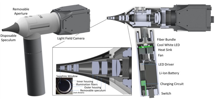
The lens system and illumination components fit inside handheld optomechanics with a total footprint of 160×145×42 mm, which includes the tip and the handle. The objective lenses and first relay lens group are mounted inside a cone-shaped metal lens tube. Glass illumination fibers are epoxied around the tube and then protected with another thin cone-shaped tube with a 3 mm diameter distal tip. The objective assembly mates to a larger one-inch lens tube that contains a removable aperture and the second relay lens group. The design allows access to the aperture to provide flexibility for inserting multi-spectral filters [7]. The entire lens system is covered with a biocompatible plastic shell and a disposable speculum. Another lens tube, which functions as a handle, contains an optical fiber chuck, high-brightness white LED, heat sink, fan, LED driver, Lithium-ion battery, charging circuit, and illumination switch. The prototype has illumination power of approximately 50 mW/cm2. Drawings of the prototype are shown in Fig. 4.
Fig. 4.
LFO optomechanical design. Caution: LFO prototype is an Investigational Device and is limited by Federal Law to investigational use.
4. System characterization
In this section we further describe the system characterization tests for evaluating lateral resolution, depth resolution, and aberrations including vignetting and field curvature.
4.1. Lateral resolution
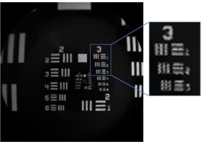
The imaging optics of the LFO are designed to have spot-size smaller than a microlens. The lateral resolution is then limited by the number of lenslets sampling the image, and not by optical aberrations. Although there are super-resolution techniques that can improve resolution of light field images, that is out of scope of this paper and we instead use a one-to-one mapping to reconstruct multiview images in real time, with minimal processing. Thus, the lateral resolution of the LFO is determined by the demagnification of a lenslet onto the object plane. Given a 50 μm lenslet and a total magnification of 0.88, the theoretical lateral sampling is 56.8 μm. Fig. 5 shows an image of a USAF 1951 resolution target. The bars of group 3 element 2 are 55.68 μm wide and can be clearly resolved, despite reconstruction artifacts due to the hexagonal spacing of lenslets.
Fig. 5.
LFO image of a 1951 USAF Resolution Target.
4.2. Depth accuracy and precision
An analysis of depth accuracy and DOF in light field cameras is given in [11]. Briefly, depth accuracy is dependent on the object-space NA, magnification, microlens size, pixel size, and performance of the post-processing algorithm. The object-space NA of the main lens determines the degree of parallax between reconstructed multiview images. Greater parallax provides more disparity between multiview images, which yields a more accurate depth map.
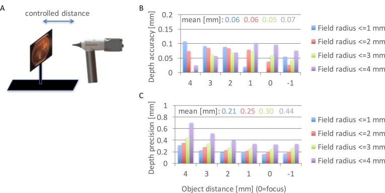
To accurately determine the depth accuracy and precision of the built LFO prototype, we measured it experimentally. We used a flat object with a printed ear drum image (Fig. 6(A)), mounted to a motorized translation stage that moves the object in a controlled way through the axial dimension. For each flat object, we ran our depth estimation algorithm [9] without any post-processing or smoothing, to find depth values for each point on the object. Fig. 6(B) plots the results for different object distances, from 4 mm in front of focus to 1 mm behind focus. In the experimental setting, the focal plane is actually at a certain unknown reference distance. To find that reference distance, we centered one of the object planes to be in focus on-axis, so that the other 5 object planes are exactly 4, 3, 2, 1 and −1 mm away from the reference focus plane. We evaluated depth accuracy and precision as a function of field, i.e., for: field radius <= 1 mm; field radius <= 2 mm; field radius <= 3 mm and field radius <= 4 mm. These field values are with respect to the nominal focal plane. For each of these four fields, we found all depth measurements within that field, for each object depth plane. Depth accuracy is evaluated as an absolute difference of the mean of those measurements and the ground truth plane position value (relative to the reference plane). The results show that the depth accuracy does not change much throughout the focal sweep, with the mean across the four different field configurations staying within 0.05–0.07mm. Depth precision was evaluated as standard deviation of depth for object points within each field and for each object position. We can see that the mean precision stays under 0.3 mm for the field size up to 3 mm off-axis, which is typically the area where most of the TM is imaged (please note that even though the TM is 7–9 mm, the area on the image where the TM lies is smaller due to the tilt of the TM inside the ear canal). The field above 3 mm usually contains the ear canal, in which case the depth accuracy and precision in this area are not so critical. However, even if there is part of the TM outside the 3 mm field, we can still get good depth precision (below 0.4 mm) around the focal plane. Finally, we can notice that there is a systematic loss of depth precision going towards the larger field values. This loss of precision is due to the vignetting present in the system, which is explained in the next section.
Fig. 6.
Depth accuracy estimation. A: Illustration of an experimental setup involving a flat object with TM texture at a controlled distance from the LFO. B: Depth accuracy as a function of field and object distance. C. Depth precision as a function of field and object distance.
4.3. Synthetic aperture and vignetting
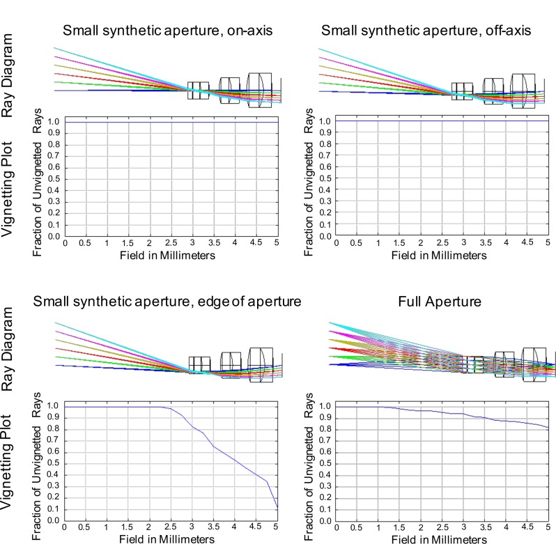
In the LFO, images can be reconstructed from different positions or diameters of the main lens aperture. For example, an image can be reconstructed from the full aperture, which results in the smallest DOF; or an image can be reconstructed from a portion of the aperture, which results in a larger DOF. When designing the main lens, aberrations can be analyzed for each (small aperture) multiview image or for the full aperture. In particular, vignetting for each multiview image has different performance than for the full aperture. Vignetting could affect all multiview images equally, or alternatively, the optical design could tune vignetting to only affect the multiview images corresponding to the outer angle perspectives. In the LFO, ideally the center multiview image is unvignetted, so that there is one large FOV multiview for the clinician; at the same time, the center field points should ideally be unvignetted for all views, which enables better depth accuracy at the image center where the TM is typically imaged. Figure 7 shows vignetting plots for different synthetic aperture positions and sizes. The first and second plots show minimal vignetting for the center-view and off-axis multiview images. The third plot shows significant vignetting for a multiview image reconstructed from the edge of the aperture. The fourth image shows average vignetting for the full aperture, which corresponds to the smallest DOF.
Fig. 7.
Vignetting performance for different synthetic apertures.
4.4. Aberrations and field curvature
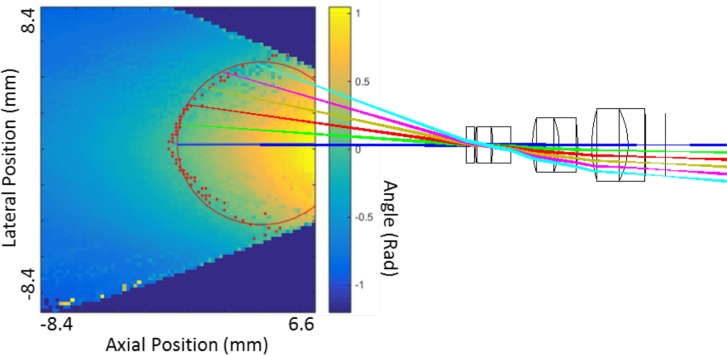
Aberrations in lens systems are typically corrected using added lens elements, aspherical surfaces, and/or specialized optical materials. In contrast, a light field camera uses computational imaging to reconstruct images, so some aberrations such as lateral distortion can be digitally corrected. Field curvature can also be tolerated in the light field camera, because the light field data contains information about the depth of each object point, so curvature of the field in depth can be accounted for when computing 3D reconstructions of an object. Relaxing tolerances of optical aberrations such as field curvature simplifies the lens system, enabling a more compact overall design. The LFO was designed with field curvature of approximately 4.47 mm radius at the nominal focus. The effect of field curvature in a light field camera is that the mapping between the multiview disparity (i.e., parallax) and the absolute depth varies across field points for a flat object. Thus, a calibration procedure is required to evaluate the absolute depth values for all field points, from the disparities estimated using the multiviews [16]. In our calibration procedure, depth values were recorded for an XZ slice throughout the FOV using a point source (250μm fiber optic) scanned across the X and Z axes. Using the algorithm described in [9], the disparity was calculated for all point source measurements. The results are shown in Fig. 8, with values corresponding to zero disparity highlighted with red points. The points fit to a circle of radius 4.52 mm using the method from [17], which closely matches the designed value. The optical design and rays corresponding to the center image are overlaid for comparison.
Fig. 8.
Simulated (red solid line) and measured (red dots) field curvature. LFO objective and rays traced through it are shown for the illustration of the field curvature.
5. Clinical results
The LFO was first tested on adult volunteers with no ear conditions. Figure 9 shows the pipeline of data processing from a light field image obtained at the sensor of the LFO (after demosaicing), where imaging is done on a normal adult TM. The light field image first undergoes multiview extraction using the parameters obtained through calibration. Due to vignetting in the edge of the field, we retain only 7×7 central views out of total 13×13 views. These central views are further fed into the 3D estimation and reconstruction algorithm based on [9]. 3D reconstruction also includes post-processing of the estimated depth map (mean filtering) and mesh surface smoothing based on algebraic point set surfaces [18].
Fig. 9.
The image processing pipeline for 3D reconstruction of the TM. Left: raw light field image from the LFO prototype, with a zoomed area showing the subimages captured behind each microlens. Middle: a matrix of 7×7 multiple views of the TM from different viewpoints, obtained by extracting corresponding pixels from the raw image. Right: 3D surface of the TM obtained after 3D estimation using [9].
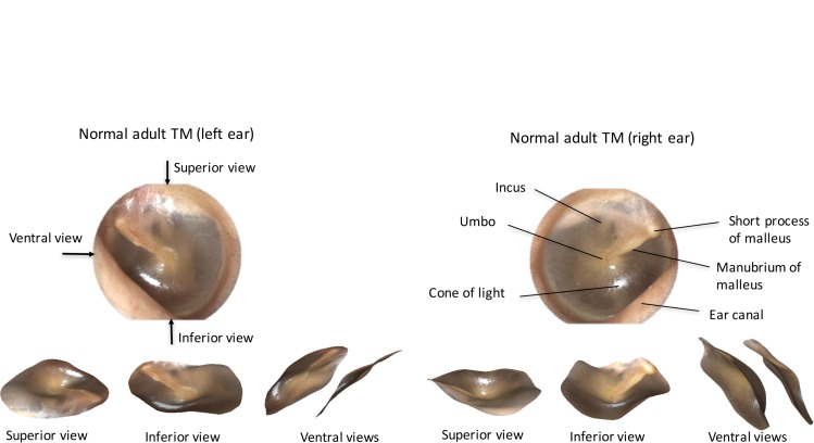
Figure 10 shows 2D previews and 3D reconstructions of a left and right normal adult TM. 3D reconstructions are shown from three viewpoints: the top of the TM (superior view), the bottom of the TM (inferior view) and from the side where the malleus appears (ventral view). Note that these three views are obtained as image snapshots of the 3D ear drum rendering and are not part of the 7×7 views captured by the light field system. We have chosen to display our 3D renderings from these three views, in order to best illustrate the 3D shape through 2D images. The 3D reconstructions shown in Fig. 10 indicate that the TM is slightly cone shaped, consistent with findings in literature [15].
Fig. 10.
LFO images and 3D reconstructions from adult TMs. Left panel top: left ear TM 2D image with arrows showing three different viewpoint directions. Left panel bottom: 3D reconstruction of the left ear TM shown from superior, inferior and ventral views. Right panel top: right ear 2D TM image with index of TM anatomical landmarks. Right panel bottom: 3D reconstruction of the right ear TM shown from superior, inferior and ventral views.
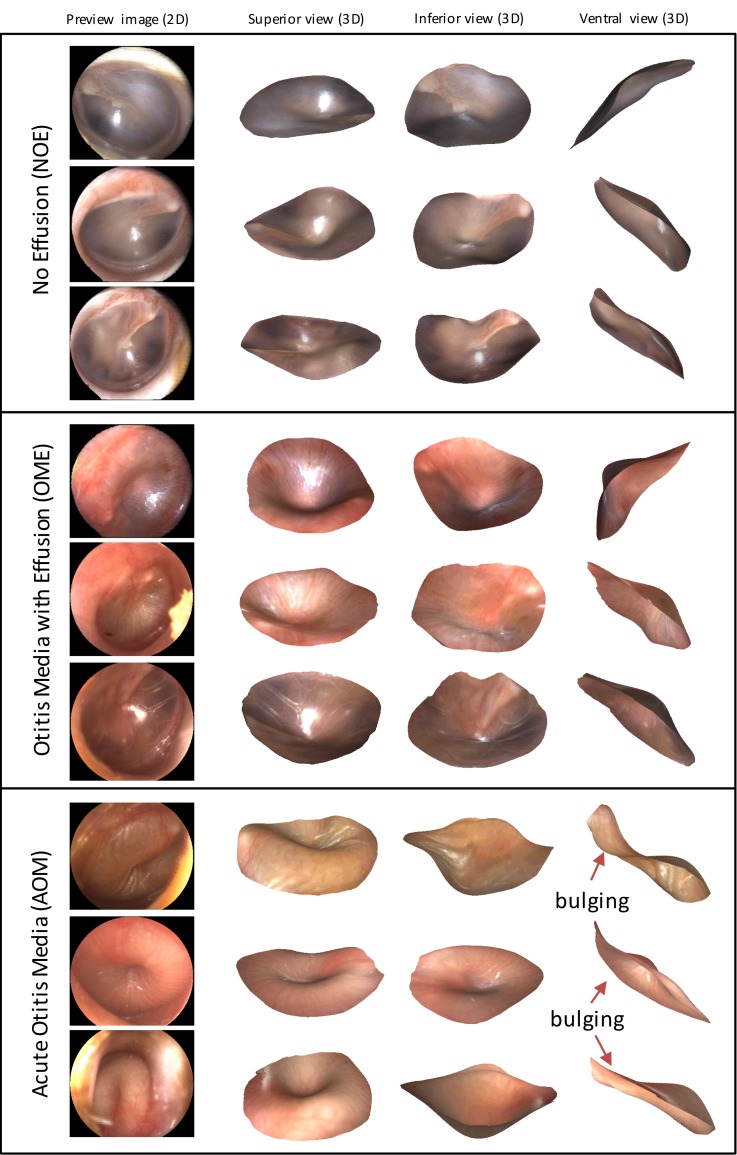
The LFO was further tested on imaging the TMs of children, during a feasibility study at CHP and in accordance with a clinical protocol approved by the Institutional Review Board. Children six months to five years of age were examined by two or more expert otoscopists with a standard manual otoscope. Based on the standard otoscope examination along with other symptoms, clinicians diagnosed participants as having either NOE, OME, or AOM. The TMs of participants were then imaged with the LFO. Figure 11 shows LFO imaging results divided into each diagnostic category. The four columns in Fig. 11 show, respectively, the 2D preview of the TM (central view), as well as superior, inferior and ventral views obtained as image snapshots of the 3D ear drum renderings. Videos of 3D renderings for three examples, one per each diagnostic category, are also included in the supplemental material as Visualization 1 (1.9MB, MOV) , Visualization 2 (2.9MB, MOV) , and Visualization 3 (2.2MB, MOV) . This is the first time in otoscopy that such 3D reconstructions of the TM have been obtained, and interpretation of results still requires a more rigorous analysis to reach further clinical conclusions. However, one can clearly see from the examples shown in Fig. 11 that the TM shape in AOM cases exhibits bulging (convex curvature) and a central concavity, while in the NOE and OME cases it does not. Moreover, one observation that distinguishes OME from NOE is that there is generally more retraction in TMs with OME, which is particularly visible in the OME ventral views in Fig. 11. Finally, consistent with previous findings in otoscopy, the color of the TM is different in NOE cases (pink-gray) and in the OME and AOM cases (more red).
Fig. 11.
2D images and 3D reconstructions obtained in the clinical trials using the LFO prototype. Examples of conditions AOM, OME and NOE from the study participants are displayed (superior, inferior and ventral views).
6. Discussion
We have presented an optical design for the Light Field Otoscope that enables single-snapshot color and 3D imaging of the middle ear. Design choices such as numerical aperture, lateral resolution, depth accuracy/precision and allowance of aberrations (field curvature, vignetting) are discussed and analyzed. Using the proposed optical design, together with the optomechanical and illumination design, we have built a clinic-ready prototype. One limitation of the LFO compared to state of the art digital otoscopes is the reduced lateral resolution, which is due to the acquisition of both spatial and angular samples on a single sensor. Nevertheless, novel super-resolution techniques tailored to light field cameras show great promise for increasing the lateral resolution of LFO.
A major advantage of the LFO compared to existing otoscopes is the capability of capturing 3D color images of the TM surface that may help in quantifying bulging, which is the most important sign for discriminating AOM from OME [3]. The depth accuracy and precision measurements from the prototype show that within the 3 mm FOV radius (6 mm diameter), we get depth values within (0.06+/−0.3) mm of ground truth values. This means that within the range of +/− 2 mm of TM shape change around the neutral position (this is the range we have observed in our data), we get at least six depth levels that we can distinguish. That is enough for the clinical application to otitis media, since in the typical clinical assessment of bulging by TM observation using traditional otoscopes, clinicians judge the appearance as one of the three levels: bulging, neutral or retracted. Furthermore, since our depth precision allows for even finer disambiguation of depth levels, it could even be enough for marking six levels sometimes used in clinical research on otitis media, which are bulging +3 (severe), bulging +2 (moderate), bulging +1 (mild), neutral, mildly retracted and moderately/severely retracted. At the edge of the FOV (above 3 mm), however, our depth precision decays due to vignetting and we can distinguish at least four levels of depth. Nevertheless, this FOV range typically corresponds to where the ear canal is imaged. Even if there is a part of the TM in this outer field, we can still distinguish whether the TM is retracted, neutral or bulging, using the 4 levels of depth in the worst case (far from the focal plane). Therefore, the best case for depth estimation is when the TM is centered within the image. The need for centering of the TM within the image is one limitation of our proposed optical design, which results from the increased vignetting towards the edge of FOV. Another point worth mentioning in the discussion, is that our 3D estimation software uses some post-processing (see Sec. 5), which is necessary to remove noise always present when reconstructing or acquiring a 3D point cloud. This post-processing includes smoothing of the ear-drum surface, which might remove some fine depth variations (for example the edge of the malleus handle), especially if those fall under the reported depth precision levels. However, we can see that this post-processing does not affect the final disambiguation between bulging and other 3D TM shapes, as seen in Fig. 11.
With the proposed LFO, we have acquired first clinical 3D images of human ear drums representing the three diagnostic categories of otitis media (AOM, OME and NOE). The LFO and its accompanying 3D reconstruction software represent a new and promising approach to quantitative measurement of 3D properties of the TM. Since bulging of the TM is the most specific sign of AOM, measuring bulging with LFO has high potential for increasing diagnostic accuracy. Moreover, LFO is a universal 3D ear imaging tool that can be used for imaging other ear conditions that necessitate 3D measurement of the middle ear.
Supplementary Material
Acknowledgments
The authors would like to thank Dr. Kathrin Berkner for her advice and help with project management in its early stage.
Caution: LFO prototype is an Investigational Device and is limited by Federal Law to investigational use.
Funding
The work presented in this manuscript has been funded by Ricoh Innovations, Corp. located in Cupertino, California, United States.
References and links
- 1.American Academy of Pediatrics Subcommittee on Management of Acute Otitis Media , “Diagnosis and management of acute otitis media,” Pediatr. 113(5), 1451 (2004). 10.1542/peds.113.5.1451 [DOI] [PubMed] [Google Scholar]
- 2.Ahmed S., Shapiro N. L., Bhattacharyya N., “Incremental health care utilization and costs for acute otitis media in children,” Laryngoscope 124(1), 301–305 (2014). 10.1002/lary.24190 [DOI] [PubMed] [Google Scholar]
- 3.Shaikh N., Hoberman A., Rockette H. E., Kurs-Lasky M., “Development of an Algorithm for the Diagnosis of Otitis Media,” Acad. Pediatr. 12(3), 214–218 (2012). 10.1016/j.acap.2012.01.007 [DOI] [PubMed] [Google Scholar]
- 4.Kuruvilla A., Shaikh N., Hoberman A., Kovačević J., “Automated diagnosis of otitis media: vocabulary and grammar,” Int. J. Biomed. Imaging 2013, 27 (2013). 10.1155/2013/327515 [DOI] [PMC free article] [PubMed] [Google Scholar]
- 5.Pichichero M. E., Poole M. D., “Assessing diagnostic accuracy and tympanocentesis skills in the management of otitis media,” Arch. Pediatr. Adolesc. Med. 155(10), 1137–1142 (2001). 10.1001/archpedi.155.10.1137 [DOI] [PubMed] [Google Scholar]
- 6.Bedard N., Tošić I., Meng L., Berkner K., “Light field otoscope,” in Imaging and Applied Optics 2014, OSA Technical Digest (Optical Society of America, 2014), paper IM3C.6. [Google Scholar]
- 7.Bedard N., Tošić I., Meng L., Hoberman A., Kovačević J., Berkner K., “In Vivo Middle Ear Imaging with a Light Field Otoscope,” in Optics in the Life Sciences, OSA Technical Digest (Optical Society of America, 2015), paper BW3A.3. [Google Scholar]
- 8.Ng R., Levoy M., Brédif M., Duval G., Horowitz M., Hanrahan P., “Light field photography with a hand-held plenoptic camera,” Computer Science Technical Report CSTR 2(11), 1–11 (2005). [Google Scholar]
- 9.Tošić I., Berkner K., “Light field scale-depth space transform for dense depth estimation,” in Proceedings of the IEEE Conference on Computer Vision and Pattern Recognition Workshops (IEEE, 2014), pp. 435–442. [Google Scholar]
- 10.Perwass C., Wietzke L., “Single lens 3D-camera with extended depth-of-field,” Proc. SPIE 8291, 829108 (2012). 10.1117/12.909882 [DOI] [Google Scholar]
- 11.Levoy M., Ng R., Adams A., Footer M., Horowitz M., “Light field microscopy,” ACM Trans. Graph. 25(3), 924–934 (2006). 10.1145/1141911.1141976 [DOI] [Google Scholar]
- 12.Nguyen C. T., Tu H., Chaney E. J., Stewart C. N., Boppart S. A., “Non-invasive optical interferometry for the assessment of biofilm growth in the middle ear,” Biomed. Opt. Express 1(4), 1104–1116 (2010). 10.1364/BOE.1.001104 [DOI] [PMC free article] [PubMed] [Google Scholar]
- 13.Nguyen C. T., Jung W., Kim J., Chaney E. J., Novak M., Stewart C. N., Boppart S. A., “Noninvasive in vivo optical detection of biofilm in the human middle ear,” Proc. Natl. Acad. Sci. USA 109(24), 9529–9534 (2012). 10.1073/pnas.1201592109 [DOI] [PMC free article] [PubMed] [Google Scholar]
- 14.Das A. J., Estrada J. C., Ge Z., Dolcetti S., Chen D., Raskar R., “A compact structured light based otoscope for three dimensional imaging of the tympanic membrane,” Proc. SPIE 9303, 93031F (2015). 10.1117/12.2079761 [DOI] [Google Scholar]
- 15.Lim D. J., “Structure and function of the tympanic membrane: a review,” Acta Otorhinolaryngol. Belg. 49(2), 101–115 (1994). [PubMed] [Google Scholar]
- 16.Gao L., Bedard N., Tošić I., “Disparity-to-depth calibration in light field imaging,” in Imaging and Applied Optics 2016, OSA Technical Digest (Optical Society of America, 2016), paper CW3D.2. [Google Scholar]
- 17.Gander W., Golub G. H., Strebel R., “Least-squares fitting of circles and ellipses,” BIT Numerical Mathematics 34(4), 558–578 (1994). 10.1007/BF01934268 [DOI] [Google Scholar]
- 18.Guennebaud G., Gross M., “Algebraic point set surfaces,” ACM Trans. Graph. 26(3), 23 (2007). 10.1145/1276377.1276406 [DOI] [Google Scholar]
Associated Data
This section collects any data citations, data availability statements, or supplementary materials included in this article.


